HAL Id: hal-01599439
https://hal.archives-ouvertes.fr/hal-01599439
Submitted on 17 Oct 2017
HAL is a multi-disciplinary open access
archive for the deposit and dissemination of
sci-entific research documents, whether they are
pub-lished or not. The documents may come from
teaching and research institutions in France or
abroad, or from public or private research centers.
L’archive ouverte pluridisciplinaire HAL, est
destinée au dépôt et à la diffusion de documents
scientifiques de niveau recherche, publiés ou non,
émanant des établissements d’enseignement et de
recherche français ou étrangers, des laboratoires
publics ou privés.
Generic modeling propositions for configuring, sale,
product and production
L. Zhang, Élise Vareilles, Michel Aldanondo, P. Helo
To cite this version:
L. Zhang, Élise Vareilles, Michel Aldanondo, P. Helo. Generic modeling propositions for configuring,
sale, product and production. 2012 IEEE INTERNATIONAL CONFERENCE ON INDUSTRIAL
ENGINEERING AND ENGINEERING MANAGEMENT (IEEM), Dec 2012, Hong Kong, Unknown
Region. p. 1959-1963. �hal-01599439�
Abstract - Facilitating product customization, configuration has attracted much attention from both academia and industry alike. However, the available studies and the reported systems focus on sales or product configuration while leaving other important issues in developing customized products unaddressed. In this study, we propose a new configuration concept: integrated SAles,
Product and Production configuration (SAP2 configuration)
to accommodate the entire product customization process. In this study, we focus on the underpinning configuration model: the generic bill of functions, materials and operations (GBoFMO) and discuss it in detail.
Keywords - Customization, Configuration, Generic concept, configuration model
I. INTRODUCTION
Many articles have been published to address, e.g., configuration models, configuration reasoning, configuration knowledge representation [1]. Similarly, prototypical configuration systems and commercial configurators have been reported to facilitate the management of high product variety and the quick definition of customer expected products [2]. In this regard, with focus on sales or product configuration, the existing studies are insufficient to accommodate product customization from a holistic view, i.e., the entire product customization process ranging from functional feature determination to product configuration to production. Pointed out by several authors, production configuration is promising for maintaining production of customized products to be as stable as possible, reducing production lead time and improving product quality [3] [4]. Its rationale lies in configuring routings for customized products from existing process elements while exploiting design similarity and the corresponding process similarity.
Complementing the available studies, in this paper, we put forward a new configuration concept: integrated SAles, Product, and Production configuration (SAP2 configuration), in attempting to help companies
achieve successful product customization by facilitating the entire customization process. It addresses not only sales and product configuration but production configuration. In addition, the SAP2 configuration is
expected to dynamically generate bills of materials (BOMs) and bills of operations (BOOs) visualizing the results of product and production configuration, respectively.
Being fundamental to any configuration systems, a configuration models details the essential configuration
data and their relationships, thus contributing to database and knowledge base construction and all other configuration activities [5]. Therefore, in the light of its important role, in this study, we focus on the conceptual model underpinning the SAP2 configuration, termed as
generic bill of functions, materials, and operations (GBoFMO). In the following sections, we present an overview of the SAP2 configuration, then we concentrate
on the conceptualization of the configuration model. II. OVERVIEW OF SAP2 CONFIGURATION
The SAP2 configuration is proposed to
complement the existing solutions by addressing important, yet insufficiently considered issues: production configuration and generation of BOMs and BOOs. To achieve this, it necessitates a wide range of data and knowledge about sales, marketing, design, planning, process, production, manufacturing resources, costing, etc. Such data and knowledge collaboratively support the SAP2 configuration. The knowledge assists in assessing
customer input requirements and evaluating the selected configuration elements (e.g., functional features, components, operations). For given customer requirements, the SAP2 configuration outputs the sales
configuration. It also outputs the product’s technical design, BOM, routing, and BOO.
A. Process flow of SAP2 configuration
Customers’ answering online questions is the starting point of the SAP2 configuration, and triggers the
subsequent activities. The system will then assess customer inputs by checking their validity. Also assessed is the feasibility of producing the expected features by considering the company’s design and manufacturing capabilities. In case the negative evaluation results, the system informs the customer, and asks she (or he) to consider modifying answers. If the evaluation is positive, the system generates the preliminary sales configuration.
With the preliminary sales configuration, the SAP2
configuration first configures the customized products and the corresponding routings. Subsequently, the configured alternatives are evaluated in terms of production cost and completion time. The evaluation results include a list of configured product alternatives and routings. Also included are the computed production cost and completion time for each pair of product and routing. Based on such results, a company can determine the
2Toulouse University - Mines Albi, Albi, France 3Logistics Research Group, University of Vaasa, Vaasa, Finland
optimal product and routing configuration by making trade-off between cost and lead time and by considering other factors, such as its strategic objectives. With the final decision on product and production configuration, the system calculates the price and delivery lead time for preparing quotations. While we summarize above the major steps involved in SAP2 configuration, we elaborate the modules essential to the SAP2 configuration and the
corresponding functions as follows.
B Essential modules in SAP2 configuration
In the SAP2 configuration, several modules are
necessary, including the user interface, input evaluation, sales/product/production configuration, configuration evaluation, quotation preparation, and order/BOM/BOO generation modules. These modules perform certain functions, and interact with one another towards the delivery of the expected outputs.
User interface module: Like the available studies, the
SAP2 configuration begins with the communication of
customer requirements through the user interface module. This communication can be carried out by, e.g., the customer answering the online questions using his (or her) web browser. By considering the fact that most customers do not have sufficient knowledge about the terminologies describing a product’s functions and technical specifications [6], the questions should be designed using terms that customers are familiar with. In addition to capturing customer requirements, the SAP2 configuration
presents the description of a configured product, the product’s visualization, price and delivery date through the user interface module.
Input evaluation module: The input evaluation
module evaluates customer inputs from several aspects, such as data validity and completeness, customer historic information, product manufacturability, etc. For instance, if the module detects that the input data are incomplete or invalid, it will prompt the user to make necessary changes.
Sales/product/production configuration module: Built
on top of the configuration model – GBoFMO (to be detailed in Section 3), three submodules, namely the sales, product and production configuration submodules, form the configuration module. The sales configuration submodule configures compatible functional features that can meet the evaluated customer requirements. Based on the sales configuration, the product configuration submodule determines technical specifications of the customized product. It first selects appropriate component types, subsequently determines component attributes and their values, and finally decides the design parameters and the corresponding values to define components. The result of product configuration includes several product alternatives. For each alternative, the production configuration submodule configures the routings.
Configuration evaluation module: In addition to
handling configuration, the SAP2 configuration is
expected to deal with evaluation of configured alternatives. The configuration evaluation module performs the evaluation function. It takes the result of the configuration module – pairs of configured product and routing alternatives – as input, and evaluates each pair with respect to production cost and completion time.
Quotation preparation module: Because the accuracy
of quotation with respect to price and delivery lead time is very important in gaining customers [7], in the SAP2
configuration, the quotation is prepared based on the products and routings after configuration evaluation, instead of on the features after sales configuration (as in most of the existing configuration systems). The quotation preparation module calculates the prices and delivery dates based on production costs and completion times resulting from configuration evaluation.
Order/BOM/BOO generation module: Recognizing
the importance of error-free BOMs and BOOs for smooth production, high product quality and reduced production lead time, the SAP2 configuration is proposed to
automatically generate both BOMs and BOOs for configured products and routings. The order/BOM/BOO generation module performs this function, and generates customer orders, BOMs, and BOOs.
III. GBoFMO CONCEPTUALIZATION The GBoFMO is proposed as the underpinning configuration model, organizing sales, design, planning, and process data and knowledge pertaining to a family of customized products. Consistent with the domain concept in product development, the GBoFMO encompasses data from three domains: the functional, design, and process domains. In practice, the functional, design, and process data describe products from three views: the sales, design, and production views. Hence, the GBoFMO consists of these three views along with the mapping between different views.
A. Domains involved in GBoFMO
The domain model helps organize elements in the SAP2 configuration by associating characteristics of
domain data to these configuration elements. For instance, the process domain interprets operations and manufacturing resources necessary to produce output items based on given input items. The interlocking relationships between domains are indicated by arrows. The inter-domain connections together with these in each individual domain are the basis for mapping between two views.
Embodying customer perceptions on product offerings available in a family, the functional domain captures a set of functional features and their values. These features collectively indicate what the products can do and how they look like. A feature can be an atomic one or a composite one. Atomic features individually define product functions or appearance without interacting with
Proceedings of the 2012 IEEE IEEM
other features. For instance, color is an atomic feature describing a bicycle. Composite features describe system functions or appearance at a higher level, and can be decomposed into child features. For instance, as a parent feature, computer memory has two child features: temporary memory and permanent memory. A child feature can be further decomposed into its child features. Such decomposition ends with all features being atomic ones, resulting in a hierarchical structure. The combination of values of child features leads to a value instance of the parent feature (i.e., a specific feature).
Features in the functional domain are delivered by elements in the design domain. The design domain represents products’ technical specifications, more specifically components, their attributes and design parameters. A component can be either an assembly or a part. To deliver variants of the same features (i.e., specific features characterizing the customized products), there are component variants of the same types, forming component families. In accordance with the hierarchical structure of features in the functional domain, assemblies are formed by immediate child assemblies and/or parts. These immediate child assemblies have their child assemblies and/or child parts.
As with features describing customized products, attributes together with their values characterize specific components. These component variants are in turn technically defined by design parameters and the corresponding values. An attribute shows a certain property of a component, indicating component uniqueness. It can be the derived result of a combination of multiple design parameters; it can also be a design parameter (depending on the design parameter). For examples, as an attribute of a steel block, weight is determined by a number of design parameters: length, width, and thickness; the attribute: color is a design parameter at the same time.
Components defined in the design domain are produced using elements in the process domain. These elements include operations, resources, and cycle times. To produce component variants, an operation type has various operations variants, each of which differs from one another in detailed process parameters. In addition, different machines together with other manufacturing resources can perform the same operations while incurring different cycle times, costs, and operations precedence. The operations and manufacturing resources along with operations precedence for producing a customized products form a routing.
B Views and their mapping
In practice, from the sales view, sales people see a product as a set of functional features; from the design view, designers see the product as a list of components; and from the production view, production personnel see the product as a list of ordered operations together with manufacturing resources. Since a GBoFMO organizes
data and knowledge both within and between the respective domains, it enables the integration of several business functions, such as sales, design, and production, in a context coherent framework for configuring product families. It accomplishes this by establishing mapping relationships between the three views of a product family. Mapping relationships exist between any two views of the GBoFMO. First, different customer requirements are identified by a number of functional features in the sales view. Essentially, this identification entails the sales configuration activities. Functional features are mapped from the sales view to component attributes in the design view. In accordance with these component attributes, the technical specifications of components (i.e., design parameters and their interconnections) are further mapped. This mapping from features to component attributes and finally to technical specifications embodies product configuration activities. The mapping between the design and production views reflects the considerations of manufacturing and logistics such that routings are configured to produce customized products by assessing available manufacturing capabilities, production cost, and lead time. The mapping between the production and sales views captures the correspondence between a physical product structure and its functionality, thus providing the necessary information about cost and lead time to facilitate quotation preparation.
C Concept implications and resulting model
The GBoFMO entails a conceptual structure and overall logical organization of a product family from the sales, design, and production views. It acts as a generic umbrella, under which each new sales, product and production configurations can be determined to fulfil individual customer requirements. In this regard, the GBoFMO involves two aspects: 1) a unified common structure within which variations in functions, technical design, and routings for customized products can be differentiated, and 2) the configuration of specific functional features, components, and operations from the unified common structure.
Fig. 1 shows a representation example of the unified GBoFMO structure. Each node in the structure, be it product-related or process related, is a generic concept in the sense that it represents a family of item variants of a same type. In line with the earlier discussion, a product family is characterized by a set of features. There are many interconnections, shown as mapping relationships in the figure, among features, feature values, as well as features and feature values. These mapping relationships can be require meaning the selection of one feature (or a feature value) requires the selection of another, exclude indicating the selection of one feature (or a feature value) excludes the selection of another, and or denoting either one feature (or a feature value) among a number of alternatives can be selected. By satisfying these mapping relationships, the appropriate features and the
corresponding values can be determined, resulting in the sales configuration of a customized product.
Fig. 1. GBoFMO representation
The child component families of a product family have multiple descriptive attributes, each of which can assume a number of values. Mapping relationships exist between features of a product family and child components. Fig. 1 shows such mapping relationships between End Product Family and Assembly Family 1. As a result of these mapping relationships, the determination of component inclusion and component attribute values is based on features. While specific components are described by attribute values, they are technically defined by design parameter values. Thus, there are mapping relationships between component attributes and design parameters, as shown in the figure. In addition, mapping relationships exist among design parameters, parameter values, as well as parameters and values. Fig. 1 gives some examples of these mapping relationships. This is consistent with the fact that design of parent components influences that of child components and that design of sibling components influences design of other sibling components. As with the combination of specific features leading to a customized product, a set of compatible design parameters and the respective value defines a component variant.
To produce parent components, operations, be they assembly operations or manufacturing ones, along with their precedence relationships form subroutings. Connecting all these subroutings by following the parent-child relationships among components leads to a routing to produce a customized product. Similarly, mapping relationships exist between operations and components’ design parameters, as shown in the figure. They determine
specific operations, manufacturing resources, and operations precedence for given child component variants.
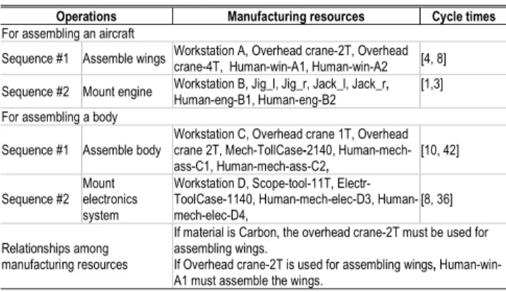
4. INDUSTRIAL EXAMPLE
In this study, we use a family of customized light passenger aircrafts to demonstrate the GBoFMO concept. The major components of a light passenger aircraft include engine, wings, cabin and electronics. Cabin and electronics form the body of an aircraft. For the light passenger aircraft family, its sales view is shown in Table 1. The major features that describe this aircraft family include the number of passengers (NPA), the finishing level (FIN), the speed (SPE) and the flight range (FRA). Each of them can take on a specific value for a customized aircraft. Relationships exist among these features. An example of such relationships is also given in the table. Similarly, the design and production views of the light passenger aircraft family are constructed based on data analysis, as shown in Tables 2 and 3, respectively.
TABLE 1. The sales view of the aircraft family
Features Feature values
FIN : Finishing level Low, Medium, High NPA : Number of passengers 4, 6, 8, 10 SPE : Speed (Km/Hour) 300, 400, 500, 600 FRA : Flight range (Km) 300, 400, 500, 600, 800, 1000
Relationships among features If speed = [400, 600], the flight range 600
TABLE 2. The design view of the aircraft family
Components Attributes and values Design parameters and values
Engine
Gas-need (liter) 400, 600, 800 Tank-size (liter) 400, 800, 1200 Engine-power (hp) 400, …, 1200 Chamber size (liter) 0.4, 0.8, 1.2
# of compressor stages 2, 4, 6 Body Body-weight (kg) [1960 , 4840]
Body-length (m) [8, 16] Body-width (m) [4, 8] Cargo-volume (m3) [0, 2] # of seat supports 2, 3, 4, 5
Wings
Portance [10000 , 50000] Shape Delta, medium Wing-weight (kg) [500, 1000] Wing-length (m) [3, 5]
Material Aluminum, Carbon Cabin Cabin-weight (kg) [1000, 2000]
# of standard seats 4, 6, 8, 10 # of luxury seats 4, 6 Natural light degree Low, high # of portholes 2, 4, 6 Electronics Electric power (kw) [1, 10]
Cabin equipment level Low, medium, high Pilot equipment level Low, medium, high Autonomy (mn) 10, 20, 30 Battery capacity (Amp) 20, 30, 40, 60, 80 Relationships
among attributes and design parameters
If Engine-power is 400, the # of compressor stages is 2 and Chamber size is 0.4. If Engine-power is 500, the # of compressor stages is 4 and Chamber size is 0.8. If Engine-power is 1100, the # of compressor stages is 6 and Chamber size is 1.2. Body-weight = 1000 + 30*body-length*body-width
As shown in Table 2, each of the major component assemblies is described by a number of attributes and technically defined by design parameters. While the configuration of attributes is influenced by the combination of feature values of aircrafts, it determines design parameter values of aircraft components. As End Product Family
•Feature 1 •Child feature 11 • * 113 * 112 * 111,v ,v v •Child feature 12 •v*121, v122* •Feature n Assembly Family 1 •Attribute 1 • , *, 12 * 11av av Attributes: •Attribute 2 • , *, 22 * 21av av •Attribute n • , *, 2 * 1 n nav av •Design parameter 1 • , *, 12 * 11dpv dpv Design parameters: •Design parameter 2 • , *, 22 * 21dpv dpv •Design parameter n •dpv*n1,dpv*n2, Assembly Family 2 •Attribute 1 • , *, 12 * 11av av Attributes: •Attribute 2 • , *, 22 * 21av av •Attribute n • , *, 2 * 1 n nav av •Design parameter 1 • , *, 12 * 11dpv dpv Design parameters: •Design parameter 2 • , *, 22 * 21dpv dpv •Design parameter n • , *, 2 * 1 n ndpv dpv Assembly Family 3 •Attribute 1 • , *, 12 * 11av av Attributes: •Attribute 2 • , *, 22 * 21av av •Attribute n • , *, 2 * 1 n nav av •Design parameter 1 • , *, 12 * 11dpv dpv Design parameters: •Design parameter 2 • , *, 22 * 21dpv dpv •Design parameter n •dpvn*1,dpv*n2, Part Family 21 •Attribute 1 • , *, 12 * 11av av Attributes: •Attribute 2 • , *, 22 * 21av av •Attribute n • , *, 2 * 1 n nav av •Design parameter 1 • , *, 12 * 11dpv dpv Design parameters: •Design parameter 2 • , *, 22 * 21dpv dpv •Design parameter n •dpv*n1,dpv*n2, Part Family 22 •Attribute 1 • , *, 12 * 11av av Attributes: •Attribute 2 • , *, 22 * 21av av •Attribute n • , *, 2 * 1 n nav av •Design parameter 1 • , *, 12 * 11dpv dpv Design parameters: •Design parameter 2 • , *, 22 * 21dpv dpv •Design parameter n •dpv*n1,dpv*n2, Operation 1 Operation 2 Operation 1 Operation 2 Legend: : Operations precedence : Output product : Input material : Mapping relationship
End Product Family •Feature 1 •Child feature 11 • * 113 * 112 * 111,v ,v v •Child feature 12 •v*121, v122* •Feature n Assembly Family 1 •Attribute 1 • , *, 12 * 11av av Attributes: •Attribute 2 • , *, 22 * 21av av •Attribute n • , *, 2 * 1 n nav av •Design parameter 1 • , *, 12 * 11dpv dpv Design parameters: •Design parameter 2 • , *, 22 * 21dpv dpv •Design parameter n •dpv*n1,dpv*n2, Assembly Family 2 •Attribute 1 • , *, 12 * 11av av Attributes: •Attribute 2 • , *, 22 * 21av av •Attribute n • , *, 2 * 1 n nav av •Design parameter 1 • , *, 12 * 11dpv dpv Design parameters: •Design parameter 2 • , *, 22 * 21dpv dpv •Design parameter n • , *, 2 * 1 n ndpv dpv Assembly Family 3 •Attribute 1 • , *, 12 * 11av av Attributes: •Attribute 2 • , *, 22 * 21av av •Attribute n • , *, 2 * 1 n nav av •Design parameter 1 • , *, 12 * 11dpv dpv Design parameters: •Design parameter 2 • , *, 22 * 21dpv dpv •Design parameter n •dpvn*1,dpv*n2, Part Family 21 •Attribute 1 • , *, 12 * 11av av Attributes: •Attribute 2 • , *, 22 * 21av av •Attribute n • , *, 2 * 1 n nav av •Design parameter 1 • , *, 12 * 11dpv dpv Design parameters: •Design parameter 2 • , *, 22 * 21dpv dpv •Design parameter n •dpv*n1,dpv*n2, Part Family 22 •Attribute 1 • , *, 12 * 11av av Attributes: •Attribute 2 • , *, 22 * 21av av •Attribute n • , *, 2 * 1 n nav av •Design parameter 1 • , *, 12 * 11dpv dpv Design parameters: •Design parameter 2 • , *, 22 * 21dpv dpv •Design parameter n •dpv*n1,dpv*n2, Operation 1 Operation 2 Operation 1 Operation 2 Legend: : Operations precedence : Output product : Input material : Mapping relationship
Proceedings of the 2012 IEEE IEEM
shown in Table 3, for assembling an aircraft, two assembly operations, namely assemble wings and mount engine, are necessary. In addition, assemble wings must be carried out before mount engine. The specific manufacturing resources required and the estimated cycle times to be incurred are influenced by the design parameters of input components.
TABLE 3. The production view of the aircraft family
Operations Manufacturing resources Cycle times
For assembling an aircraft
Sequence #1 Assemble wings Workstation A, Overhead crane-2T, Overhead crane-4T, Human-win-A1, Human-win-A2 [4, 8] Sequence #2 Mount engine Workstation B, Jig_l, Jig_r, Jack_l, Jack_r, Human-eng-B1, Human-eng-B2 [1,3] For assembling a body
Sequence #1 Assemble body
Workstation C, Overhead crane 1T, Overhead crane 2T, Mech-TollCase-2140, Human-mech-ass-C1, Human-mech-ass-C2, [10, 42] Sequence #2
Mount electronics system
Workstation D, Scope-tool-11T, Electr-ToolCase-1140, mech-elec-D3, Human-mech-elec-D4, [8, 36] Relationships among
manufacturing resources
If material is Carbon, the overhead crane-2T must be used for assembling wings.
If Overhead crane-2T is used for assembling wings, Human-win-A1 must assemble the wings.
Note: the unit of measure of cycle time is hour
Upon analyzing the sales, design, planning and production data and knowledge pertaining to the aircraft family, the GBoFMO is constructed, as shown in Fig. 2. The GBoFMO represents the sales data (e.g., features of the aircraft family), the design data (e.g., wing attributes and design parameters) and the production data (e.g., the assembly operations to assemble an aircraft) in one unified structure. Thus, it enables a corresponding configuration system to consistently configure the set of features of a customized aircraft, component designing aircrafts and operations producing aircraft.
Fig. 2. The GBoFMO of the aircraft family
5. CONCLUSION
In view of the limitations of the available studies on configuration, in this paper, we proposed the SAP2
configuration to accommodate product customization from a holistic view. Built upon the principle of automating most of the processes associated with specification, engineering, and production of a customized product, the SAP2 configuration enables the
configuration of functional features, physical components and their relationships, operations and manufacturing resources based on individual customer requirements. It is also expected to dynamically generate the technical documents, such as BOMs and BOOs, to contribute to improve production performance by having error-free BOMs and BOOs. As a starting point, we discussed in detail the model underpinning the the SAP2 configuration:
the GBoFMO. In accordance with the functions of the the SAP2 configuration, the GBoFMO involves knowledge
and data within and between the functional, design, and process domains, and embodies a product family from the three associated views: the sales, design, and production views. We also used a family of light passenger aircrafts to demonstrate the GBoFMO. Built on top of this study, in the future, we will address the other issues in the SAP2
configuration, including configuration evaluation, data and knowledge modeling, configuration modeling, system architecture design and prototype development.
REFERENCES
[1] Blecker, T., Abdelkafi, N., Kreuter, G. and Friedrich, G., (2004). Product configuration systems: state-of-the-art, conceptualization and extensions. Proceedings of the 8th
Conference on Software Engineering and Artificial Intelligence, 25-36, Sousse, Tunisia.
[2] Forza, C. and Salvador, F., (2002). Managing for variety in the order acquisition and fulfillment process: the contribution of product configuration systems. International
Journal of Production Economics, 76(1), 87-98.
[3] Aldanondo, M. and Vareilles E., (2008). Configuration for mass customization: how to extend product configuration towards requirements and process configuration. Journal of
Intelligent Manufacturing, 19(5), 521-535.
[4] Zhang, L. and Rodrigues, B., (2010). Nested colored timed Petri nets for production configuration of product families.
International Journal of Production Research, 48(6),
1805-1833.
[5] Zhang, J., Wang, Q., Li, W. and Zhong, Y., (2005). Configuration-oriented product modeling and knowledge management for made-to-order manufacturing enterprises.
International Journal of Advanced Manufacturing Technology, 25, 41-52.
[6] Blecker, T., Abdelkafi, N., Kaluza, B. and Friedrich, G., (2003). Key metrics system for variety steering in mass customization. Proceedings of the 2nd Interdisciplinary
World Congress on Mass Customization and Personalization – MCPC’03, Munich, Germany.
[7] Veeramani, D. and Joshi, P., (1997). Methodologies for rapid and effective response to requests for quotation (RFQs). IIE Transactions, 29, 825-838.
Plane
FIN : finish-level NPA : number passengers SPE : speed FRA : flight Range
Engine
GAS : gas-need POW : engine-power EWE : engine-weight TSZ : tank-size CHA : chamber size NCS : num. comp.stag.
Body
BWE : body-weight CGO : cargo volume BLE : body-length BWI : body-width SSQ : seat sup. quant.
Wings POR : portance WWE : wing-weight SHA : shape WLE : wing-length MAT : material Cabin CWE : cabin-weight NLD : natural light degree NSS : number stand seats NLS : number lux seats NPO : number portholes
Electronics
EPO : electric power AUT : autonomy CEL : cabin equip level PEL : pilot equip level BAC : battery cappacity
Legend: : Operations precedence : Output product : Input material : Mapping relationship • • Body Attributes BWE CGO …. Design param. BLE BWI SSQ …. Wings Attributes POR WWE …. Design param. SHA WLE MAT …. Engine Attributes GAS POW EWE …. Design param. TSZ CHA NCS …. Electronics Attributes EPO AUT …. Design param. CEL PEL BAC …. Cabin Attributes CWE NLD …. Design param. NSS NLS NPO …. Plane Global characteristics. FIN NPA Performance SPE FRA Assemble body Resource Time Mount Electro Resource Time Assemble wings Resource Time Mount engine Resource Time Plane FIN : finish-level NPA : number passengers SPE : speed FRA : flight Range
Engine
GAS : gas-need POW : engine-power EWE : engine-weight TSZ : tank-size CHA : chamber size NCS : num. comp.stag.
Body
BWE : body-weight CGO : cargo volume BLE : body-length BWI : body-width SSQ : seat sup. quant.
Wings POR : portance WWE : wing-weight SHA : shape WLE : wing-length MAT : material Cabin CWE : cabin-weight NLD : natural light degree NSS : number stand seats NLS : number lux seats NPO : number portholes
Electronics
EPO : electric power AUT : autonomy CEL : cabin equip level PEL : pilot equip level BAC : battery cappacity
Legend: : Operations precedence : Output product : Input material : Mapping relationship • • Plane FIN : finish-level NPA : number passengers SPE : speed FRA : flight Range
Engine
GAS : gas-need POW : engine-power EWE : engine-weight TSZ : tank-size CHA : chamber size NCS : num. comp.stag.
Body
BWE : body-weight CGO : cargo volume BLE : body-length BWI : body-width SSQ : seat sup. quant.
Wings POR : portance WWE : wing-weight SHA : shape WLE : wing-length MAT : material Cabin CWE : cabin-weight NLD : natural light degree NSS : number stand seats NLS : number lux seats NPO : number portholes
Electronics
EPO : electric power AUT : autonomy CEL : cabin equip level PEL : pilot equip level BAC : battery cappacity
Legend: : Operations precedence : Output product : Input material : Mapping relationship • • Legend: : Operations precedence : Output product : Input material : Mapping relationship • • Legend: : Operations precedence : Output product : Input material : Mapping relationship • • Body Attributes BWE CGO …. Design param. BLE BWI SSQ …. Wings Attributes POR WWE …. Design param. SHA WLE MAT …. Engine Attributes GAS POW EWE …. Design param. TSZ CHA NCS …. Electronics Attributes EPO AUT …. Design param. CEL PEL BAC …. Cabin Attributes CWE NLD …. Design param. NSS NLS NPO …. Plane Global characteristics. FIN NPA Performance SPE FRA Assemble body Resource Time Mount Electro Resource Time Assemble wings Resource Time Mount engine Resource Time Body Attributes BWE CGO …. Design param. BLE BWI SSQ …. Body Attributes BWE CGO …. Design param. BLE BWI SSQ …. Wings Attributes POR WWE …. Design param. SHA WLE MAT …. Wings Attributes POR WWE …. Design param. SHA WLE MAT …. Engine Attributes GAS POW EWE …. Design param. TSZ CHA NCS …. Engine Attributes GAS POW EWE …. Design param. TSZ CHA NCS …. Electronics Attributes EPO AUT …. Design param. CEL PEL BAC …. Electronics Attributes EPO AUT …. Design param. CEL PEL BAC …. Cabin Attributes CWE NLD …. Design param. NSS NLS NPO …. Cabin Attributes CWE NLD …. Design param. NSS NLS NPO …. Plane Global characteristics. FIN NPA Performance SPE FRA Plane Global characteristics. FIN NPA Performance SPE FRA Assemble body Resource Time Assemble body Resource Time Mount Electro Resource Time Mount Electro Resource Time Assemble wings Resource Time Assemble wings Resource Time Mount engine Resource Time Mount engine Resource Time