Design and implementation of a T impedance matching network for
the radiocommunication subsystem aboard
the OUFTI-1 nanosatellite
Mohamed Boutaayamou, Nicolas Crosset, Xavier Werner, and Jacques G. Verly
Dept. of Electrical Engineering and Computer Science, INTELSIG Laboratory, University of Liège, Belgium Contact: mboutaayamou@ulg.ac.be
Abstract ‒ We describe how we handled an unexpected impedance matching issue on the receiver side (at UHF) of the
radiocommunication system aboard the OUFTI-1 nanosatellite of the University of Liège. Our approach relied on a combination of novel analytical developments combined with experimentation.
This paper deals with an unexpected antenna impedance matching (IM) problem that arose during the construction of the radiocommunication subsystem aboard the OUFTI-1 nanosatellite. This subsystem contains (1) an RF transceiver allowing to transmit (Tx) and to receive (Rx) D-STAR(1) voice and data signals and
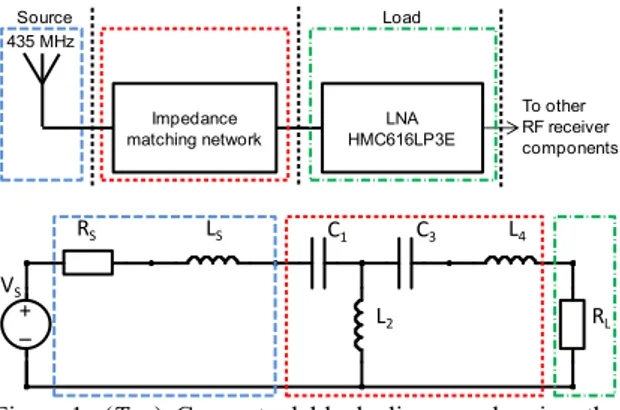
AX.25 telecommand/telemetry signals, and (2) an always-on emergency-beacon transmitter sending OOK signals. Tx is at VHF (145 MHz) and Rx at UHF (435 MHz). The IM issue concerns the match between the Rx antenna (for D-STAR and AX.25 signals) and the subsequent low-noise amplifier (LNA). Here, the source is the antenna and the load is the LNA, and the problem is that of matching the source impedance to the load impedance (see Figure 1(Top)). The goal of the matching is - as usual - to minimize signal reflections and to ensure a maximum transfer of power from the source to the load over a given frequency band of interest. The IM network must also provide proper rejection outside this band.
The problem considered here arose because of a discrepancy between the topology of the matching circuit we had specified (a -network in its high-pass version) and the one that was manufactured for us (a T network). The T network resulted from the erroneous omission of some soldering pads/holes in the printed circuit board. Rather than ordering a new fully populated board, we investigated whether we could meet our strict frequency constraints with the T topology available to us. The present paper describes how we managed to solve the problem. The available T network included two series capacitors, one series inductor, and one shunt inductor, as depicted in Figure 1(Bottom). Given the absence of a second shunt component in this T network, finding the adequate values for the four passive components of the network was not an easy task. We started with a trial and error approach to determine these values; however, this proved to be time-consuming and ineffective.
We then decided to approach the problem analytically. Simplifying somewhat, we first derived the transfer function of the IM network, and we then devised a procedure for finding the best possible (theoretical) values for the four components of the T network. The task proved to be more complicated than expected, but we found inspiration in [1]. However, we had to completely adapt the approach of [1] since we needed a high-pass T matching network, while [1] considered a low-pass T matching network. A major feature of the approach in [1] was to use, as a steppingstone, the loaded quality factor Q. We did the same, but we had to use quite different expressions for Q.
(1) D-STAR is the acronym for Digital Smart Technologies for Amateur
Radio. A homemade D-STAR transceiver is the main payload aboard the OUFTI-1 nanosatellite.
To use our formulas, we needed to know the source (antenna) impedance and the load (LNA) impedance. We found the first experimentally using a vector network analyzer (ZVA24), and the second via the datasheet of the LNA.
From the analytically obtained frequency response of the T network, we selected graphically the adequate value for the loaded quality factor Q. Using this value of Q, we determined analytically the required values for the capacitors and inductors of the T network (i.e., C1, L2, C3,
and L4) using the conjugate matching condition. Since the
theoretically determined values for C1, L2, C3, and L4 did
not - without surprise - correspond to commercially available values, we built several test IM networks and measured their performance experimentally. The goal was to find the combination of commercially-available values that would allow us to meet in the best possible way the required pass-band, while sufficiently attenuating the RF Tx frequency and its harmonics (particularly when the nanosatellite operates in the simultaneous Tx and Rx modes). For this, we performed the measurement of the frequency response and the Smith chart representation for each T network using the vector network analyzer (ZVA24). The experimental results showed that the IM problem could be handled using the available T topology in conjunction with commercially-available C and L components.
Figure 1: (Top) Conceptual block diagram showing the source (i.e., the antenna), the impedance matching network, and the load (i.e., the input impedance of the LNA). (Bottom) Electrical representation of the problem, showing the equivalent components of the source and load, with the topology of the T network between them.
Acknowledgements
We would like to thank P. Beerten and V. Beauvois from our department for their assistance with the experimental measurements.
Reference
[1] B.K. Chung. “Q-based design method for T network impedance matching,” Microelectr. J., 37(9), 1007–11, 2006.
Impedance
matching network HMC616LP3ELNA
To other RF receiver components 435 MHz Source Load + Title Author File Revision Document Date Sheets E:\trav\systeme_3D_pour_l_analyse_de_la_marche\conf\ursibenelux_2014\fig\ress\circuit_tinycad.dsn 1.0 1 of 1 L2 C1 C3 L4 LS RS RL + – VS
