HAL Id: tel-01481318
https://tel.archives-ouvertes.fr/tel-01481318
Submitted on 2 Mar 2017HAL is a multi-disciplinary open access
archive for the deposit and dissemination of sci-entific research documents, whether they are pub-lished or not. The documents may come from teaching and research institutions in France or abroad, or from public or private research centers.
L’archive ouverte pluridisciplinaire HAL, est destinée au dépôt et à la diffusion de documents scientifiques de niveau recherche, publiés ou non, émanant des établissements d’enseignement et de recherche français ou étrangers, des laboratoires publics ou privés.
Electronic transfer within a microbial fuel cell. Better
understanding of Experimental and Structural
Parameters at the Interface between Electro-active
Bacteria and Carbon-based Electrodes
David Pinto
To cite this version:
David Pinto. Electronic transfer within a microbial fuel cell. Better understanding of Experimental and Structural Parameters at the Interface between Electro-active Bacteria and Carbon-based Elec-trodes. Material chemistry. Université Pierre et Marie Curie - Paris VI, 2016. English. �NNT : 2016PA066367�. �tel-01481318�
− 1
Université Pierre et Marie Curie
Ecole doctorale 397 − Physique et Chimie des Matériaux
Laboratoire Chimie de la Matière Condensée de Paris
Matériaux Hybride et Nanomatériaux
T
RANSFERT
E
LECTRONIQUE AU SEIN
D
’
UNE
P
ILE A
C
OMBUSTIBLE
M
ICROBIENNE
Compréhension des Paramètres Expérimentaux et Structuraux à l’Interface
entre une Bactérie électro-active et une Electrode carbonée
Présentée par :
David PINTO
Thèse de doctorat de Chimie des Matériaux
Dirigée par : Pr. Christel Laberty-Robert et Dr. Thibaud Coradin
Présentée et soutenue publiquement le 14 Novembre 2016
Devant le jury composé de :
Dr. Sara Cavaliere . . . Maitre de Conférence HDR à l’Université de
Montpellier, France − ICGM Rapporteur
Dr. Elisabeth Lojou . . . Directrice de Recherche CNRS à l’Unité de
Bioénergétique et Ingénierie des Protéines Rapporteur Pr. Abraham Esteve Núñez . . . Professeur à l’Université of Alcalá, Madrid, Spain –
Bioelectrogenesis Examinateur
Pr. Claude Jolivalt . . . Professeur à l’Université Pierre et Marie Curie,
Paris 6, France − LRS Examinatrice
Dr. Eric Lafontaine . . . Docteur HDR, Responsable de domaine scientifique
à la DGA Examinateur
Dr. Thibaud Coradin . . . Directeur de Recherche CNRS à l’Université Pierre
et Marie Curie, Paris, France − LCMCP Co-directeur de Thèse Pr. Christel Laberty-Robert . . . Professeur à l’Université Pierre et Marie Curie,
−2
− 3
E
LECTRONIC
T
RANSFER
WITHIN A
M
ICROBIAL
F
UEL
C
ELL
Better understanding of Experimental and Structural Parameters at the
Interface between Electro-active Bacteria and Carbon-based Electrodes
Presented by:
David PINTO
Doctoral thesis of Material Chemistry
Supervised by: Pr. Christel Laberty-Robert et Dr. Thibaud Coradin
Thesis presented and defended on 14th November 2016
− 5
« La vie, c’est comme une bicyclette,
il faut avancer pour garder l’équilibre. »
TABLE OFCONTENT− 11
T
ABLE
O
F
C
ONTENTS
TABLE OFCONTENT−12
TABLE OFCONTENT− 13
General Introduction 17
Chapter 1 − Literature Review 21
1.1.
GENERAL ENERGETIC CONTEXT ... 25
1.2.
GENERAL ASSESSMENTS ABOUT BIOFUEL CELLS ... 25
1.2.1. From fuel cell to biofuel cell ... 25
1.2.2. Microbial Fuel Cells and Enzymatic Fuel Cells ... 27
1.2.2.1. Enzymatic Fuel Cell. ... 27
1.2.2.2. Microbial Fuel Cell. ... 28
1.2.3. Microbial Electrochemical Systems ... 29
1.3.
M
ICROBIALF
UELC
ELLS... 31
1.3.1. Principle of MFC electricity generation ... 31
1.3.2. Microbial Electron Transfer ... 32
1.3.2.1. Indirect Electron Transfer. ... 33
1.3.2.2. Mediated Electron Transfer. ... 33
1.3.2.3. Direct Electron Transfer. ... 34
1.3.3. Exoelectrogenic bacterium ... 35
1.3.3.1. Shewanella oneidensis. ... 36
1.3.3.2. Pure culture versus mixed culture. ... 36
1.3.4. Biofilm ... 37
1.4.
MICROBIAL FUEL CELLS EFFICIENCY: KEY FACTORS ... 38
1.4.1. Factors related to the bacterium ... 39
1.4.2. Factors related to the cell architecture ... 40
1.4.3. Factors related to the electronic transfer ... 40
1.5.
MICROBIAL FUEL CELLS MATERIALS & ARCHITECTURE ... 41
1.5.1. Anode materials ... 41
1.5.1.1. Carbon-based materials. ... 41
1.5.1.2. Surface Treatment on Carbon based materials. ... 43
1.5.1.3. Metallic and metal coated materials. ... 46
1.5.2. Cathode materials. ... 47
1.5.3. Separator: proton exchange membrane ... 49
1.5.4. Global cell architectures ... 51
TABLE OFCONTENT−14
Chapter 2 − External Parameters Affecting Bacterium
Adhesion and Microbial Fuel Cell Performanced 59
2.1.
INTRODUCTION AND OBJECTIVES ... 63
2.2.
CARBON FELT AS AN ANODIC CARBON-BASED ELECTRODE ... 64
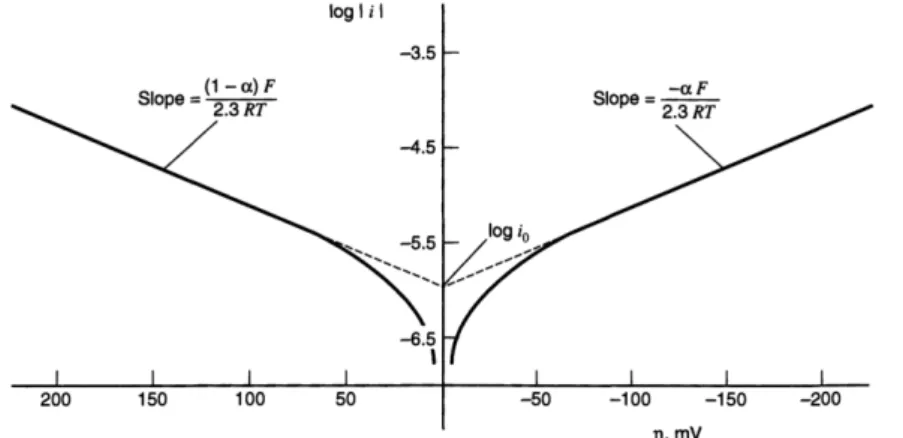
2.2.1. How an electrochemical reaction occurs? ... 64
2.2.1.1. Charge transfer. ... 65
2.2.1.2. Mass transfer. ... 67
2.2.2. Carbon felt as carbon-based electrode for electrochemistry ... 69
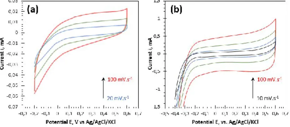
2.2.3. Electrochemical characterization of a carbon felt ... 70
2.2.3.1. Capacitive behavior of a raw carbon felt. ... 71
2.2.3.2. Faradaic behavior of a raw carbon felt. ... 72
2.2.3.3. Hydrophilic treatment effect on the faradaic current. ... 78
2.2.3.4. Dimensional effect and probes concentration effect. ... 81
2.3.
BACTERIA GROWTH CONDITIONS AND ACCLIMATION ... 83
2.3.1. Media and solutions for growth. ... 84
2.3.2. Growth protocol ... 85
2.3.2.1. Preparation of the pre-cultures. ... 85
2.3.2.2. Preparation of the culture and growth curve determination. ... 85
2.3.3. Bacteria counting and OD600/cfu correlation. ... 86
2.3.4. Growth conditions effect on S. oneidensis multiplication. ... 87
2.3.4.1. Lag-phase. ... 88
2.3.4.2. Log-phase. ... 89
2.3.4.3. Stationary-phase. ... 89
2.3.4.4. Effect of the initial inoculum amount. ... 89
2.3.5. Conclusion. ... 90
2.4.
CARBON-S
HEWANELLA ONEIDENSISBIOELECTRODE ... 90
2.4.1. Effect of the oxygen ... 91
2.4.2. Effect of the bacterial state of growth ... 95
2.4.3. Effect of the electrolyte nature ... 100
2.4.4. Effect of the Polarization Potential. ... 102
2.4.4.1. Single-compartment reactor: How the potential of polarization affects the bio-anodic current? ... 104
2.4.4.2. Dual-compartments reactor: implications and performance as function of the potential of polarization. ... 110
2.5.
HOW ENCAPSULATED
S
HEWANELLA ONEIDENSIS IN SILICA GEL DEPEND ON THE APPLIED POTENTIAL OF POLARIZATION? ... 1192.5.1. General assessments on micro-organisms encapsulation. ... 119
2.5.2. How to produce a silica gel for micro-organisms encapsulation? ... 120
2.5.2.1. Alkoxide pathway. ... 121
2.5.2.2. Aqueous pathway. ... 122
2.5.2.3. Alkoxide pathway by gas vapor deposition. ... 122
2.5.2.4. Micro-organisms encapsulation into a silica gel. ... 122
2.5.3. Hybrid Silica gel/Carbon felt as an electrode. ... 125
2.5.3.1. Gel formation and structure. ... 125
TABLE OFCONTENT− 15
2.5.4. Bacteria viability in a silica gel. ... 130
2.5.5. S. oneidensis immobilized hybrid Silica Gel/Carbon felt as a bio-anode for Microbial Fuel Cell: Effect of the polarization. ... 132
2.6.
CONCLUSION − CHAPTER 2 ... 136
Chapter 3 − Electrospun Carbon Paper 141
3.1.
INTRODUCTION AND OBJECTIVES ... 145
3.2.
HOME-MADE SYNTHETIZED ELECTROSPUN CARBON PAPER BY ELECTROSPINNING PROCESS ... 147
3.2.1. General assessments about electrospinning process ... 147
3.2.2. Electrospinning of Poly(acrylonitrile) solution ... 149
3.2.3. Stabilization, carbonization and graphitization of electrospun fibers mats: from non-conductive to non-conductive fibers ... 153
3.2.3.1. Experimental procedure ... 155
3.2.3.2. Scanning Electronic Microscopy characterization ... 155
3.2.3.3. Fourier transform infrared spectroscopy characterization ... 157
3.1.1.1. Raman spectroscopy characterization ... 158
3.1.1.2. Electrical and electrochemical characterization ... 160
3.2.
BACTERIA VIABILITY ON ELECTROSPUN CARBON PAPER ... 163
3.3.
ELECTROSPUN CARBON PAPER AS A BIO-ANODE ... 166
3.4.
CONCLUSION ... 169
3.5.
SIDE PROJECTS:
S.
ONEIDENSIS ENCAPSULATION IN AN ELECTROSPUN FIBER ... 169General Conclusion & Perspective 173
References 181
−16
GENERAL INTRODUCTION− 17
G
ENERAL
I
NTRODUCTION
GENERAL INTRODUCTION− 19 Over the last decades, the energetic question takes up a large part of the world research effort to both discover and develop an energetic mix to limit our dependency on non-renewable energy including petroleum, coal nuclear plants. Fossil fuels are non-renewable, that is, they draw on finite resources that will eventually dwindle, becoming too expensive or too environmentally damaging to retrieve. In contrast, renewable energy resources-such as wind and solar energy-are constantly replenished and will never run out. They are already developed and, for some of them, commercialized.
Fuel cells are another example of technology based on a sustainable process [1,2]. Basically, the most common hydrogen/oxygen fuel cell is based on the hydrogen oxidation and the oxygen reduction to form water and generates two electrons per electrochemical reaction. However, even if oxygen is already available in air, hydrogen has to be produced. Currently, hydrogen is obtained from catalytic reforming of petroleum but renewable processes are already under development for example the electrolysis of water [3]. To develop low temperature fuel cell technologies, two main questions need to be solved (i) the installation of a clean and efficient H2 network and the education of population about hydrogen use [4]. (ii) Other limitations need to be solved such as the use of Pt as catalyst for both hydrogen oxidation and oxygen reduction [5]. Sustainable and inexpensive alternatives need to be found to make this technology competitive.
In fuel cell, biofuel cells using a concept close to conventional hydrogen/oxygen fuel cell are very interesting technology [6,7]. The main difference is in the substitution of platinum by a biological component carrying out the oxidation and/or the reduction reactions. In microbial fuel cell, a bacterium acts as a catalyst and oxidizes molecules based on its metabolism. Interestingly, this system can use short and cheap molecules as fuel. These short organic molecules can be sugars or organic contaminants in water which are generally unusable in conventional energy producing technology due to their low energy content. Even if electrical performances of these systems are not comparable to H2/O2 fuel cell, they can be made economically-viable by combining energy production with other valuable functions such as depollution, carbon dioxide valorization, hydrogen production and water desalinization [8]. Finally, MFC are theoretically easy to produce, cheap and necessitate a source of bacteria and fuels depending on bacterium strains. Bacterial communities can also be adapted to fuels available in their working environment [9].
Therefore, MFCs must be studied via a multidisciplinary approach involving microbiological understanding of electroactive bacterium [10] or micro-organism and understanding the electronic transfer at the complex bacterium/electrode interface [11]. Moreover, material sciences and engineering are also needed to develop adapted electrode materials to be colonized by bacteria. Altogether electroactive bacterium sourcing and characterization, electronic transfer understanding, electrode material and cell designing are key parameters that need to be intensively studied in order to elaborate efficient MFCs with a long-term stability.
GENERAL INTRODUCTION−20
In this general context, the present thesis focusses on the interactions existing between the bacterium and the electrode in the anodic compartment of a MFC. The main
objective is to determine the best conditions for a bacterium to adhere to the anode and to form a conductive biofilm in order to perform external electron transfer. For this project, the electroactive wild strain Shevanella oneidensis is chosen as a model bacterium. Commercial and home-made fibrous electrodes are used as anodic material.
To achieve this objective, experimental and structural parameters are varied to evaluate their influence on the bacteria/electrode interfaces with the help of microbiological,
electrochemical and chemical engineering methodologies.
A first chapter will briefly present how biofuel cell and more particularly microbial fuel
cell are studied as a promising way to produce energy by combining it with other functions. The way a biofuel cell works and how the micro-organisms interact with the anode will be described together with an overview of the recent advances in term of global comprehension and material sciences.
In a first part of the second chapter, various experimental parameters are evaluated
stimuli to optimize the colonization of carbon felt electrode by S. oneidensis strain to form an electrically conductive biofilm. It will be demonstrated that the particular aero-anaerobic optional S. oneidensis strain is able to grow and perform external electron transfer to a solid electrode even in presence of oxygen. Moreover, the state of growth of the bacteria as well as the nature of the electrolyte will be examined as parameters to obtain various electrochemical behaviors. Polarization in unusual aerated medium will be evaluated and defined as one of the most influencing parameters to colonize the electrode. Dual- and single-compartment (half-cell) MFC reactors are employed to electrochemically characterize the effect of these parameters on fuel cell performances. Electrochemistry, characterization of complete MFC (polarization and power curve), scanning electron chemistry, and biological test of viability are used to characterize the MFC.
In a second part of the second chapter, S. oneidensis is embedded in a hybrid SiO2 -carbon felt electrode, composed of a silica gel synthetized by the aqueous sol-gel route and then, included in a carbon felt. By this way, bacteria are encapsulated in a 3D matrix without requiring a colonization step. The electrochemical response of the bacterium is then correlated to the inorganic gel (composition and structure).
Finally, in a third chapter, based on an experimental observation that such commercial
carbon felts are underused due to the carbon nature and their architecture, a new electrode is designed and synthetized to respond basic requirements such as the average fibers diameter, porosity and thickness. The electrode is produced by electrospinning combined with a heat-treatment at high temperature under various conditions to provide an electrical conductivity network. Finally, electrospun carbon papers are characterized by classical techniques including electrochemistry, impedance spectroscopy, fourier transform infrared spectroscopy, Raman spectroscopy, scaning electron microscopy and viability test such as epifluorescence optical microscopy and couting on plate. The carbon paper was then colonized by S. oneidensis and evaluated as new and promising category of home-made electrodes.
CHAPITRE I,LITERATURE REVIEW− 21
C
HAPTER
I
L
ITERATURE
R
EVIEW
CHAPITRE I,LITERATURE REVIEW− 23
Table of Contents – Chapter 1
1.1.
G
ENERAL ENERGETIC CONTEXT... 25
1.2.
GENERAL ASSESSMENTS ABOUT BIOFUEL CELLS ... 25
1.2.1. From fuel cell to biofuel cell ... 25 1.2.2. Microbial Fuel Cells and Enzymatic Fuel Cells ... 27 1.2.2.1. Enzymatic Fuel Cell. ... 27 1.2.2.2. Microbial Fuel Cell. ... 28 1.2.3. Microbial Electrochemical Systems ... 29
1.3.
MICROBIAL FUEL CELLS ... 31
1.3.1. Principle of MFC electricity generation ... 31 1.3.2. Microbial Electron Transfer ... 32 1.3.2.1. Indirect Electron Transfer. ... 33 1.3.2.2. Mediated Electron Transfer. ... 33 1.3.2.3. Direct Electron Transfer. ... 34 1.3.3. Exoelectrogenic bacterium ... 35
1.3.3.1. Shewanella oneidensis. ... 36 1.3.3.2. Pure culture versus mixed culture. ... 36 1.3.4. Biofilm ... 37
1.4.
MICROBIAL FUEL CELLS EFFICIENCY: KEY FACTORS ... 38
1.4.1. Factors related to the bacterium ... 39 1.4.2. Factors related to the cell architecture ... 40 1.4.3. Factors related to the electronic transfer ... 40
1.5.
MICROBIAL FUEL CELLS MATERIALS & ARCHITECTURE ... 41
1.5.1. Anode materials ... 41 1.5.1.1. Carbon-based materials. ... 41 1.5.1.2. Surface Treatment on Carbon based materials. ... 43 1.5.1.3. Metallic and metal coated materials. ... 46 1.5.2. Cathode materials. ... 47 1.5.3. Separator: proton exchange membrane ... 49 1.5.4. Global cell architectures ... 51
CHAPITRE I,LITERATURE REVIEW− 25
1.1. G
ENERAL ENERGETIC CONTEXT
In 2015, the world energy consumption was considerably high, around 13 371 Mtoe (million tonnes of oil equivalent; 1 toe = 11 630 kWh) with 80% coming from fossil fuels. Among the 13 371 Mtoe, 1 800 Mtoe is for Europe and 246 Mtoe for France. World energy demand increases by 0.7% in 2015. According to IEA, global energy demand will increase by ca. 1.2% per year between 2008 and 2035. In parallel, if there is controversy on the amount of fossil fuel remaining on Earth, it is certain that reserves are finite and their accessibility is becoming more complex. Rapid decline of limited fossil fuel resources will increase the market price and lead to the development of new energy sources, independent on finite resources. Moreover, COP21 conference indicates the importance of a global carbon-emission reduction to regulate climate degradation and made life sustainable everywhere on Earth.
To tackle climate change and energy transition, new technologies were developed to eventually replace fossil fuel by sustainable energy. Renewable energy such as wind power, solar energy, hydropower represents great insight for energy transition but they are intermittent and highly dependent on power plant localization. To compensate variability and intermittence in renewable energy availability, research has been initiated and intensified to develop energy storage and punctual supply. Batteries are efficient for energy storage and redistribution but they need a primary energy production. Meanwhile, fuel cells [1] allow continuous energy production as long as they are supplied by fuel (such as hydrogen) and represent a complementary alternative to non-renewable energy for our future energy mix.
1.2. G
ENERAL ASSESSMENTS ABOUT
B
IOFUEL
C
ELLS
1.2.1. From fuel cell to biofuel cell
A fuel cell is an electrochemical device that allows continuous generation of energy by converting chemical energy into electrical energy while anodic and cathodic tanks are supplied in fuel and combustible [2,12]. In this way, fuel cell differs from batteries which need to be recharged thanks to an external source [13,14]. Fuel cells are based on the inverse electrolysis process, named “Fuel Cell Effect” observed by Christian Friedrich Schönbein in 1838 and applied in 1839 by William Grove who constructed the first Fuel Cell, using platinum electrodes. Grove results were intensively studied and improved by Francis Bacon (5 kW alkaline fuel cell) in the 1960s due to the emulation around the “space race” [15]. Fuel cells were firstly commercialized in 2007 for stationary backup power units and then continuously developed until now [16,17].
Indeed, fuel cell works as an autonomous and versatile sustainable device. Hydrogen is commonly used as fuel and oxygen as combustible (Figure 1.1). For the most part, pure
hydrogen is nowadays fabricated by hydrocarbons reforming which is based on petroleum resources and emits carbon dioxide. Nevertheless, water splitting process opens a green issue to produce highly pure hydrogen and oxygen, particularly if using renewable energy. In this case, a fuel cell can be compared to a battery: during high energy productivity of intermittent sources,
CHAPITRE I,LITERATURE REVIEW−26
hydrogen is produced by water splitting and stored. Then during low productivity (ex. night for solar energy), energy stored in hydrogen form may be released using fuel cell effect.
Figure 1.1 - Comparison between Hydrogen Fuel Cell and Biofuel Cell
In a hydrogen fuel cell, hydrogen oxidation produces protons and electrons that diffuse respectively through an electrolyte and the external circuit to participate in the reduction of oxygen at the cathodic side of the cell. In fuel cells, the low reaction rate of both oxidation and reduction, mainly due to the oxygen which implies four exchanged electrons, require catalysts and/or specific conditions to be efficient:
(i) For SOFC (Solid Oxide Fuel Cell) working at high temperature, technical ceramic catalyst is used if a temperature of at least 500°C [18] is maintained, consuming one part of the energy produced.
(ii) For PEMFC (Proton Exchange Membrane Fuel Cell), low temperatures are acceptable but a highly pure gas is mandatory as a complement to expensive and rare catalysts based on platinum or bimetallic compound such as PtCr or PtTi [5,19].
(iii) In both case, hydrogen storage [4] represents an important challenge in term of security and users’ education.
Combustive are already available in sufficient amount. The oxygen must be extracted from the air and the hydrogen is currently produced from catalytic reforming of petroleum. However, renewable hydrogen production must be available in the next decade (water splitting). Meanwhile, others renewable technologies such as photovoltaic or wind energy are developed. Even if biofuel cell only starts to be potentially competitive in term of performance, they represent a promising alternative. Cheap electrode materials (carbon or stainless steel) are easy to find as well as biocatalysts for microbial fuel cell. Moreover, the micro-organisms can be selected as function of the combustive available in the MFC working conditions.
CHAPITRE I,LITERATURE REVIEW− 27
1.2.2. Microbial Fuel Cells and Enzymatic Fuel Cells
In biofuel cell, oxidation and reduction are performed by biological catalysts such as purified enzymes for enzymatic fuel cell (EFC), bacteria or other type of micro-organisms (yeast, algea, …) for microbial fuel cell (MCF) [7,20,21]. Fuels converted by these devices are usually sourced from biomass owing to the natural sourcing of the catalysts. Various sugars (glucose, …) or carboxylates (lactate, pyruvate, acetate, …), metallic ions, carbon dioxide or hydrogen are involved in the process as converted fuel. Microbial and enzymatic fuel cells differ in their adaptability for a specific environment. EFC consists in the immobilization of an enzyme on a conductive material. Consequently to the substrate-specificity of enzymes, EFC only converts one type of substrate for a specific enzyme. At the opposite, bacteria-based MFC assimilates a large diversity of substrates.
1.2.2.1. Enzymatic Fuel Cell.
Biochemical transformations are commonly catalyzed by specific biological catalysts, such as enzymes. In 1833, Payen A. and Persoz J.F. firstly extracted an enzyme from malt, the diatase responsible for amidon hydrolysis. Then, Schwann T. isolated Pepsine before the emergence of the Enzyme-Substrate model by Henri and Brown in 1902. Thirty years later, a large panel of enzymes were crystallized (urease, pepsine, trypsine, …) and Warburg O. explained basics of enzymes purification, a critical advance for enzymatic biochemistry. Gradually, enzymes scope became more diverse and proved its relevance in medical field, analytical chemistry and agro-food industry.
EFC is based on the use of immobilized enzymes (oxidoreductases, EC1) on an electrode to ensure electrocatalytic degradation of fuel-substrate [7]. Electrons flow from active sites of enzymes to the electrode occur thanks to the tunnel effect. Three major ways of immobilization are reported: surface adsorption (Van der Waals interaction) [22], covalent grafting via specific amino-acids [23] and encapsulation into conductive matrix [24,25]. Immobilized enzyme on an electrode may serve as a sensor to dose specific molecules, usually a molecule of biological interest or a pollutant, with an impressive sensitivity. Indeed, in potentiostatic monitoring configuration enzymatic bio-sensors are only limited by the current sensitivity of the potentiostat which is already high (picoamps) [26,27]. Also, enzymes are able to efficiently convert a large concentration of substrate for power generation (EFC-mode). As a result of immobilized enzyme selectivity and thus of electrode selectivity for a specific substrate, compartment separator (semi-permeable membrane) is optional [28–31]. Conventionally, the membrane prevents fuel crossover, causing side reaction, catalysts poisoning and finally loss of performance. For example, in a hydrogen fuel cell, platinum catalyzes both anodic and cathodic redox reactions. Therefore, without membrane, oxidation and reduction potentially happen on both electrodes. In hydrogen/oxygen fuel cell, the separator has to be impermeable to gas (fuel and combustible) in order to prevent combustion and needs to be a good ionic conductor for proton crossover.
CHAPITRE I,LITERATURE REVIEW−28
Enzyme-substrate dependence, immobilization, enzymes less sensitive to poisoning and deactivation, membrane-less architecture, miniaturization, both direct and mediated electron transfer strategies are the main advantages counterbalancing enzymes cost, dependence on co-factor (co-enzymes, organic molecules or metallic ions) [32] and relative instability in soft conditions [33]. A few systems are currently under development for portable devices powering (fructose/dioxygen EFC: 850 µW.cm-2[34] ; ethanol/air EFC: ca. 12 mW.cm-2[35]) and implantable EFC (Glucose/O2 EFC already implanted in rats: 24.4 µW.mL-1[36] ; [37,38]).
Recently, hybrid systems combining MFC (bioanode) and EFC (biocathode) were proposed as alternatives of full-enzyme fuel cell. For example, Cooney et al. reach an OCV of 1V and 26 W/m3 for several days with lactate/O
2 hybrid MFC/EFC using Shewanella oneidensis at the anode and the laccase at the cathode [39].
1.2.2.2. Microbial Fuel Cell.
In 1911, Potter M.C. observed an electrical current generation from micro-organisms for the first time by measuring electrode potential of various materials immerged in yeast and bacteria solution [6]. Even though Potter observations were fundamental, they generated few interest to micro-organisms generating bioelectricity. Biofuel cell studies were really reinitiated in 1966 during a symposium of Lewis K. proposing basic and advanced principles of microbial and enzymatic fuel cells including critical points remaining unsolved (oxygen sensitivity of enzymes, …) [40]. Interest in MFC increases during 1990s with the idea of adding shuttles in solution to promote bacteria-electron transfers. Moreover, a crucial stage has been reached in 1999 when Kim et al. [41–43] and then Rabaey et al. [44,45] refuted the systematic need of an external mediator which were toxic for bacteria viability and expensive.
With pure, mixed or enriched inoculum it is possible to extract from 10 mW.m-² to more than 10 W.m-² [10]. MFC starts to be competitive with an increase of performance by 6 from 1999 to 2009. But, in comparison with solar cells (1 kW.m-²), it appears that MFC needs to be improved in term of power and current production. This could be achieved with the aid of synthetic biology, material science and engineering to optimize architectures. Nevertheless, future MFC consists in mixing power production with another highly valuable application. For example, based on the work of Shizas et al. [46], Logan and Rabaey developed the concept of powering wastewater treatment plant by the valorization of loss wastewater energy. They calculated that wastewater contains 9.3 times as much energy as that currently used to treat it [10,47–49]. Conceptually, this theoretical result indicates the potential valorization of the power contained in domestic wastewater. Based on these conclusions, Liu et al. empirically demonstrated the possibility to extract a significant quantity of power by wastewater circulation in a laboratory scaled MFC (ca. 20 mW.m-², in 2004) [50]. Since nowadays, the concept is intensively studied. In a report published in 2013, Zhen et al. demonstrated higher performance (6 W.m-3) and conclude by confirming the promising application of MFC to treat low-strength domestic wastewater [51].
CHAPITRE I,LITERATURE REVIEW− 29 MFC are suitable for both stationary and portable applications. MFC can be easily transported for energy production in isolated environment to power electronic devices (cellphone, …) [52], small robots (Eco-bot II and III) [53,54], etc. Moreover, MFC can be designed to answer specific requirements to serve as an operational source of energy in non-electrified place. This technology does not need fuel (fuel generator, hydrogen, …) thanks to the possibility to select the micro-organisms in order to use fuel available where MFC are used (wastewaters, effluents).
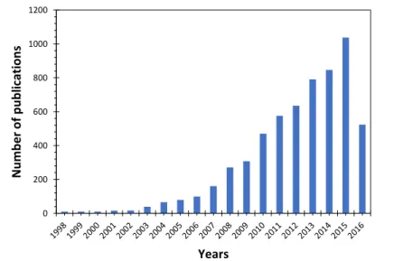
Even if MFC power efficiency is lower than other renewable energy, the valorization of end-life substrates justifies the exponential increase in research publications about MFC and more generally Microbial Electrochemical Technologies (METs) [8].
Figure 1.2 - Number of published journal articles on MFCs containing the phrases “microbial fuel cell”. Source: Web of Sciences on 07/08/2016
1.2.3. Microbial Electrochemical Systems
Microbial Electrochemical System (MES) is a general class of electrochemical systems adapted from the very original class of MFC but with different bacteria localization, separator configuration and applications (biosensing or electrical/chemical production). The application of MES determines if the system consumes or produces electricity (Figure 1.3). They are also
named Microbial Electrochemical Technologies (METs).
Energy productive MES:
(i) Microbial Fuel Cell (Figure 1.3.A) As described in part 1.2.2. and 1.3.1., MFC allows
electrical power harvesting based on carbon source oxidation (electron donor) via bacteria metabolism. Electrons are produced by the respiration and transferred to the anode (final electron acceptor). By this way, a MFC supplies an external device or resistor. [50]
(ii) Biosensor. If a MFC is monitored in a potentiostatic three electrodes configuration (reference electrode, working and counter electrodes), a substrate oxidized by
0 200 400 600 800 1000 1200 Nu m be r o f p ub lic ation s Years
CHAPITRE I,LITERATURE REVIEW−30
bacteria can be dosed electrochemically. Current produced by electrons flow must be precisely measured by a potentiostat (I > 100 pA). [55,56]
(iii) Microbial Remediation Cell. Exoelectrogenous bacteria accept various fuels as carbon source or co-substrate. Similarly to MFC, specific strains named Dissimilatory Metal-Reducing Bacteria (DMRB) are able to couple the oxidation of organic electron donors and reduction of metal pollutants from industry (electron acceptors). DMRB are useful for reduction of heavy metal-ions pollutants. [57–59]
(iv) Microbial Desalination Cell (Figure 1.3.D). Schematically, a MDC is an MFC associated
with a third chamber between anodic and cathodic sides. This chamber is separated into anodic and cathodic chambers with two membranes: an anion-exchange membrane and a cation-exchange membrane. While MDC works, bioelectricity is harvested. Additionally, anions and cations from sea water migrate to the anodic and cathodic side, respectively. [60–62]
Figure 1.3 – Four typical MXC, where X corresponds to application:
(A) Microbial Fuel Cell, adaptable for biosensing; (B) Microbial Electrolysis Cell for hydrogen production; (C) Microbial Electrosynthesis for CO2 valorization; (D) Microbial Desalination Cell, including ionic gradient middle
chamber. Wang H. and Ren Z.J., 2013[8]
Energy consumers MES:
(v) Microbial Electrolysis Cell (Figure 1.3.B). By applying a bias to the MFC, cell voltage
must be enough to work in water splitting mode inducing dihydrogen production (protons reduction). [61]
(vi) Microbial Electrosynthesis, CO2 valorization (Figure 1.3.C). In contrast with other microbial electrochemical systems, MES anodic side is free of bacteria and the cathode is colonized by bacteria able to recover carbon dioxide and convert it into small organic
CHAPITRE I,LITERATURE REVIEW− 31 molecules with electrons provided by the cathode. MES discovery is based on the verified hypothesis of electron flow from an electrode to a bacterium (reverse classical electron transfer). [63–65]
1.3. M
ICROBIAL
F
UEL
C
ELLS
1.3.1. Principle of MFC electricity generation
Microbial Fuel Cell converts chemical energy into electrical energy through metabolic activity of micro-organisms and more particularly bacteria respiration in the case of this thesis work. These bacteria are defined as exoelectrogenic, “exo” for exocellular and “electrogen” to define their ability to produce electricity by transferring electrons to chemical or solid substrate [66]. To compare MFC with a conventional fuel cell, the bacterium acts as a biocatalyst.
Figure 1.4 – Developed scheme of a Microbial Fuel Cell.
Micro-organism (in green) converts glucose into carbon dioxide, protons (diffusing through the membrane to the cathode) and electrons transferred to anode and cathode via external circuit.
Adapted from: Rabaey K., Verstraete W.[67]
Basically, a MFC is composed of an anode in a first compartment, a cathode in another compartment. Both compartments are separated by an ion-permeable membrane. The anode is colonized by bacteria which oxidize fuel (organic matter) in a final product (ex. pyruvate for lactate), electrons, protons and CO2. Such a CO2 production is less damageable than CO2 produced from fossil fuel as it results from biomass conversion. Electrons flow from the anode to the cathode via an external circuit (device or resistor) and protons diffuse through the membrane from the anodic compartment to the cathodic compartment. Most of the time, at the cathode protons and electrons react with oxygen from air leading to it reduction into water
(Figure 1.4) [10,66,67,9,68].
In comparison with enzymatic fuel cell, microbial fuel cell catalysts are easily regenerated by bacteria growth in specific conditions without requiring expensive step of isolation or purification. Moreover, in 2002 Kim et al. studied the lifetime of a MFC under cycling
CHAPITRE I,LITERATURE REVIEW−32
condition beyond 3 or 5 years. The diversity of bacteria able to exoelectrogenic activity in MFC-mode is robust and versatile. Consequently, they present numerous metabolic profitable pathways to generate electricity from a large diversity of electron donors (Figure 1.5). MFC are
less specific than EFC resulting in a higher conversion yield for a complex chemical environment (wastewater, industry effluents, …) [9].
Figure 1.5 – General overview of anodic and cathodic BES/MET (non-exhaustive).
At the anode, simple molecule or gas are oxidized while CO2, H2O, glucose and protons are reduced at the cathode. Reaction in: Purple, do not directly result in current generation. Green, produce energy. Yellow, occur
spontaneously (without bias). Red, require power addition to occur. Bruce and Rabaey[9]
1.3.2. Microbial Electron Transfer
Bacteria are now well-known to transfer electrons obtained by respiration mechanism. This ability to donate electrons to a surface is a critical point in the elaboration of microbial fuel cells and more generally, microbial electrochemical systems. Electron production happens by the oxidation of electron donors (lactate, acetate, glucose, …) inside the cell using bacterial respiration. Resultant electrons flow to electron acceptors (conductive surface, fumarate, …). For the electron transfer to occur, electrons have to cross the cell wall before reducing electron acceptors.
Figure 1.6 – Extracellular electron transfer representation:
Direct electron transfers (DET), mediated electron transfers (MET); indirect electron transfers (IET) are similar to MET using electron donor synthetized by fermentative micro-organisms
CHAPITRE I,LITERATURE REVIEW− 33 Intensive studies about extracellular electron transfer (EET) were carried out in order to better understand transfer pathways. Currently, three types of electron transfer are defined and presented on Figure 1.6: indirect electron transfer (IET), mediated electron transfer (MET) and
direct electron transfer (DET). These transfers are not exclusive and may occur simultaneously depending on bacteria nature. For example, Shewanella oneidensis (S. oneidensis) carries out MET and DET while Geobacter sulfurreducens (G. sulfurreducens) only performs DET.
1.3.2.1. Indirect Electron Transfer.
Most cells and bacteria strains transfer electrons by indirect electron transfer. For IET, fermentative bacteria consume carbon sources and convert it into metabolite products such as hydrogen or alcohol. These fermentative products are redox species in reduced state and contain electrons that can be donated to an electron acceptor. As a matter of fact, they are secreted by bacteria and diffuse to react at the electrode surface.
1.3.2.2. Mediated Electron Transfer.
Mediated transfer is based on the use of soluble intermediate molecules to facilitate electron shuttling from the inside of the bacteria to the outside at the electrode surface. The mediators also named shuttles are redox molecules that approach the cell and diffuse inside to be reduced by electrons from their initial oxidized state to a more reduced one and consequently oxidized again at the electrode. Misunderstanding usually remains on the difference between MET and IET. They are based on the same principle, but in MET, shuttles are reusable intermediates while in IET fermentative metabolites are not (Figure 1.7).
Figure 1.7 – Difference in electron transfer mechanism between IET (a) and MET (b)
Since Potter ambiguous discovery of bioelectricity generation (cf. part 1.2.2) [6], shuttles have been extensively used as electron transfer promotors in MFC due to their high reversibility. Originally, synthetic mediators were added to culture to palliate incapacity of bacteria such as
Escherichia coli to directly transfer electrons [69]. Many artificial redox molecules were
demonstrated to allow MET: neutral red, methyl viologen, methylene blue, AQDS, thionin [67,70– 72] or immobilized mediators at electrode surface [73]. Due to their toxicity and cost, mediators are restricted to isolated experiments and are inefficient if scaling-up is proposed [74]. Moreover, in the early 2000s, Rabaey et al. demonstrated Pseudomonas aeruginosa ability to self-produced pyocyanin as mediators to operate MET without external addition of synthetic molecules [44,45,72,75]. Accumulation of mediators in batch condition was demonstrated to involve electron
CHAPITRE I,LITERATURE REVIEW−34
transfer and bioelectricity generation [76]. On the contrary, changing medium to regenerate carbon source concentration dramatically decreases the monitored current. This observation allows to conclude on the mediator-driven characteristic of Pseudomonas aeruginosa or
Escherichia coli while other bacteria such as G. sulfurreducens presents a membrane-driven
characteristic [67]. For S. oneidensis, both membrane-driven (DET) and mediator-driven (MET, flavin [77–79]) behaviors have been demonstrated.
1.3.2.3. Direct Electron Transfer.
Initially, cells were considered as structure incapable to transfer electrons directly, without the assistance of redox mediators owing to their inherent non-conductive nature. Cell membranes are made off isolative materials such as polysaccharides. But the growth of certain bacteria at the surface of iron or manganese oxides suggested direct interaction between them. Multi-heme c-type cytochrome proteins were suggested as responsible for electron diffusion from the inside to the outside of bacteria through the cell wall [72]. By mutagenesis experiments on genes specific to c-type cytochromes, it was demonstrated that c-cytochromes (localized in the outer membrane, inner membrane and periplasm space) facilitate the interaction between bacteria and metal oxide during dissimilatory metal reduction forming an electron chain transfer (ETC) [80–82]
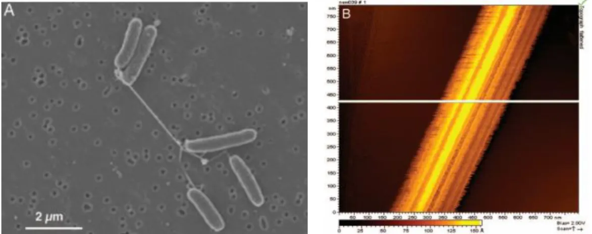
Figure 1.8 – Evidence of nanowires production by S. oneidensis: (A) Scaning electron microscopy of S. oneidensis showing pilus connection between two S. oneidensis bacteria. (B) STM analysis of a single nanowire demonstrating
conductivity in white. Gorby et al. [83]
Considering that membrane-bounded c-cytochromes as open doors for electron transfer, only the first layer of bacteria at the electrode surface must be electroactive. In 2005, Gorby et al. observed connecting pili between S. oneidensis or S. oneidensis and a solid conductive surface. By scanning tunneling microscopy, they demonstrated the conductivity of these thick nanowires (Figure 1.8) [83]. Complementary to these results, in 2010 El-Naggar et al. confirmed previous results by growing S. oneidensis on SiO2 wafer between gold deposited nano-electrodes. It appears that nanowires are conductive and electron transfer is observed at long range scale at a speed of 109 electrons.s-1 (AFM at 100 mV applied) (Figure 1.9) [84]. In 2006, Reguera et al. observed conductive pili production by G. sulfurreducens by atomic force microscopy.
CHAPITRE I,LITERATURE REVIEW− 35
Figure 1.9 – (A) S. oneidensis on nano-fabricated Au/Pt contact. (B) Resistance along conductance appendant. El-Naggar et al. [84]
Two mechanisms are proposed for pili conductivity: (i) metal-like conductivity based on delocalization of electron through π-orbital amino acids conjugation. (ii) electron-hopping conductivity based on the hopping of electrons through c-cytochromes along the pilus. A mutation on the gene which encoded for mtrC and omcA c-Cyts (see section 1.3.3.1) of S.
oneidensis leads to the formation of non-conductive appendage. This suggests that c-Cyt along
pili are responsible for electrical conductivity (electron-hopping conductivity – Figure 1.10.A)[83]. For G. sulfurreducens controversy remains between electron-hopping hypothesis [85] and metal-like conductivity [86,87]. Other authors suggest a mix of both conductivity [88](Figure 1.10).
Figure 1.10 – Representation of proposed mechanisms for electron transfer between the membrane cell and the electrode through conductive nanowires/pili: (A) Electron-hopping through c-Cyt [83,85], (B) metal-like conductivity
by electron delocalization along π-orbital of amino acid conjugation [86,87], (C) Bonanni hypothesis of mixed comportments [88]. Adapted from: Bonanni et al. [88] and Malvankar et al. [89]
1.3.3. Exoelectrogenic bacterium
A large diversity of electroactive bacteria exists and has been referenced for their ability to electron transfer and participates to bioelectricity generation in a MFC system. From the first bacteria that demonstrate self-mediated characteristic (Shewanella putrefaciens IR-1) to the recent extremophiles, G. sulfurreducens, Pseudomonas aerudinosa, Geothrix propionicus, … a large variety of bacteria was highlighted for their performances as biocatalysts [10,9,90]. Microbial fuel cells are based on promoted extracellular electron transfer by bacteria. Three reasons explain why bacteria transfer electrons [10]: (i) Bacterial respiration on metal oxides (Geobacter
(A) (B)
(A) (B) (C)
CHAPITRE I,LITERATURE REVIEW−36
and Shewanella). (ii) Electrons sharing between bacteria, Gorby et al. observed the formation of thick conductive appendages connecting Pelotomaculum thermopropionicum (fermentative bacteria) and Methanothermobacter thermautotrophicus (methanogen bacteria). Gorby hypothesized that bacteria form these conductive structures to support interspecies electron transfer [83]. (iii) Quorum sensing (i.e. inter-bacteria communication) was suggested to enhance electron transfer [91].
1.3.3.1. Shewanella oneidensis.
In 1988, Nealson et al. firstly isolated a gram-negative γ-proteobacteria from sediments of Lake Oneida in New York responsible of the high level of reduced manganese (Mn2+) in water. This bacterium was geographically named S. oneidensis MR-1 for Manganese-Reducing 1. S.
oneidensis is a bacillus bacterium and an optional anaerobic bacterium which grows and survives
in oxygenated medium (Figure 1.11). This strain is classified in the class of Dissimilatory Metal
Reducing Bacteria (DMRB) due to its ability to reduce manganese and few other heavy metals such as iron, uranium or lead [92]. This metal-reducing aptitude comes with its EET conductive network formed by c-cytochromes which present multiple heme in the inner membrane (CymA), the periplasm (MtrA) and outermembrane (MtrC, OmcA). By applying mutation on gene responsible of these c-Cyts, Myers proved their implication in MnO2 reduction (mutants present a reduction-rate 45 to 75% slower than wild type) [82]. Riboflavin was suggested as soluble shuttles by Marsili et al. after experiencing high current drop when biofilm supernatant was removed [77].
Figure 1.11 – Morphology of electroactive S. oneidensis strain on a palladium (a) and gold (b) substrates: with (a) or without (b) formation of conductive pili (red arrow)
1.3.3.2. Pure culture versus mixed culture.
System comparison is challenging due to the advantages and limitations of a large diversity of strategies employed to develop MFC: single or dual chamber, electrode material employed, separator nature. As an example, in 2008, Ishii et al. demonstrated +22% in power density for a mixed culture comparing to a pure culture of G. sulfurreducen (single chamber MFC, air cathode) [93]. In the same time, Nevin et al. emphasized comparable or higher power production for G. sulfurreducens rather than an enriched consortium of bacteria (dual chamber
CHAPITRE I,LITERATURE REVIEW− 37 MFC, ferrycianide cathode) [94]. In addition, Kim and Paraneswaran show that in enriched culture, some bacteria cannot grow by their own without co-cultured strains and support for fuel degradation [42,95].
Moreover, for power harvesting applications, pure cultures appear less efficient than mixed cultures extracted from real media (wastewater, sludge, sewage, …) or artificially composed of bacteria consortia. Single cultured G. sulfurreducens only degrades short organic molecules such as acetate [69]. A large diversity of substrates may be degraded by a consortium and this synergetic behavior allows extracting a higher quantity of energy from a complex medium. On the contrary, pure cultures are efficient to observe specific bacteria-electrode interactions or bio-energy production mechanisms and to understand how to optimize the overall MFC.
1.3.4. Biofilm
A biofilm consists in surface-associated pure or mixed bacteria embedded in a self-produced extracellular polymeric substance (EPS) [96] composed of DNA, proteins, polysaccharides and electron transfer facilitators (redox shuttles, …) [97–99]. Microbial species close to the electrode surface are engaged in an adhesive structure. Unlike isolated planktonic cells also named “floating cells” which mainly transfer electron by MET, bacteria forming biofilm may transfer electrons by MET and DET pathways [45,100]. They form community where micro-organisms communicate in a balance of cooperation and competition [101]. It is important to notice that all bacteria are not electroactive in both pure or mixed biofilms (Figure 1.12). Certain
bacteria are inactive (represented in brown) but secrete molecules which facilitate EET or break massive organic matters into more adapted fuels for exoelectrogenic bacteria (Figure 1.12) [10].
Figure 1.12 – Bacteria forming communities at the electrode surface engaged in: (A) membrane-bounded C-Cyt DET, (B) pili DET, (C) MET. Inactive bacteria are represented in brown, DET-engaged bacteria in green and purple,
MET-engaged bacteria in blue (shuttles diffusing in red). Logan et al. [10]
A biofilm forms a complex architecture changing as a function of metabolic, physiological and ecological states. While biofilms enhanced electron transfer [102,103] due to potential conductive facilitators (c-Cyt, nanowires, shuttles), diffusion can be slowed down by the biofilm tortuosity and compactness. The loss of fuel diffusion deeply into the biofilm as well as acidification due to entrapped protons may cause the decline of biofilm activity and current generation [104,105]. Biofilm can exceed 50 to 80 µm thick, this structure presents cells engaged in electron transfer, cooperative cells forming a compatibilizing environment for exoelectrogenic
CHAPITRE I,LITERATURE REVIEW−38
bacteria and competitive cells [106]. Moreover, dynamic nature of biofilm causes its formation, degradation and regeneration engaging MFC performances.
1.4. M
ICROBIAL
F
UEL
C
ELLS
E
FFICIENCY
:
KEY FACTORS
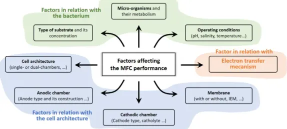
Efficiency of microbial fuel cells depends on many parameters to optimize cell voltage, current and power density. In comparison with standard fuel cells or enzymatic fuel cells, microbial fuel cells performance depends on the metabolic activity of a micro-organism which adds more complexity to perform MFC optimization. Relevant factors that affect MFC efficiency are related to the global cell conception and architecture, the electronic transfer at bacteria-electrode interface and the inherent metabolic activity of the bacterium (Figure 1.13) [107].
The performance of a microbial fuel cell is described by polarization and power curves (potential and power in function of current) commonly used for classic fuel cells [108]. A polarization curve can be divided in three main domains of low (zone A), intermediate (zone B) and high (zone C) relative density of current (Figure 1.14). As an initial approach, each domain
is specifically affected by the factors stated above.
Figure 1.13 – Factors affecting the performance of the MFC. Adapted from: Aghababaie et al. [109]
(A) At low current, the system is theoretically governed by Nernst and Buttler-Volmer
equations. At the open circuit current (i=0), the OCP is defined by the redox potential of the species responsible for the electronic transfer. Therefore, the bacterium nature, its metabolic activity and pathways efficiency to transfer electrons are determinant. Activation losses are predominant and occur during the electron transfer from the bacterium to the electrode by the intermediate of a mediator (if needed). These losses may be minimized by improving the electrode surface (high surface area, roughness, catalyst) and by the formation of an adapted, conductive biofilm. For low current, an over-potential results from activation losses which affects the anode potential: 𝐸𝑎=
𝐸𝑒𝑞− 𝜂𝑎.
(B) At intermediate current, the internal resistance becomes damageable resulting in
predominant ohmic losses. Therefore, the cell voltage linearly decreases following the ohmic low: 𝐸 = 𝐸𝑖=0− 𝑅
CHAPITRE I,LITERATURE REVIEW− 39 to (i) electron flow through the electrode, interconnection and external circuit; (ii) ions flow through both anodic and cathodic electrolyte (ionic strength) and the ion exchange membrane (if present). An effective mean to decrease ohmic losses is to control the MFC architecture by using highly conductive electrodes materials, low resistive membranes or a membrane-less reactor, by increasing ionic strength of the electrolytes (in function of the bacterium tolerance) and by ensuring that all contacts are not limiting electron flow.
(C) At higher current concentration losses are mainly due to a low rate of mass transport.
The fuel is limited by diffusion gradients which lead to a lack of nutrients and mediators through the as-formed biofilm and an accumulation of protons in the biofilm and the anolyte. The lack of diffusion of proton and species to reduce (O2) leads to a decrease of the number of exchanged electrons in the system and high degradation at the limiting current of the cell.
Figure 1.14 – Polarization and power curves: the working point is defined as the cell voltage and the current density for the maximum power density provided by a fuel cell.
1.4.1. Factors related to the bacterium
To elaborate a microbial fuel cell, the choice of the bacterium is important. Two main factors have to be considered: its ability to generate bioelectricity and its electron transfer pathways. Numerous strains are reported and classified including consideration of electron transfer pathways. As examples, Saccharomyces cerevisae, Escherichia coli, Actinobacillus
succinogenes, Proteus mirabilis and Vulgaris or Pseudomonas fluorescence are not able to
transfer electrons by DET (cytochrome, pili) and require a mediator. On the contrary, Rhodoferax
Ferrireducens, the families of Shewanella, Geobacteraceae and Geobacter work without
addition of mediator and transfer electron by DET and/or MET (self-production of shuttles). As previously described, it appears that real or mounted consortia of bacteria produce more energy rather pure culture. This observation is explained by a complex synergetic effect: in a consortium, a chain reaction of degradation (a bacterium degrades a nutrient and produces a
A
A
A
B
C
ACHAPITRE I,LITERATURE REVIEW−40
suitable product for the metabolism of another bacterium, etc.) is established [110]. This process maximizes the energy recovered for a quantity of fuel [10,109].
The choice of the fuel is determinant. A large diversity of pure nutrients (glucose, lactate, acetate, butyrate, …) as well as real or formulate fuels (organic, chemical, industrial wastewaters, …) were tested in MFC based on specific strains or consortia [109]. The fuel choice is complex and has to be done in relation with the selected bacterium or consortium of bacteria. For example, the energy recovered by dissimilatory iron-reducing bacteria from acetate (non-fermentable electron donor) is 66% higher than butyrate [111]. Also, Lee et al. indicates a low conversion of glucose by G. sulfurreducens (3%) in comparison with the higher conversion rate of acetate by the same strain (42%) [112]. More recently, Speers and Reguera confirmed that lactate-fed G. sulfurreducens produce less power than acetate-fed bacteria. Speers and Lee demonstrated that a bacterium metabolism accepts various nutrients, but as function of the encoded enzymes, an electron donor is more suitable than another one. For example, G.
sulfurreducens encodes for glycolate oxidase which poorly degrades lactate while S. oneidensis
encodes for lactate dehydrogenase which efficiently converts lactate [113]. For consortia, real fuels are preferable due to their complex composition presenting a large diversity of nutrients as well as bacteria strains. Moreover, nutrient concentration affects power production. Jiang showed that increasing nutrient concentration from 100 to 850 mg.L-1 rises power output from 0.2 to 1.2 W.m-3 (single-chamber MFC, air-cathode, inoculum: wastewater) [114].
1.4.2. Factors related to the cell architecture
Most of the ohmic losses are related to the cell architecture. As described in part 1.4, electrodes materials have to be highly conductive, porous, to present a large surface area and to facilitate both bio-reaction at the anode (adhesion of bacteria, no toxicity, …) and the reduction at the cathode (combustive choice, catholyte, catalysts, …). Space between the electrodes must be optimized as well as their dimension, to limit internal resistance due to diffusion rate and reaction rate. Wang and Zuo demonstrated an increasing of cathode performance as well as specific surface area or geometric surface area, respectively [115,116]. The separator intensively participates to the cell internal resistance. Several tests were done to determine its effect; they showed higher power and current density in absence of membrane. However, the membrane acts as a separator and prevents both chambers to be poisoned. Global cell architecture and the mode of cycling (batch or continuous-fed modes) may influence ohmic losses, mass transport rate and therefore the fuel cell performance.
1.4.3. Factors related to the electronic transfer
The electrons produce by a bacterium are transferred by two mains pathways: DET or MET (cf. 1.3.3). For DET transfer, the bacterium must be in contact with the electrode or close to the electrode to produce a conductive appendage from its membrane to a conductive surface. High surface area is necessary to promote bacteria adhesion in direct contact. For MET, a mediator is mandatory. This mediator is synthetized by the cell or added to the medium. In both cases, shuttles have to meet few requirements: (i) oxidized and reduced forms should easily diffuse through the bacterial membrane, (ii) the redox potential of the mediator should match
CHAPITRE I,LITERATURE REVIEW− 41 the electron transfer potential (electron transfer chain). Both redox states of the shuttle (iii) must not interfere with metabolic activity of the bacterium, (iv) must be chemically stable and soluble (no precipitation inside or outside of the cell). (v) Electrochemical kinetics of oxidation and reduction for the mediator should be fast [21].
1.5. M
ICROBIAL
F
UEL
C
ELLS
M
ATERIALS
&
A
RCHITECTURE
In term of materials and cell designing, three major points must be taken in account to elaborate a MFC: (i) the anode and cathode materials, (ii) the separator between each compartment and (iii) the global architecture of the MFC. Intensive survey concerning materials and cell engineering leads to a great diversity of systems.
1.5.1. Anode materials
To be selected as an effective electrode (anode and cathode), materials must be chosen considering a balance of required properties. High (i) conductivity, (ii) specific surface area, (iii) porosity, (iv) low sensibility to corrosion and bio-corrosion, (v) non-clogging or fouling by bacteria, EPS (exopolysaccharides) and resultant reduced metals are mandatory as inherent properties for MFC stability and efficiency. To ensure bacteria viability and colonization, electrode must be (vi) cytocompatible and non-toxic (for colonized electrodes). To be easily scalable at larger sized, electrodes have to be (vii) inexpensive, widely available and easy to made.
1.5.1.1. Carbon-based materials.
Carbon rods and carbon sheets (flat graphite) are widely used as anodic electrodes in MFC due to their high conductivity, biocompatibility, non-toxicity, chemical stability and low sensibility to corrosion. There are accessible, easy to use and cheap [50,117–119]. To enhance bacterial adhesion, rods are gently abraded to improve their roughness. Main drawbacks of carbon rods and sheets are due to their low specific surface area and low porosity. However, if compactness is not mandatory, inexpensive and mechanically resilient carbon rods and sheets remain materials of choice. Also, carbon rods are commonly considered as model materials [120].
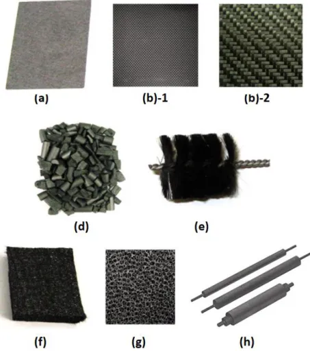
To palliate these issues, more technical 2D and 3D commercial carbon architectures
(Figure 1.15) were used leading to a large diversity of systems [121,122]:
(i) Carbon papers (TorrayTM paper) [122–124] are made by precipitating thin layers of carbon powder (or wide fibers) supplemented or not with a binder on PTFE substrate. They are porous, rigid, easy to connect but brittle and highly expensive (around 1000 dollars/m²).
(ii) Carbon cloth, tissue, mesh [125] consist in wide woven carbon fibers (micrometric, ca. 10 µm). They are flexible, robust and present a higher specific surface area and porosity than carbon papers but are as expensive.
CHAPITRE I,LITERATURE REVIEW−42 (iv) Graphite granules [127–130] consist in micrometric pieces of conductive carbon (activated or not). In a MFC, graphite granules are compacted to ensure electrical contact between individual granules.
(v) Graphite fibers brush [131]. This electrode is made of wide carbon fibers radially assemble around a titanium stem (collector). This brush presents a high specific surface area but they are easy to clog and quite uneasy to entirely colonize.
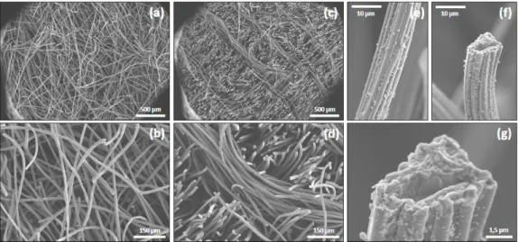
(vi) Carbon and graphite felt [118,127,132,133] consists in a 3D organization of randomly align fibers (ca. 12 µm in diameter). This smooth structure is largely open resulting in a high porosity and specific surface area (ca. 0.2 m².g-1).
Chaudhuri et al. compare carbon rods and felts in a two-chambers MFC using
Rhodoferax Ferrireducen as anodic micro-organism revealing current three time higher
for felts compared with rods. This current increase appears related to the higher specific surface area (x3) and bacteria quantity at the surface (x2.7) [118].
(vii) Carbon foams (Reticulated Vitreous Carbon, RVC) [121] present similar porosity to carbon felts. However, its structure made of rigid interconnected carbon walls (sponge structure) is less resistant than carbon felts and more expensive.
Figure 1.15 – Photograph of various carbon-based electrode materials for MFC: (a) carbon paper (type TorrayTM), (b)-1 carbon cloth, (b)-2 carbon mesh, (d) carbon granules, (e) carbon fibers brush, (f) carbon felt, (g) carbon foam
![Figure 1.20 – Glucose/MnO2 full-MFC [172] . (a) Scheme of the MFC, glucose is microbially oxidized at the anode (mediator: 2-hydroxy-1,4- naphthoquinone) and (b) manganese oxide microbially mineralized is reduced at the](https://thumb-eu.123doks.com/thumbv2/123doknet/7765530.255868/49.892.149.743.718.923/glucose-microbially-oxidized-mediator-naphthoquinone-manganese-microbially-mineralized.webp)