HAL Id: tel-01917775
https://hal.archives-ouvertes.fr/tel-01917775
Submitted on 14 Dec 2018HAL is a multi-disciplinary open access archive for the deposit and dissemination of sci-entific research documents, whether they are pub-lished or not. The documents may come from teaching and research institutions in France or abroad, or from public or private research centers.
L’archive ouverte pluridisciplinaire HAL, est destinée au dépôt et à la diffusion de documents scientifiques de niveau recherche, publiés ou non, émanant des établissements d’enseignement et de recherche français ou étrangers, des laboratoires publics ou privés.
Style and Meta-Style : Another way to reuse Software
Architecture Evolution
Adel Hassan
To cite this version:
Adel Hassan. Style and Meta-Style : Another way to reuse Software Architecture Evolution. Software Engineering [cs.SE]. Universite de Nantes, 2018. English. �tel-01917775�
T
HESE DE DOCTORAT DE
L'UNIVERSITE
DE
NANTES
COMUE UNIVERSITE BRETAGNE LOIREECOLE DOCTORALE N°601
Mathématiques et Sciences et Technologies de l'Information et de la Communication
Spécialité: Génie logiciel Par
« Adel HASSAN »
« Style and Meta-Style: Another Way to Reuse Software Architecture
Evolution»
Thèse présentée et soutenue à « L2SN », le « 24 Septembre 2018 »
Unité de recherche : Laboratoire des Sciences du Numérique de Nantes (LS2N) Thèse N° :
Composition du Jury:
Président
Mme Isabelle BORNE, Professeur, Université Bretagne Sud M. Kamel BARKAOUI, Professeur, Le Cnam-Paris
M. Henri BASSON, Professeur Université du Littoral Côte d'Opale M. Djamel SERIAI, Maître de conférences, HDR, Université de Montpellier
M. Christian ATTIOGBE, Professeur, Université de Nantes Directeur de thèse
M. Mourad OUSSALAH, Professeur, Université de Nantes
Rapporteurs avant soutenance :
M. Kamel Barkaoui, Professeur, Le Cnam-Paris M. Henri Basson, Professeur Université du Littoral Côte d'Opale
ii
Dedication
I dedicate this dissertation to my
beloved parents, wife and kidsAdel
iii
Acknowledgments
First of all, I would like to express my sincere gratitude and appreciation to those who over the years have played a role in the realisation of this thesis.
Many thanks go to Professor, Mourad Oussalah, the director of my thesis for his input and guidance during these years. Without his patience, support and encouragement, this thesis would not have been possible. I also want to thank Audrey Queudet for her guidance and her valuable comments that helped me in realising Chapter 5.
I am further grateful to my thesis monitoring committee, Professor Philippe Collet and Professor Kamel Barkaoui for all their guidance and feedback throughout this process.
I would also like to thank Professors. Isabelle Borne, Henri Basson, Djamel Seriai, Kamel Barkaoui and Christian Attiogbé for accepting membership of my Jury Committee during my viva voce examination.
My sincere thank also goes to all the wonderful staff of LS2N (LINA) for their hospitality and their technical and administrative help.
iv
Contents
Chapter 1. Introduction ... 1 1.1 Context ... 1 1.2 Challenges ... 2 1.3 Contribution ... 3 1.4 Thesis Structure ... 4 1.5 Publications ... 5Chapter 2. Software Architecture and Software Evolution ... 6
2.1 Software Architecture ... 6
2.2 Architecture modeling concepts ... 9
2.3 Architecture Description Languages (ADLs) ... 13
2.4 Architecture Knowledge ... 14
2.5 Meta-modeling in software architecture ... 15
2.6 Software evolution ... 17
2.7 Laws of software evolution... 18
2.8 Dimensions of Software Evolution ... 19
2.9 Evolution as part of the development process ... 21
2.10 Evolution and software architecture ... 22
2.11 Software architecture evolution ... 22
2.12 Conclusion ... 23
Chapter 3. Evolution Styles ... 24
3.1 Process modeling ... 24
3.1.1 Domain Specific Modeling ... 24
3.1.2 SPEM 2.0 ... 25
3.1.3 Essence 1.0 ... 27
3.2 Software architecture evolution modeling ... 28
3.3 Evolution style ... 29
3.3.1 Garlan et al Evolution Style ... 29
3.3.2 Cuesta et al. Evolution Style ... 31
3.3.3 Oussalah et al. Evolution Style ... 32
3.4 Conclusions ... 34
v
4.1 Introduction (Model-Based Engineering) ... 35
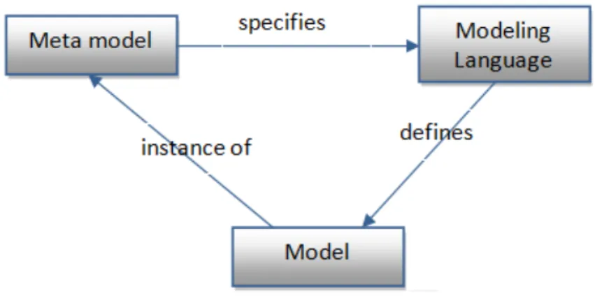
4.2 Model, Modeling Language and the Meta-model ... 35
4.3 Metamodeling ... 37
4.3.1 Meta-Object Facility MOF ... 38
4.4 Metamodeling in software-architecture evolution ... 39
4.4.1 The basic concepts of architecture evolution ... 41
4.4.2 Evolution Meta-Style MES ... 42
4.5 Meta-style based Transformations ... 45
4.5.1 Vertical Mapping ... 46
4.5.2 Horizontal Mapping ... 52
4.6 Mapping scenario ... 58
4.6.1 Modeling an evolution style by Eclipse Process Framework (EPF) composer ... 58
4.6.2 The Result of the Mapping Scenarios ... 65
4.7 Conclusion ... 66
Chapter 5. Dynamic Evolution Meta-Styles ... 67
5.1 Introduction ... 67
5.2 Real-time system ... 67
5.2.1 Types of real-time systems ... 68
5.2.2 Types of real-time tasks ... 69
5.2.3 Architecture Description Languages for real-time system ... 70
5.3 Dynamic software evolution ... 71
5.3.1 Introducing changes at runtime ... 72
5.3.2 Activeness of changes ... 73
5.4 Dynamic software evolution issues ... 74
5.4.1 Safe stopping ... 74
5.4.2 State Transfer ... 75
5.4.3 Change management ... 76
5.4.4 Dynamic evolution scheduling ... 76
5.5 Dynamic evolution of software architecture ... 77
5.5.1 Dynamism in Architecture Description Languages (ADLs) ... 78
5.5.2 Dynamism in component-based software engineering ... 79
5.5.3 Comparison of architecture-centric dynamic evolution approaches ... 83
vi
5.7 Conclusion ... 90
Chapter 6. Multi-View in Evolution Meta-Styles ... 91
6.1. Introduction ... 91
6.2. Multiple views in Software Requirements Specification (SRS) ... 92
6.3. Multi-view in system modeling ... 94
6.4. Multi-view in Software architecture ... 96
6.5. Compression of multi-view architecture frameworks ... 104
6.6. Multi-view & multi-abstraction evolution styles ... 106
6.6.1 Evolution style (Model) ... 107
6.6.2 Viewpoint and view ... 108
6.6.3 Abstraction levels ... 109
6.7. Multi-view and multi-abstraction-level evolution meta-style ... 109
6.8. Mapping MES+ to standard ... 111
6.8.1 UML concepts for MES+ ... 113
6.9. Conclusion ... 114
Chapter 7. Development of multi-view modeling tool for SAE ... 115
7.1. Introduction ... 115
7.2. Motivation for new tool ... 115
7.3. Domain-specific (Modeling) Languages DSLs ... 116
7.3.1 Frameworks for Implementing DSLs ... 117
7.4. Multi-view Evolution-Style Model ... 119
7.5. Prototype implementation on the ADOxx platform ... 122
7.5.1 ADOxx Metamodeling Platform ... 122
7.5.2 The MES+ multi-view/abstraction modeling tool development ... 124
7.6. Conclusion ... 128
Chapter 8. Conclusions & Future Work ... 129
8.1 Conclusions ... 129
vii
List of Figures
Figure 1: A group of architectural elements can be depicted using an ADL ... 9
Figure 2: Four levels of modeling in software architectures ... 16
Figure 3: The implementation of the four modeling levels in software architecture ... 17
Figure 4: Themes and dimensions of software change. ... 20
Figure 5: The staged process model for evolution (adapted from (Yau, Collofello, and MacGregor 1978)) 21 Figure 6: Overview of key concepts in SPEM 2.0 ... 26
Figure 7: Essence Methods architecture (taken from REMICS) ... 27
Figure 8: Overview of key language concepts in Essence [REMICS] ... 28
Figure 9: Depiction of an evolution style ... 30
Figure 10: Screenshot of the Ævol workbench... 31
Figure 11: Presentation of evolutions pattern ... 32
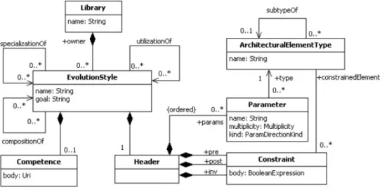
Figure 12: Meta-model of the concept of evolution style... 33
Figure 13: Modeling language ... 36
Figure 14: Metamodeling ... 37
Figure 15: Four-layer Metamodeling Architecture ... 38
Figure 16: Four Layer Meta-Style Architecture ... 40
Figure 17: The basic concepts of evolution styles ... 41
Figure 18: Evolution Meta-Style MES ... 43
Figure 19: Metamodel for an evolution style ... 44
Figure 20: Mapping between evolution style and MES ... 45
Figure 21: The conception of models mapping ... 47
Figure 22: Metamodel for Garlan style ... 48
Figure 23: Mapping Garlan style to MES ... 48
Figure 24: Metamodel for Cuesta et al. evolution styles ... 50
Figure 25: Mapping Cuesta et al. evolution style to MES ... 50
Figure 26: SAEM metamodel... 51
Figure 27: Mapping Oussalah et al. evolution style to MES ... 52
Figure 28: Mapping MES with MOF ... 54
Figure 29: Mapping MES with MOF ... 56
Figure 30: Method Framework of EPF ... 58
Figure 31: Screenshot of EPF composer ... 60
Figure 32: The representation of evolution operator in EPF composer ... 61
Figure 33: The representation of evolution state in EPF composer ... 62
Figure 34: The representation of architect in EPF composer ... 63
Figure 35: Screenshot of a published evolution style ... 64
Figure 36: Artifact state transactions ... 75
Figure 37: Themes and dimensions of software change ... 83
Figure 38: Reference model ... 84
viii
Figure 40: Multi-view and multi-abstraction evolution style ... 107
Figure 41: MES+ ... 110
Figure 42: IEEE-42010 standard model ... 111
Figure 43: An evolution-style meta-model in MSDK ... 118
Figure 44: An evolution-style editor implemented on MSDK ... 119
Figure 45: Evolution-path view ... 120
Figure 46: An architecture-evolution decision view ... 121
Figure 47: Roles and languages in the modeling hierarchy of ADOxx ... 123
Figure 48: Modeling and Relation Classes definition in ADOxx ... 125
Figure 49: Realisation of evolution style’s views ... 126
Figure 50: AttrRep definition ... 127
ix
List of Tables
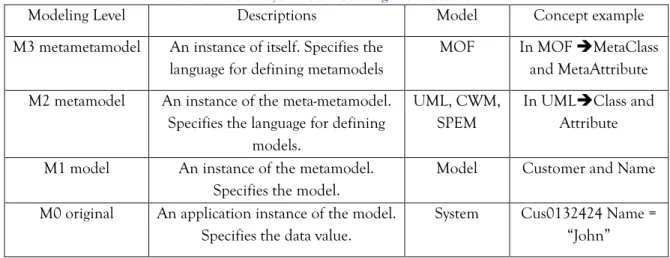
Table 1: Four-layer metamodeling architecture ... 39
Table 2: Conformation of MES with a proposed style ... 44
Table 3: Equivalent elements between MES and Garlan et al. evolution style ... 49
Table 4: Equivalent elements between MES and Cuesta et al. evolution styles ... 51
Table 5: Equivalent elements between MES and SAEM ... 51
Table 6: MES mapping with MOF ... 55
Table 7: MOF instantiation ... 56
Table 8: Matching MES with SPEM ... 57
Table 9: Garlan style, SPEM; corresponding elements ... 57
Table 10: Mapping Garlan style to EPF Composer ... 60
Table 11: Comparison of some dynamic component-base frameworks ... 85
Table 12: Comparison of dynamic evolution approaches ... 90
Table 13: The architecture views of the Zachman Framework ... 96
Table 14: The architecture views of Kruchten model... 97
Table 15: The architecture views of the Siemens model. ... 98
Table 16: The architecture views of the SEI ... 98
Table 17: The architecture views of the Garlan and Anthony approach ... 99
Table 18: The architecture views of the Rozanski and Woods approach ... 100
Table 19 : The architecture views of TOGAF ... 101
Table 20: The architecture views of ISO 42010:2011 ... 101
Table 21: The architecture views of the common architecture-view model ... 102
Table 22: The architecture views of MoVAL. ... 103
Table 23: The architecture views of EPART ... 104
Table 24: A comparative analysis between some multi-view frameworks of architecture approaches. ... 105
Table 25: Corresponding elements between MES+ and IEEE-42010 ... 112
Table 26: Mapping MES+ - UML ... 113
Table 27: Mapping of the MES concepts to the ADOxx concepts ... 124
1
Chapter 1. Introduction
1.1 Context
Nowadays, information systems are becoming more and more complex and more widely distributed, with most being software-intensive systems. They often include large-scale heterogeneous distributed software components, embedded systems, telecommunications, wireless ad hoc systems etc. As markets and technology are continually changing, these systems also need to change in order to fulfill the new requirements of the market and technology. Whenever a system needs to be changed, the ideal starting point for the evolution team is to understand the system (design) and then to attempt to find a suitable set of modifications. In this context, planning the large-scale evolution is a highly challenging activity that requires an understanding of the overall system structure, consideration of pervious design decisions, and principled trade-offs among candidate evolution scenarios and selecting the optimal scenario (Barnes, Pandey, and Garlan 2013).
One of the main difficulties of software evolution lies in the fact that all artifacts produced and used during the entire software lifecycle are subject to changes (Buckley et al. 2005). Since software systems change fairly frequently, and all software artifacts are subject to change, it is essential that their architectures must be restructured. However, software architecture is the backbone of the software system (Taylor, Medvidovic, and Dashofy 2009) and plays a key role in guiding software development and evolution. Thus, architectural changes are inevitable for a software system in order to guide the evolution process, or prevent architectural drift and erosion, and maintain the system’s consistency (to avoid inconsistency between the architecture and source code over time). In this vein, the role of software architecture in the software evolution process can be considered from two points of view: as an artifact for evolution, which guides the planning and conducting of the evolution process, and as an artifact of the evolution, because it must be evolved itself in order to be consistent with system change (Cuesta et al. 2013).
In practice, the architecture of a software system is the first design artifact which captures those early architectural decisions which had a significant impact on the quality of the system. Whenever this system needs to change, it is important, if not essential, to understand these decisions as early as possible in the evolution process. However, architecture evolution is about making new design decisions, or removing obsolete ones, in order to embrace the new requirements. It concerns the changes applied to the architecture, including their components, connectors or configuration. In fact, software architecture evolution is a very complex process to plan and thus the person or team who plays this role should have a blend of architectural knowledge from different fields including: business architecture, enterprise architecture, data architecture, application architecture and infrastructure or technical architecture.
2 Therefore, the architects are in needs of tools, methods and techniques that help them to prevent the evaporation of the architectural evolution knowledge (Oussalah et al. 2006). This is especially true in regard to the sharing and reuse of this knowledge by those architects who do not have such experience.
This thesis focuses on both software architecture evolution knowledge modeling and on reusing. It aims to explore the best techniques for capturing the architectural evolution knowledge and practices, allowing these to be demonstrated in fashions that can fit the different type of stakeholder involved in this process. This solution must take into account the existing evolution styles and standards and, thus, they can be reused and exploited.
The structure of this chapter is as follows: Section 1.1 introduces the context of this work, Section 1.2 elaborates on the questions that this work endeavours to address, Section 1.3 presents the research contribution, and Section 1.4 summarises the structure of the thesis.
1.2 Challenges
Reuse has formulated the optimal goal of several methodologies proposed and used in software product engineering. It varies from fine products, such as objects or methods, to very large and complex products, such as components or architecture styles. For software process engineering, especially here in the software architecture evolution process, the reused parts can be operations, activities, steps, a solution or even a set of possible solutions (to evolve the current architecture towards the intended target architecture).
Evolution style is one of software engineering approaches, the aim of which is to enhance reuse in the software architecture evolution knowledge. The main idea behind the evolution styles is to capture and share the best architectural evolution practices and knowledge relevant to a particular domain. To this end, they model the possible evolution scenarios that represent different ways of evolving this domain. These modeled scenarios can be grouped together into an evolution style that the architect can compare and analyse in order to plan and reason about software evolution. Several evolution styles have been introduced, each of which defines their own method and tool to depict the process using a relevant modelling technique (notions, syntax and semantic) in accordance with a certain point of view (Hassan and Oussalah 2016). Notwithstanding all these considerable achievements, some important issues related to standardisation and reuse among evolution styles themselves are still absent and need more exploration.
To address this limitation, this thesis considers the common existing approaches to both process and product modeling (MOF, UML, SPEM and Essence) and evolution styles (Hassan and Oussalah 2016), and provides a meta-style evolution (meta-meta-model) and methodology for software architecture evolution modeling. To this end, some issues have to be addressed:
We need to define a meta-style evolution which can specify all necessary (meta-) elements (the meta-modeling language) that can instantiate the elements of the evolution styles.
3 It is necessary to validate the ability of the meta-style evolution in terms of conforming to the different evolution styles and managing the mapping among these styles. Moreover, it is necessary to explore the extent to which this meta-style is equivalent to common standard models.
We need to assess the extent to which this meta-style can be extended to embrace new aspects of the evolution process (e.g. dynamism) or a new mechanism of modeling this process (a new stakeholder perspective).
The proposed meta-style and methodology should be implemented in order to explore the feasibility of the approach.
This thesis endeavours to explore all these concerns and to provide a framework that can support reuse in software architecture evolution.
1.3 Contribution
The main contributions of this thesis are:
Proposition of a meta-meta-model for software architecture evolution: We introduce The MES (meta-style evolution) component-oriented framework. It is a reflective methodology whereby the notion of the component reflects on the modeling of the process that evolves it. Thus, the component is the main entity of the MES model, as in the object-oriented modeling in which everything is subclass of the abstract class “ModelElement”. Mapping procedures have been conducted with some standard models and evolution styles, the aim of which is to allow transformation between different evolution styles themselves as well as to the discipline of object modeling.
Extension of Meta-style evolution: We have extended the MES with some concepts that allow for modeling dynamic evolution in software architecture. We explore some issues that accompany dynamic evolution, such as: safe stopping, state transfer, change management and dynamic scheduling. This is done in order to annotate MES with the information required to fit the analysis and model the dynamic evolution of software architecture.
A methodology for multi-view/abstraction evolution style: We present a methodology in which the architect (modeler) of an evolution style can decompose an evolution style into different views and abstraction-levels. Several views of the process can be produced which cover different irrelevant perspectives separately and fit a wide range of stakeholders.
Implementation of a prototype tool supporting the proposed meta-style and methodology: In order to validate the applicability and feasibility of our approach, an initial tool prototype was developed, based on the conception of MES. To demonstrate this tool, a set of proposed views has been developed and integrated, in according to the relation notion introduced in MES.
4
1.4 Thesis Structure
The remainder of this document is organised as follows.
Chapter 2.
Software architecture and software evolution: In this chapter, we present thebackground and the relevant realms of this work: Software Architecture (SA), Software Evolution (SE) and Architecture and the Software Architecture Evolution (SAE). We begin with a historical overview of the important definitions of software architecture and the terminology used in this field. In the second part of this chapter, we discuss the concept of software evolution, its motivations (the laws of software evolution) and the dimensions of software evolution. The third part handles the relationship between software evolution and software architecture. From this overview the importance of software architecture in guiding the planning and restructuring of the software system become clear.
Chapter 3.
Evolution styles: This chapter presents the state of the art related to our work software architecture evolution modelling “evolution styles”. In the first part, we position the evolution styles’ realm, including some meta-modelling approaches in software process engineering. The second part presents a review of the on evolution styles and explores these approaches form different perspectives: conceptual, theoretical and practical. The objective of this chapter is to analyse the important research approaches in software architecture evolution, especially in sharing and reusing architectural knowledge and practices in the modeling of this process.Chapter 4.
Evolution Meta-Style: This chapter presents our first important contribution:Meta-style evolution which is a meta-meta model for software architecture evolution modeling. The first part is described the meta-modeling methodology, along with the benefits of this methodology and an example of The Meta-Object Facility MOF. The second part exploits this methodology in the domain of evolution style and, thus, Meta style and its main concepts are defined. The last part of this chapter puts MES in the mapping process as a means of evaluation.
Chapter 5.
Dynamic Meta-Style Evolution: This chapter discusses the issues of dynamicevolution and looks at how these issues are handled at the architecture level. The objective is to extract necessary concepts and information that need to be annotated with MES in order to fill the requirement of modeling the dynamic evolution of software architecture.
Chapter 6.
Multiple views/abstractions with Meta-style evolution: This chapter introduces thenotion of multi-view and multi-abstraction modeling into the domain of evolution style. The first part presents a summary of the literature associated with this notion of view/viewpoint in the discipline of computer science. The second part represents our contribution in which we integrate these notions into the Meta-style evolution.
Chapter 7.
Prototype: The chapter presents an initial prototype tool, implementing a multi-viewevolution style editor based on the meta-style evolution specification. To implement the prototype, the ADOxx Meta-modeling platform has been selected as a development toolkit. Four different types of views are developed to visualise architectural evolution knowledge: path view, component-connector view, deployment view and decision view. The last part of this chapter presents a scenario of realisation an evolution style model on the initial prototype tool.
5
Chapter 8.
Conclusions: This chapter summarises the contribution of the thesis and thelimitations of the proposed approach, and outlines future work that would formulate possible directions for future research.
1.5 Publications
The following publications present some of the results represented in this thesis:
International conference
[1]. Adel Hassan and Mourad Oussalah. "Evolution Styles: Multi-View/Multi-Level Model for Software Architecture Evolution." 7th ACM International Conference on Software and Computer
Applications. 2018.
[2]. Adel Hassan, Audrey Queudet, and Mourad Oussalah, "Evolution style: framework for modeling dynamic evolution of real-time software architecture." 10TH EUROPEAN
CONFERENCE ON SOFTWARE ARCHITECTURE (ECSA 2016). 2016.
[3]. Adel Hassan, Mourad Oussalah, “Meta-evolution style for software architecture evolution” 42th International Conference on Current Trends in Theory and Practice of Informatics. Springer, Berlin, Heidelberg, SOFSEM 2016.
International journal
[1]. Adel Hassan, Mourad Oussalah, "Evolution Styles: Multi-View/Multi-Level Model for Software Architecture Evolution," Journal of Software vol. 13, no. 3, pp. 146-154, 2018.
6
Chapter 2. Software Architecture and Software
Evolution
This chapter relates the work in this thesis to background realms and is divided into a number of sections, including software architecture, software evolution and software architecture evolution, as well as software process models. In each section, there is also an explanation of how the thesis is related to each paradigm
2.1 Software Architecture
Software architecture serves as a blueprint for a software system's construction and evolution (Garlan 2000), (Clements, Garlan, Bass, et al. 2002). It is the backbone of the software system (Taylor, Medvidovic, and Dashofy 2009). In the last years, several definitions of software architecture have been published, although it was first defined by Perry and Wolf as a 3-tuple consisting of Elements, Form, and Rationale in 1992.
Elements capture the system‘s building blocks, which can be of three types: processing elements, data elements and connecting elements.
Form captures how the (architectural) elements are organized in the architecture, by means of weighted properties and relationships. That is, the form captures how the elements are composed (i.e. the architecture configuration), the characteristics of their interactions, and their relationship with their operating environment.
Rationale captures the motivation for the choice of an architectural style, the choice of elements, and the form. That is, the system designer‘s intent, assumptions, choices, external constraints, selected design patterns, and other information that is not easily observable from the architecture.
(Perry and Wolf 1992)
In 1993, Shaw and Garlan argued that software architecture represented a problem of designing and specifying the overall system structure that was beyond the algorithms and data structures of the computation. These structural issues include: gross organisation and global control structure; protocols for communication, synchronisation and data access; the assignment of functionality to design elements; physical distribution; the composition of design elements; scaling and performance; and selection among design alternatives. Based on this the authors define the term “architectural style” as denoting a family of architectures that share a common vocabulary (of components and connectors) and meet a set of constraints for that style.
An architecture of a specific system is a collection of computational components or simply components together with a description of the interactions between these components the connectors.
7 These definitions are some of the most widely extended and accepted definitions of software architecture. Over the years, other researchers have refined and extended these early classical definitions and several definitions have been presented based on them. One of these extended definitions was proposed by Garlan and Perry for their guest editorial in the April 1995 IEEE Transactions on Software Engineering, devoted to software architecture:
The structure of the components of a program/system, their interrelationships, and principles and guidelines governing their design and evolution over time.
(Garlan and Perry 1995)
Another extended definition was proposed by Kruchten in 1995:
Software architecture deals with the design and implementation of the high-level structure of the software. It is the result of assembling a certain number of architectural elements in some well -chosen forms to satisfy the major functionality and performance requirements of the system, as well as some other, non-functional requirements such as reliability, scalability, portability, and availability.
Software architecture deals with abstraction, with decomposition and composition, with style and esthetics. (Kruchten 1995a)
Another definition that considers the needs of stakeholders (users, acquirers, analysts, developers, testers, maintainers, inter-operators, and others) as a concept necessary for complete software architecture is that of Gacek et al.:
A software-system architecture comprises:
a collection of software and system components, connections and constraints; a collection of system stakeholders’ need statements;
a rationale which demonstrates that the components, connections, and constraints define a
system, that if implemented, would satisfy the collection of system stakeholders’ need statements (Gacek et al. 1995)
Another definition introduced by Shaw and Garlan in 1996, implicitly includes the elements defined by Perry and Wolf:
Software architecture involves the description of elements from which systems are built, interactions among those elements, patterns that guide their composition, and constraints on these patterns.
(Shaw and Garlan 1996)
Bass, Clements and Kazman, in 1998 proposed a definition of software architecture whereby they insisted on the external visible properties of the elements defining their expected behaviour:
The software architecture of a program or computing system is the structure or structures of the system, which comprise software elements, the externally visible properties of those elements, and the relationships among them.
8 Another definition was provided by the ANSI/IEEE Standard 1471-2000. It presents a conceptual framework and embodies a theory and practice of architectural descriptions (AD). It includes the use of multiple views, reusable specifications for models within views, and the relationship of architecture description to system context. This conceptual framework is introduced via a class diagram (meta-model) with a set of content requirements for the architecture description and its context (views, viewpoints, stakeholders and concerns).
Architecture is the fundamental organization of a system, embodied in its components, their relationships to each other and the environment, and the principles governing its design and evolution.
(Maier, Emery, and Hilliard 2001)
One of the more interesting extended forms of Perry and Wolf is provided by Taylor, Medvidovic and Dashofy, who embrace the meaning of What, How and Why questions:
Elements help to answer the What questions about the architecture: What are the elements of a system? What is their primary purpose and the services they provide?
Form helps to answer the How questions about the architecture: How is the architecture organized? How are the elements composed to accomplish the system‘s key task? How are the elements distributed?
Rationale helps to answer the Why questions about the architecture: Why are particular elements used? Why are they combined in a particular way? Why is the system distributed in a given manner?
(Taylor, Medvidovic, and Dashofy 2009)
Finally, there is one more definition by Taylor, Medvidovic and Dashofy in their book: Software Architecture: Foundation, Theory and Practice. They state that the system architecture represents the set of principal design decisions which depend on the system goals defined by the stakeholders (as requirements drive architecture). The definition places the software architecture as a central artifact in the software life-cycle which is specified in the early stages of software development and which constitutes the process model:
A software system’s architecture is the set of principal design decisions about the system.
Design decisions encompass every aspect of the system under development, including: system structure, functional behavior, interaction, nonfunctional properties and implementation.
Principal is a term that implies a degree of importance and topicality that grants a design decision architectural status, that is, that makes it an architectural design decision (i.e. it impacts a system’s architecture).
(Taylor, Medvidovic, and Dashofy 2009)
None of these definitions conflict with each other. Instead, they are similar in that they are all concerned with the structure and behaviour of the system. “Structure” describes how the system is built of interconnected elements called components. “Behavior” refers to the visible interaction of these components in order to achieve the overall system’s functionality. Both the structure and
9 behaviour of software architecture are formally described using Architecture Description Languages (ADLs).
2.2 Architecture modeling concepts
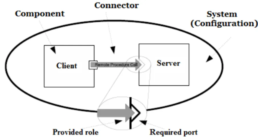
Generally, the overall ADLs defined to date according to Taylor and Medvidovic (Medvidovic and Taylor 2000), focus on the basic component, the connector, the interface and the configuration. All of these treat components as first-class citizens, but in some languages neither the connector nor the architectural configuration are considered first-class citizens. In order to facilitate a better comprehension of the work of this thesis, we are presenting a precise definition of the most relevant concepts, some of which are represented in Figure 1.
Figure 1: A group of architectural elements can be depicted using an ADL
Component
The component represents the basic concept of software architecture and of the first-class citizens that Architecture Description Languages (ADLs) share par excellence. Szyperski is one of the leading authors on component software:
A software component is a unit of composition with contractually specified interfaces and explicit context dependencies only, a software component can be deployed independently and is subject to composition by third parties.
(Szyperski 2002) A software component is a decoupled architectural entity which provides functionality and/or a
data source. It can be deployed independently or within a software system. A server, database or mathematical functions are examples of components. A component should contain three constituents: interfaces, an implementation and a descriptive specification (Taylor, Medvidovic, and Dashofy 2009).
10 The interface is the port of the component that defines the points of interaction with its environment (Szyperski 2002). Furthermore, a component may have multiple interfaces (ports), separated into two main categories: provided and required interfaces. “Implementations” refer to the concrete, executable code of components that are defined by the developer and hidden behind the interfaces. “Specification” defines the component’s semantics as a set of functional and non-functional properties (external definition), based on which the component can be reused (selected).
Connector
Connectors identify the interaction between the components and correspond to lines in box-line descriptions. The connector may play one role or many different roles, in a system, each of which is identified by the service that the connector provides. These services belong to one of four categories: communication, coordination, conversion and facilitation (Mehta, Medvidovic, and Phadke 2000). It is possible to have a multi-category connector in order to serve different interaction requirements. These four categories have been further classified into eight types, depending on the way in which they realise interaction services: procedure call, event, data access, linkage, stream, arbitrator, adaptor and distributor. Perry has provided a high-level classification of the roles that software connectors play in architecture (Perry 1997). Mary Shaw was the first to introduce explicit connectors that separate the concerns of computation, handled by components, from inter-component communications, handled by connectors.
Connectors are the locus of relations among components. They mediate interactions but are no ”things” to be hooked up (they are, rather, the hookers-up). Each connector has a protocol specification that defines its properties. These properties include rules about the types of interfaces it is able to mediate for, assurances about properties of the interaction, rules about the order in which things happen, and commitments about the interaction, such as ordering, performance, etc
(Shaw 1993)
Shaw presents the connector as an architectural element that defines the coordination process among components. The separation between the interaction and the computation is promoted so as to obtain more reusable and modularised components (the same component can be used in a variety of environments, each of which uses different communication primitives) and to improve the level of abstraction of the software architecture descriptions. Furthermore, it provides an architectural view of the system instead of the object-oriented view of compositional approaches. Shaw also defends the idea of considering connectors as first-class citizens of software architecture in terms of their description languages (Shaw 1993).
Allen and Garlan (Allen and Garlan 1997) formalise the semantics of connectors, whereby the specification of the connector types is based on the idea of characterising the protocols of interaction (interaction patterns) between architectural components. In general, connectors represent mechanisms for transferring control and data around a system (Lau, Elizondo, and Wang
11 2005). Each of these mechanisms has specific characteristics and properties. Examples of connectors are: procedure call, sending events, pipes and data stream. A procedure call can be local or remote. In the case of remote, various kinds of remote procedure calls (or remote method invocation) middlewares can be used to implement such a call (Java RMI, DCOM, CORBA, SOAP, etc.).
Software architecture represents the structure and behaviour of software systems. It captures the behaviour of a software system from the behaviour of individual components and how they interact with each other. Thus, interaction is the central focus of software architecture (Kiwelekar 2013).
Several ADLs have introduced the concept of connectors as first-class entities, such as ACME (Garlan, Monroe, and Wile 2000), Wright (Allen 1997), Archware (Oquendo et al. 2004), π-ADL (Oquendo 2004) and COSA (Smeda, Oussalah, and Khammaci 2004), whereas for example, Darwin language uses implicit connections. The connections among components are specified in terms of direct bindings of requires and provides interfaces.
Configuration
An architectural configuration (a system's instance or topology) is a graph which shows how components and connectors are composed in a specific way in order to accomplish the system‘s objectives. “The basic elements of architectural description are components, connectors and configurations “(Garlan, Allen, and Ockerbloom 1994).
An architectural configuration is a set of specific associations between the components and connectors of software system architecture.
(Taylor, Medvidovic, and Dashofy 2009)
The graph is obtained via associating the ports of the components with the roles of the appropriate connectors, in order to formalise the system (or subsystem). The associations among components and connectors are sometimes called attachments (in the same composite and binding among different levels).
Oussalah et al. in different works, COSABuilder (Smeda et al. 2008) and C3 meta-model (Amirat and Oussalah 2009), defines configuration as a first-class citizen like the component and the connector. He argues that, since a component and connector are perceived and handled from the outside as primitive elements, their inside may be composite with a configuration which constrains the wiring of all the internal elements. This configuration should be also handled as a first-class entity. It represents a graph of components and connectors and describes how they are fastened to each other. Configuration can be hierarchical where each component and connector represents a sub-configuration that has internal architectures. So, they do not treat the configuration as an instance of a system but as an architecture “Type” which can be also instantiated.
12
System
A system is a collection of components and connectors instantiated in a configuration. This
definition, unlike others definitions (e.g. Oussalah) which consider the configuration as another kind of architectural element, defines the configuration only as an instance of a system. Therefore we can state that the concept of system here differs from the concept of configuration in that a system is a building block that can be reused in several software systems, whereas a configuration defines a specific instance of a system which cannot be reused.It is often represented as a hierarchical network (i.e. a composition may be composed of other subsystems) of components linked together by connectors in accordance with a certain set of rules, which facilitates the understandability and the specification of the architectural description. Several ADLs have introduced the concept of the system as a configuration of components and connectors, such as UniCon, Wright, Acme and Archware.
Interface
An interface is the "gate" to the outside world, made up of components, connectors and configurations. It is also known as a port for components and configurations and as a role for connectors. The interface (port) of a component provides the information (services) that allow use of the component without knowledge of its implementation. In addition to the services provided by component, the interfaces also specify the services required by the component. Require interfaces declare the operations that allow the component to interact accurately with its environment. Thus, the component can have multiple ports which either provide or require services to/from its environment.
A connector consists of a set of roles. Each role serves as a connection point that defines the behaviour of one participant in the interaction. The role is also either a provided role or the required role. A provided role serves as an entry point to a component interaction and is intended to be connected to a required interface of a component (or to a required role of another connector).
Interactions between interfaces are defined by attachments and bindings.
Attachment: represents the connection of a port of a component and a role of a connector, if they are
compatible with each other (required / provided).
Bindings establish the mappings between the internal and external interfaces of a system (Garlan,
2001).The connections between the ports (or roles) of a system, or of a composite component and the ports (roles) of one of its architectural elements. Thus the binding is different from attachments because binding represent a hierarchical composition mechanism, used between different granularities, while attachments are a flat composition mechanism, used among the same granularity.
13
Other concepts
Even though, the previous concepts are adequate for describing a software architecture, there are other relevant concepts which have been added by most ADLs, or which are common to software architecture that remain to be defined.
First there are the concepts of Architecture Style which are widely used in order to represent families of software architecture descriptions that belong to software systems which have something in common: resource types, configuration patterns and constraints (Garlan 2002). Examples of styles are: event-based, layered, blackboard, pipe-and-filter, client-server, peer-to-peer etc.
In addition to the aforementioned high-level elements, most architecture also associates properties with their internal elements. For example, for an architecture in which its components are associated with periodic tasks, the properties could define the periodicity, the priority, and the worst case execution time of each component. Properties may also be non-functional, such as the relative ease of evolution, the reusability of components, the efficiency and the dynamic extensibility, and these are often referred to as quality attributes (Bass, Clements, and Kazman 1998).
A Type is another concept that simulates the paradigm of object and class. A type can be instantiated several times in the same architecture, or can be reused in other architectures. A system with explicit types (such as pipes, filters, clients, servers, parsers, databases etc) facilitates understanding and allows analysing of the architectures (Garlan, Allen, and Ockerbloom 1994). Thus, it is possible to reuse components, connectors and configurations by component types, connector types, and configuration types. In this regard, an architectural style can be seen as a particular type of configuration.
The last concept that we aim to mention is that of the Constraints which express the restrictions on the architectural elements. They are often applied to an architectural design in order to induce the architectural properties desired of the system. For example, the uniform pipe-and-filter style obtains by constraining the components to a single interface type. Thus, any single “port” of a filter can be connected to one pipe at most. The constraints can be specified either in a separate constraint language (such as Architecture Constraint Language ASL and Object Constraint Language OCL) or directly by ADLs such as Aesop, SADL and Wright.
2.3 Architecture Description Languages (ADLs)
According to the standard (ISO/IEC/IEEE 42010, 2011), an Architecture Description Language (ADL) is:
“Any form of expression for use in architecture descriptions”.
Box and line have for a long time, been the only means for informally describing software architecture. Occasionally, it is useful to have a formal description that can assist in understanding
14 the alternatives and trade-offs of the design decisions. Nevertheless, the continual increase in the size and complexity of software systems have drawn a lot of interest in develop more rigorous ways for describing software architecture. Thus, architecture description languages (ADLs) overcome the informality of most box-and-line descriptions of software architecture, and provide notations and tools for accurately representing the structures and behaviours of the architecture and for supporting the reasoning (architecture knowledge) about them (Clements 1996). In this vein, a prominent thread of research on formal ADLs has been conducted over the past two-and-a-half decades (Garlan 2014), with the definitions of dozens of different of ADLs. Accordingly, a number of ADLs have been developed by the academic community for modeling architectures, both within a particular domain and as general-purpose architecture modeling languages. Some of the prominent ADLs proposed include Darwin (Magee and Kramer 1996), Rapide (Luckham and Vera 1995), UniCon (Shaw et al. 1995), Wright (Allen 1997), Acme (Garlan, Monroe, and Wile 2000), Koala (Van Ommering et al. 2000), xADL (Dashofy, Van der Hoek, and Taylor 2001) , ArchWare (Oquendo et al. 2004), UML 2 (Ivers et al. 2004), AADL (Feiler, Gluch, and Hudak 2006) and COSA (Smeda, Oussalah, and Khammaci 2004). Each of these ADLs comes with certain distinctive capabilities (Medvidovic and Taylor 2000), such as multi-view, dynamism and analysis mechanisms. Some of these ADLs are domain-specific, for example: AADL, SysML1 and EAST-ADL (Cuenot et al. 2010) which have been presented to deal with real-time and embedded computer systems; DiaSpec (Cassou et al. 2009) used for control-loop applications; Koala used for product-line architectures; π-ADL (Oquendo 2004) used for dynamic and mobile software architectures, and ArchiMate, used for enterprise architecture.
2.4 Architecture Knowledge
Whenever a software system needs to be modified, it must be understood in the first step, before non-destructive modifications can be proposed or enacted. Measurements have shown that system comprehension consumes more than half of the time and effort of the evolution (Gacek et al. 1995), (Zelkowitz, Shaw, and Gannon 1979).
As mentioned before, Perry and Wolf in (1992) provided one of the most insightful definitions of software architecture, defining it as a 3-tuble of element, form, and rationale. Even though, the concept of rationale is missing in some definitions such as that of Garlan and Shaw (1993), it reflects the essence of the software architecture. It aims to answer the Why questions about architecture design decisions in accordance with the What, How and Why of Taylor, Medvidovic and Dashofy’s definition of software architecture (Taylor, Medvidovic, and Dashofy 2009). Capturing the architecture decisions can help to get into the architects’ reasoning process, reduce knowledge vaporisation and avoid architectural drift.
1 https://www.omg.org/spec/SysML/1.5.
15 Jansen and Bosch emphasised this view, and this was shown in their definition of software architecture as a composition of a set of architectural design decisions (Jansen and Bosch 2005). In accordance with this point of view, a different software architecture paradigm emerged, which represents the software architecture from the point of view of its stakeholders (concerns, design decisions, alternatives, rationale) (van Heesch et al. 2014), rather than from the physical view (structure and behaviour).
Thus, different research into capturing, modeling sharing, and (re)using architecture knowledge have been conducted, whereby several architecture knowledge managements methods, techniques, and tools have been proposed in order to support the decision-centric architecture approaches (Capilla et al. 2016). In this thesis, we are more interested in capturing design decisions throughout the architecture life-cycle and thus enabling the management of its advanced evolution processes.
2.5 Meta-modeling in software architecture
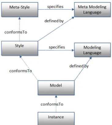
Meta-modeling is a modeling technique that aims to manage the complexity of a system, enhancing the understandability and promoting standardisation and interoperability. It has been widely used to address real problems in programming languages, databases, engineering models or distributed systems. However, it often defines two or more levels using the definition of a metamodel (Oussalah 2014). Meta-knowledge is knowledge about knowledge and meta-model is modeling of model. Based on this view, meta-architecture is the act of architecting (modeling) applied to the architecture. This mechanism can be applied several times yielding multiple levels of modeling. One prevailing framework that implements the four modeling levels was proposed by the Object Management Group (OMG). Oussalah et al. (Smeda, Oussalah, and Khammaci 2005) argued that the meta-modeling technique could be applied to the field of software architecture (i.e. it could be implemented in the component- based modeling like on the object-oriented approach). Based in this view, they used this technique to define Meta Architecture Description Language (MADL). Accordingly, an architecture hierarchy with four modeling levels was defined, starting from a meta-meta-architecture and going up to an application level. Moreover, COSA Builder, as ADL tool based on this language, was developed. Figure 2 illustrates the MADAL construction which applied the meta-knowledge to the field of architecture. It identifies four levels of modeling: the meta-meta-architecture level, the meta-meta-meta-architecture level, the meta-meta-architecture level and the application level.
The meta-meta-architecture level (A3): this level provides the minimum components for modeling architecture, which represent the basic concepts for an ADL. The meta-meta-architecture is an instance of itself (self-defined).
The meta-architecture level (A2): this level provides the basic modeling components for an architecture description language (ADL) – component, connector, architecture, ports, roles, etc. by which a system architecture can be defined. Meta-architecture conforms to the
meta-meta-16 architectures (its meta). Each element in the A2 level is an instance of an element (its meta-element) in the A3 level.
The architecture level (A1): at this level, several types of components, connectors and architectures can be described. Each architecture model should comply with its meta-architectures (ADL), whereby each element of A1 is associated with an element of A2.
Figure 2: Four levels of modeling in software architectures
The application level (A0): This level refers to the place where the executive units are located. An application is considered as a set of instances of architecture-element types. Applications conform to the architecture whereby each element of A0 is associated with an element of A1.
Some advantages of introducing the multi-level (meta-modeling) in the domain of architecture have been summarised as follows:
The architecture can play a vital role in standardisation among their instances as a meta-architecture can semantically conform to different meta-architectures.
The meta-architecture can support the reuse in the definition of new architecture (instantiates new architecture).
The meta-architecture can provide the foundation for comparison and mapping among different architectures.
The meta-architecture facilitates and supports the exchange of architectural elements between the ADLs.
This view of software architecture will be seen as important when the problem of the evolution of software architecture is discussed in the next chapter, for example in distinguishing the granularity of changes, i.e. the changes impacting architecture type (level) and/or architecture instance. Figure 3 represents an example of these modeling levels applied to client-server architecture.
17 Figure 3: The implementation of the four modeling levels in software architecture
2.6 Software evolution
Change is inevitable for any software system in order to achieve its business goals during its lifetime. The necessity and the characteristics of software change are defined as Lehman's laws of software evolution (Lehman 1996). During the last 40 years, many empirical studies have been conducted to address the validity of these laws (of software evolution). Herraiz et al. (Herraiz et al. 2013) summarised these studies and found that all of them have validated the first law ‘’Law of
Continuing Change: An E-type system that is used must be continually adapted else it becomes progressively less satisfactory.” It can be stated that systems must be evolved continuously in order to be useful, -
i.e. evolution is a recurrent process that accompanies a system from its initial creation to its eventual retirement or abandonment. However, several studies have suggested that software evolution consumes the largest share of the software life-cycle budget (50% to 90%) (Moad 1990) and (Erlikh 2000). This confirms the need for techniques, methods and tools that guide the different participants in the software evolution process. Different approaches have been suggested
18 to facilitate and support such software evolution (Mens, Serebrenik, and Cleve 2014). Lehman provides the following definition of evolution:
“Software evolution is the collection of all programming activities intended to generate a new version from an older and operational version.”
(Lehman 2000)
2.7
Laws of software evolution
The laws of software evolution were formulated by Lehman et al. and the first version was based on the observations of the IBM OS/360 operating system (Lehman 1974). Initially, Lehman defined three basic principles for the evolution of software systems. He uses the term “E-type software” to denote programs that address a problem or an activity of the real world. Accordingly, changes in the real world will necessitate changes in the software which serves this environment. The laws of software evolution, then, have seen several refinements over the years, with the most recent version of the laws published in 1996 (Lehman 1996) and summarised as follows:
Law of Continuing Change:
An E-type system that is used must be continually adapted, else it becomes progressively less satisfactory in use.
Law of Increasing Complexity:
As an E-type system evolves, its complexity increases unless work is done to maintain or reduce the complexity.
Law of Self-Regulation:
Global E-type system evolution processes are self-regulating. Law of Conservation of Organisational Stability:
Average global activity rate in an E-type process tends to remain constant over periods or segments of system evolution.
Law of Conservation of Familiarity:
The average growth rate of E-type systems tends to remain constant or to decline. Law of Continuing Growth:
The functional capability of an E-type system must be continually increased to maintain user satisfaction over its lifetime.
Law of Declining Quality:
Unless rigorously adapted to take into account changes in the operational environment, the quality of E-type systems will appear to be declining.
Law of Feedback System:
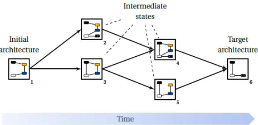
19 The laws concerning continuing change, increasing complexity, and continuing growth are of particular interest for this thesis. However, the ever-changing requirements of technology and the business environment necessitate integrating new features or improving the quality of the system for it to remain useful. Changes cannot be made over-night, so the evolution team must develop a plan to manage and conduct this process. In fact, the ideal start for the evolution team is to understand the system and then to find a suitable set of system modifications. Then, the optimal scenario, which best fits certain properties, will be selected. Ultimately, implementation of the selected scenario will lead to the new target system through a series of phased releases. All these have motivated this work, i.e. when evolving a system, it is important to explore the potential selections of evolution, to understand the rationale of these scenarios and to make trade-offs among them. Our thesis aims to investigate this trade at the architectural level. This is based on the fact that, architecture evolution is an essential complement to software evolution because it permits planning and system restructuring at a high level of modeling where business goals, quality requirements and alternative scenarios of evolution can be explored (Barnes, Garlan, and Schmerl 2014).
2.8 Dimensions of Software Evolution
Software evolution is a complex process, due to the fact that all artifacts produced and used during the software development life-cycle are subject to changes, starting from requirements, through analysis and design documents to the executable code. All these have inspired several studies about the dimensions and taxonomies of software change (Lientz and Swanson 1980), (Chapin et al. 2001), (Buckley et al. 2005), all of which attempt to answer the Why, How, What, When and Where of software evolution.
Lientz and Swanson (Lientz and Swanson 1980) proposed a mutually exclusive and exhaustive software maintenance typology, falling into three basic categories, namely perfective, adaptive and corrective. This definition was further extended by the ISO/IEC Standard for Software Maintenance (ISO 1999) to include the category of preventive maintenance activities. This typology was further refined by Chapin et al. (Chapin et al. 2001) into an evidence-based classification to include 12 different types of software evolution and software maintenance.
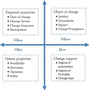
A few years later, a more complex taxonomy of evolution was proposed by Buckley et al. (Buckley et al. 2005), which focuses more on the characteristics of software change mechanisms and the factors that influence these mechanisms. Several dimensions were refined into four logical themes: temporal properties (When is the change made?); object of change (Where is a change made?); system properties (What is being changed?); and change support (How is the change accomplished?), as shown in Figure 4.
However, the dimensions of evolution are classified as characterising the mechanism or as influencing factors. An influencing factor, for example, a system’s ‘availability’ can be affected by the change mechanism applied to that system. If a system is required to be highly available, then a
20 run-time change mechanism should be applied. The characteristics of software change are those factors of software change which can be used to describe the nature of the changes (e.g. “time of change”).
Figure 4: Themes and dimensions of software change.
In order to facilitate a better comprehension of the work of this thesis, the theme “object of change” is presented in more detail here. This theme describes the location(s) in the system where changes are made, divided into four factors:
Artifact: refers to any produced and/or used artifact during the entire software development life-cycle which may be subject to change, ranging from requirements through architecture and design, to source code, documentation, configurations and test suites.
Granularity: refers to the scale of the artifacts to be changed and can range from very coarse (system architecture), through medium (modules/components), to a very fine degree of granularity (class, methods).
Impact: The impact of a change, ranging from local to system-wide change, which can span different artifacts with different abstraction levels (from source code to architecture).
Propagation: refers to the process of ensuring that a change with global impact is propagated to all related entities in the software system. Propagation can be performed in two directions; horizontal or vertical (top-down or bottom-up).
Each of these dimensions can be affected by the others. For example, if we take system architecture as an artifact of change, the evolution mechanism of this artifact can be affected by other factors from the same or from another, theme. The impact of change at the architecture can vary from the small scale of a component to the entire architecture (system/configuration). Moreover, the impact
21 of change can remain within the same abstraction level of the architecture (vertical impact), or span across different levels (horizontal impact).
Propagation at the architecture artifact also can be performed in two directions, whereby vertical propagation affects the same abstraction level and horizontal propagation is done across different architecture levels (top-down or bottom-up), from an architecture type to its instance or vice versa. The time-of-change dimension at the architecture evolution, can widely affect the mechanism of the changes, arranging them from static, through load-time, to dynamic (at runtime). Dynamic evolution refers to modifying the architecture and enacting those modifications in the system without halting the system. This is a critical requirement for many software systems, such as air traffic control, telecommunications and financial systems (Hassan, Queudet, and Oussalah 2016).
2.9 Evolution as part of the development process
The term “software evolution” refers to a phase of the software life cycle, which lasts from the initial creation of the software product until its eventual retirement or abandonment (close down phase). Several factors, such as frequency, effort and cost of changes have promoted evolution to be an important stage in the life-cycle of a software product. Based on this view, several software development methods have been introduced and gained widespread acceptance in the research community. Each of these methods has the evolution as a crucial stage of the process model. Some examples are: Evolutionary Development (Gilb 1981), the Spiral Model (Boehm 1988), Staged Model (Rajlich and Bennett 2000), and Agile Software Development (Cockburn 2001). In these models, the stage of software evolution can involve the adaptation of new requirements or the performance of maintenance activities.
Evolution planning is often the first phase of software evolution and often starts with analysing the change impact and checking the completeness and consistency of the intended design. This step requires a deep understanding of the system (design decisions) and of the changes (suitable modifications) in order to satisfy the evolution requirements without breaking the existing functionality (loss of design quality). Based on these perspectives, one of the first attempts to move towards a more evolutionary model was proposed by Yau et al. (Yau, Collofello, and MacGregor 1978) with the so-called change mini-cycle which consists of the five main phases shown in Figure 5.