OATAO is an open access repository that collects the work of Toulouse
researchers and makes it freely available over the web where possible
Any correspondence concerning this service should be sent
to the repository administrator:
[email protected]
This is an author’s version published in: http://oatao.univ-toulouse.fr/24280
To cite this version:
Salem, Mohamed Medhat and De Luycker, Emmanuel and
Fazzini, Marina and Ouagne, Pierre Experimental, analytical
and numerical investigation to prevent the tow buckling defect
during fabric forming. (2019) Composites Part A: Applied
Science and Manufacturing, 125. 1-13. ISSN 1359-835X
Official URL:
https://doi.org/10.1016/j.compositesa.2019.105567
Open Archive Toulouse Archive Ouverte
Experimental, analytical and numerical investigation to prevent the tow
buckling defect during fabric forming
☆
M.M. Salem, E. De Luycker
⁎, M. Fazzini, P. Ouagne
Laboratoire Génie de Production (LGP), Université de Toulouse, INP-ENIT, Tarbes, FranceA R T I C L E I N F O Keywords: Fabrics/textiles (A) Defect (B) Mechanical testing (D) Numerical analysis (C) A B S T R A C T
We investigate the causes, kinematic and possible ways to prevent the tow-buckling defect during the complex shape-forming of a dry woven reinforcement. Macro-scale compression leads to wrinkles; we focus on a meso-scale phenomenon generated by a non-uniform axial compression of the tow due to in-plane bending. An ex-perimental study is presented, followed by an efficient method to predict the onset of the tow-buckling defect. This investigation is based on the combination of an experimentally validated analytical approach, with a macro-scale simulation of the forming process for a single fabric layer. A particular focus is given to the resulting tow curvatures that allows us to predict the zones of high tow buckling probability. The relatively simple numerical approach based on Lagrange assumptions does not take into account tow slippage. However, for most cases, where buckles appear before slippage, this approach alleviates the compulsory need for an expensive meso-scale representation.
1. Introduction
Fiber reinforced structural composites offer great mechanical per-formances because of their low density compared to regular structural materials. Manufacturing such parts requires the use of a fibrous re-inforcement. Among others, woven fabrics represent a large amount of the chosen reinforcement due to their high drapability, good perme-ability and good cohesion when subjected to multidirectional loading and high manufacturing processability[1]. However, defects that may jeopardize the mechanical integrity of the composites could appear, prior to resin injection, during the complex shape forming of woven reinforcements such as the resin transfer molding (RTM) process, as identified by Potter et al.[2].
Some of these defects, such as the preform wrinkling, have been extensively investigated in the literature. Several experimental in-vestigations[3–5]and numerical investigations [6–8]led to the un-derstanding of the mechanics behind the formation of the wrinkling defect and the ways to prevent it (blank holders design, ply orienta-tions, etc.).
Other defects mentioned by Potter et al.[2]remain to be fully un-derstood, such as, tow sliding/unweaving as experienced in[4,9,10] and studied in[11,12]or the tow buckling defect.
The tow buckling defect was defined by Ouagne et al.[10,13]as a
tow deflection out of the plane of the reinforcement by a few milli-meters combined with a rotation around its axis. Capelle et al.[14] designed a special set of blank holders associated with a tetrahedral punch to limit the appearance of tow buckles. Tephany et al.[15]and Ouagne et al.[16]found from their preliminary study the causes that could lead and influence the tow buckles appearance. The said causes could be linked to the previously mentioned ways to prevent the wrinkling defect. A device was designed to recreate the conditions of the tow buckling defect and investigate the causes. They concluded, that the most influencing parameters are the in-plane bending of the tow, the reinforcement orientations and the applied loads in both warp and weft directions of the reinforcement. However, some other geo-metric and mechanical parameters were not investigated. Beakou[17]
and Matveev[18]described a comparable phenomenon on carbon tape
during the automatic layup process. They deducted that the lateral buckles are a result of the dissymmetrical in-plane longitudinal com-pression load generated in the tape via in-plane bending; they proposed an analytical solution to predict its appearance.
This work sets itself as a follow-up of Tephany’s work[15]and a more in-depth investigation of the effects of tensile loads, nature and geometrical parameters of the tows on the tow buckling defect. Our aim is to better understand the defect appearance and the possibilities to prevent it. In conjunction with an experimental study, the analytical
⁎Corresponding author.
E-mail address: [email protected](E. De Luycker). https://doi.org/10.1016/j.compositesa.2019.105567
via each of the jaws bolts. The lateral jaws can then follow an in-plane circular translation motion as illustrated byFig. 1(b, d).
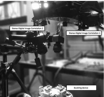
In addition to the two load sensors that allow tension measure-ments, the device is instrumented with two Stereo Digital Image Correlation systems (S-DIC), as shown inFig. 2, associated with the
Fig. 1. Principle of the tow-buckling device: (a) kinematic diagram of the initial state of the device, (b) kinematic diagram of the bent state of the device, (c) picture of the device in the initial state, (d) picture of the buckles on the surface of the reinforcement. (For interpretation of the references to color in thisfigure legend, the reader is referred to the web version of this article.)
Fig. 2. S-DIC setups with the buckling device. model proposed in [17,18] was modified so that to predict the
ap-pearance of tow buckling in the woven fabric reinforcements. This paper is divided in two parts: the first one dealing with experimental investigation and the second one presenting the analytical modeling and the possibility to predict the tow buckling appearance during the forming of a complex shape, such as a prismatic shape, using an iso-geometrical simulation. The aim of our numerical work is in the same vein as the work of Iwata et al. [19]; predicting defects appearance. The chosen numerical approach is much simpler though with the known limitations of macro-scale modeling which are unable to consider tow slippage contrary to meso-scale modeling. An isogeometrical frame-work is chosen for its capability to naturally evaluate the curvatures along the tows during a simulation. The main advantage here is the computational efficiency of the macro-scale description since no con-tact is computed within the fabric. Only concon-tacts between the fabric and the tools are considered. It is therefore possible to perform such simu-lations on a laptop computer and it permits investigating a possible prediction of the tow buckling defect.
2. Experimental study
2.1. Materials and experimental setup
For this study, the same device (Fig. 1) as the one described in [19,20] was used and modified. The device permits to impose different initial tensile loads in warp and weft directions of a woven fabric as represented in Fig. 1(a, c). The loads can therefore be applied in the fixed longitudinal tow network (direction 1, load 1) and in the trans-versal tows network submitted to in-plane bending (direction 2, load 2)
software GOM ARAMIS®. The first set of S-DIC set retrieves global in-formation at the scale of the whole device (Fig. 3(a)) and the second one focuses on the formation of the tow buckles locally (Fig. 3(b)). The in-plane bending state of the reinforcement is evaluated in two ways. A global way via a so-called “bending angle of the device” defined in Tephany[15], as presented inFigs. 1(b) and3(a), assuming that an originally straight tow rotates rigidly. A local way by extracting the curvature radius, using ImageJ® software, from the fabric images of Fig. 3(b).
In order to evaluate the buckling behavior of a tow within a fabric, at each bending state, its most deflecting profile is extracted from the 3D reconstructed upper surface of the fabric (Fig. 4(a)). The different states of the same profile are then compiled inFig. 4(b). The red curve inFig. 4(b) represents thefinal state of the profile of the buckled tow at a bending angle of ~40°.
In order to determine the causes for the tow buckling defect, pre-viously stated parameters such as tensile loading and bending angle were investigated more in depth alongside other fabric geometrical parameters such as the tow free dimensions and the tows nature. The tow free dimensions are the unsupported (free-floating) length and width of the apparent portion of the tow that is expected to buckle as
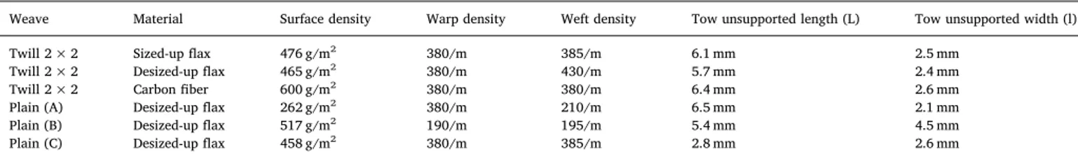
illustrated inFig. 3(b). Several reinforcements, with similar tow widths and/or unsupported lengths, were considered. Reinforcements such as flax fabrics, manufactured specially in the frame of a previous project by Groupe Depestele (France), and a carbon fabric (HexForce 48,600 U 1250) manufactured by Hexcel (France) and which characteristics are listed inTable 1.
2.2. Experimental results
2.2.1. Effect of the tows dimensions and fabric construction
To determine the effect of the tow geometrical properties,
re-inforcements manufactured with the same tows but different weaves
were selected. This allows us to vary the tow unsupported length and width independently from other parameters. The selected reinforce-ments were made from desized-upflax tows and subjected to an initial load 1 of 300 N and a load 2 of 20 N. Each reinforcement is bent in its plane up to a bending angle of ~40°. From the experiments, the tow buckles height and tow rotation (Fig. 5) are extracted. The buckle height is calculated by subtracting the maximal height of the initial
profile of the tow H0max from the maximal height of the deflected
profile Hmax. The tow rotation is calculated from the angle between the
Fig. 3. (a) Bending angle measurement, (b) Tow’s curvature radius measurement and representation of the unsupported length L and width b of the tow. (For interpretation of the references to color in thisfigure legend, the reader is referred to the web version of this article.)
Fig. 4. (a) Reconstructed reinforcement surface by S-DIC (color corresponding to increasing height from blue to red), (b) Profile of a buckle for different bending angles. (For interpretation of the references to color in thisfigure legend, the reader is referred to the web version of this article.)
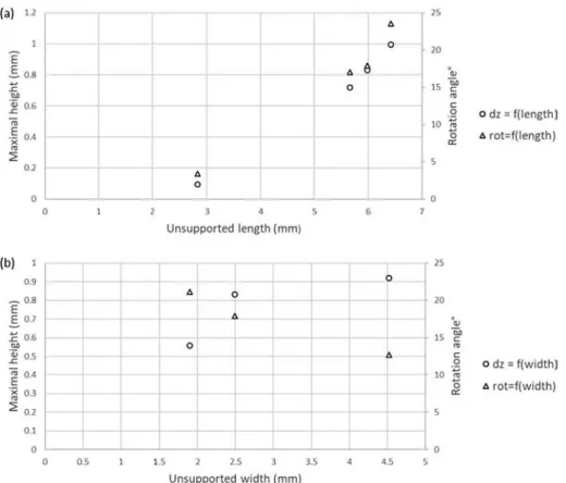
chord of the initial profile and the chord of the buckled profile. The influence of the unsupported dimensions on the tow buckles height and tow rotation during buckling is presented inFig. 6(a, b).
Fig. 6(a) shows that the maximal height and rotation of the tows increase together with the unsupported length. This is explained by the increase in the mobility of the buckling tow allowing it more room to rise and rotate. It causes a higher perceivable buckle.Fig. 6(b) shows that the increase of tow width still increases the maximal registered height whereas the rotation level decreases. Each of the transversal buckling tow is supported underneath it by a longitudinalfixed tow. As the tow buckles upward, it does so by combining two motions, i.e., deflection and rotation. During the early rotation stages of the buckle, the inner edge lifts and the outer edge has a tendency to sink until the whole tow is fully deflected. The narrower the tow, the faster the whole tow lifts completely from the supporting tow for lower bending angles. Fig. 6(a, b) also show that a higher bending angle is required to fully lift
a larger buckling tow from its supporting tow. For the same final
bending angle, wider tows have less rotation with a slight increase in height (60% rotation angle loss against 6% height increase for a 42% larger tow) as illustrated inFig. 7. Consequently, the tow buckles look smaller.
2.2.2. Effect of the tow type
In order to study the effect of tow type on the buckling, three dif-ferent reinforcements manufactured from three different tows but with similar woven structures were chosen so that to keep similar dimen-sions, i.e. sized-up flax, desized-up flax and carbon fiber all in 2 × 2 twill weaves. Each tow of the studied fabrics have different tensile, bending and torsional rigidities that are expected to influence the buckling mechanism. However it is difficult to experimentally decouple each of those rigidities. Consequently, we studied the tow type as a whole. The properties of the tows are presented inTable 2with the methods used to obtain them explained in the parameters identification Section 3.2.
During the tests, each reinforcement is loaded in tension with 300 N in load 1 and 20 N in load 2. This load is spread over 20 tows. Each reinforcement is bent in-plane up to an angle of ~40°. The tow maximal height and the tow rotation are represented respectively inFig. 8(a) and (b).Fig. 8(a) shows that the buckles elevation is higher for the carbon
tows than the other considered tows. The elevation of the buckle also begins from lower in-plane bending angles (~8°). One can also see that the sized-upflax tows exhibit higher maximal tow elevation than the desized-up ones.
A direct correlation between the increase of tow rigidities and the buckle elevation is observed. It is also possible to observe that for the three reinforcements considered, the appearance of the tow buckles happens for lower plane bending angles when the tow rigidities in-creases.
Fig. 8(b) also shows that the rotation of the buckle happens from low in-plane bending angle and the tow rotation angle is much larger for the most rigid carbon tows than the twoflax tows. In the case of the two flax tows, the tow rotation angle evolution is similar which is probably due to the relatively low difference in their rigidities. This correlates well with the observation of the maximum elevation of the tow buckle.
2.2.3. Effect of the tows tension in direction 1: fixed tow network (load 1) To study the effect of load 1 on the buckles, a series of tests has been conducted on 5 samples of 2 × 2 twill weave fabrics manufactured from sized-upflax and carbon tows respectively while imposing each time an initial load in direction 1 between 20 N and 400 N spread over 20 tows. The load in direction 2 is initially 20 N. Each sample is bent in-plane up to an angle of ~40°. The results of the test series are given inFig. 9(a) for the sized-upflax fabric and (b) for the carbon reinforcement.
As shown in bothFig. 9(a) and (b), the maximal height reached by the tow evolves oppositely to the curvature radius of the tow. The lower thefinal curvature radius (increase in the tow curvature) and the higher the tow buckles. Thefinal rotation angle, on the other hand seems to be fairly constant and independent of thefinal curvature radius. When considering the evolution of both elevation and tow rotation,Fig. 10 gives an idea on the kinematics involved during the bucking. On early bending stages, the height is mainly due to the rotation of the tow; then, as the tow continue to bend in its plane, the rotation seems to stabilize while the elevation further increases. This in turns suggests that the elevation at this point is mainly due to a global deflection of the tow that can be seen in the different tows final profiles inFig. 11. The reason behind the parabolic trend of the curvature radius (Fig. 9(a, b)) can be attributed to the combination of the in-plane bending imposed by the
Weave Material Surface density Warp density Weft density Tow unsupported length (L) Tow unsupported width (l)
Twill 2 × 2 Sized-upflax 476 g/m2 380/m 385/m 6.1 mm 2.5 mm Twill 2 × 2 Desized-upflax 465 g/m2 380/m 430/m 5.7 mm 2.4 mm Twill 2 × 2 Carbonfiber 600 g/m2 380/m 380/m 6.4 mm 2.6 mm Plain (A) Desized-upflax 262 g/m2 380/m 210/m 6.5 mm 2.1 mm Plain (B) Desized-upflax 517 g/m2 190/m 195/m 5.4 mm 4.5 mm Plain (C) Desized-upflax 458 g/m2 380/m 385/m 2.8 mm 2.6 mm
Fig. 5. Tow buckling illustration. (For interpretation of the references to color in thisfigure legend, the reader is referred to the web version of this article.) Table 1
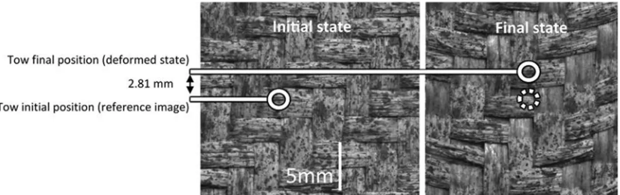
jaws alongside the tow sliding (up to 2.81 mm) as represented in Fig. 12.
During the applied in-plane bending on the device, tow sliding may
take place as shown inFig. 12and this phenomenon may have
con-sequences on thefinal curvature. The tow sliding as explained by La-banieh et al.[16]depends on the contact pressure between the warp and the weft tows. As the load 1 increases, the tow sliding is inhibited going from 2.8 mm at a load 1 of 20 N to 1.1 mm at a load 1 of 400 N for the sized-upflax. This explains the three stages presented inFig. 9(a, b), which are described further below:
– For load 1 from 20 N to 200 N: a low pressure is applied on the perpendicular tows cross-points. This allows the tows expected to buckle to slide, preventing them from achieving their potential full curvature.
– At ~200 N: an optimum is reached. The in-plane bending and tow sliding leads to the maximal possible curvature of the tows sub-mitted to in-plane bending.
– Above 200 N: the pressure applied on the cross-points combined with the friction phenomenon prevent the tow from sliding and from curving leading to a decreased curvature compared to the optimum.
Fig. 6. Evolution of the maximal height and the rotation of the buckling tow as a function of the (a) unsupported length, (b) unsupported width.
Fig. 7. Final profile of buckled tows with different unsupported widths for a bending angle of 40°. Table 2
Tows dimensional and mechanical properties with analytical and experimental critical buckling radii.
Tow origin Twill 2 × 2 sized up flax Twill 2 × 2 desized upflax Twill 2 × 2 carbon fiber Plain A desized upflax Plain C desized upflax Linear density (g/ m) 0.614 0.494 0.813 0.488 0.478 E1 (N/mm2) 19,800 7900 132,700 7820 7645 L (mm) 6.11 5.66 6.42 6.46 2.83 b (mm) 2.48 2.40 2.6 2.10 2.65 h (mm) 0.4 0.4 0.38 0.4 0.4 α 2 2 2 2 2 m 1 1 1 1 1 D11 (N·mm) 1.18 0.72 7.55 0.72 0.63 D66 (N·mm) 0.44 0.17 – 0.17 0.17 Rcr analytical (mm) 2082.9 1482.2 – 1275.7 717.7 Rcr experimental (mm) 2255 1627 – 1390 803 Δ (%) 7.63 8.90 – 8.22 10.62
When considering the influence of the increasing load 1 on the tow buckling within theflax and carbon-based fabrics, similar behavior was observed. It indicates that keeping low loads in direction 1 may delay the appearance of the buckles and reduce their height since tow sliding taking place (in a limited extent without the appearance of gaps). This sliding tend to reduce the curvature of the tow submitted to in-plane bending. These results confirm that a reduction of the blank-holder pressure as performed by Capelle et al.[18]on the tows perpendicular to the ones exhibiting the defect permits to delay the appearance of the buckles. On the other hand, when the load in direction 1 is larger than 200 N for both the fabrics, the high contact pressures prevent the tow sliding but also limits the in-plane bending of the tows. Rising the load in direction 1 to high tension values may therefore limit the curvature and consequently delay the appearance and reduce the height of the buckles. However, a risk of gaps due to tow sliding may happen, and such approach may be considered with a great care.
2.2.4. Effect of the tows tension in direction 2: tow network submitted to in-plane bending (load 2)
As for load 1, the study was done on sized-up flax with only the initial load 2 as a variable for each of the samples going from 20 N to 400 N. The results are summarized inFig. 13.
As observed with load 1, the maximal height registered evolves oppositely to the curvature radius of the tow while the rotation angle is similar for all loads. The decrease of the curvature is explained by an increase in load 2 that adds more slide to the tows and prevents them from curving or buckling. Increasing the load in direction 2 should therefore favor a reduction of the buckles size.
3. Analytical analysis
In order to be able to predict the buckling onset during the forming of a woven structure, an analytical model is set up. This approach was previously used in the literature by Beakou et al.[17]and Matveev et al.[18]in order to address the problem of tape buckling during the
automated fiber placement following a curved path. The following
work is inspired by their analytical framework.
3.1. Analytical model
Fibrous materials exhibit complex behavior; due to the possibility forfibers to slide; cross sections during bending do not necessarily
re-mains perpendicular to the neutral fiber. The Kirchhoff-Love plate
theory (and corresponding Euler-Bernoulli beam theory) are most of the time not representing well the behavior of fabrics, interlocks, and virgin fiber bundles. The bending rigidity doesn’t relate to the tension one. This is illustrated by the difference of bending behavior between a phone book with the pages glued together (tension/compression is generated) and without glue (bending of each page taken separately plus friction). In this part of the work,fibers inside a flat tow, in small strain (only the onset of buckling is considered) possess cohesion, due to the entanglement offibers and due to sizing (for desized-up flax, we assume that a small amount of sizing remains). With this assumption, we consider thatfibers don’t slide inside a tow and that Kirchhoff plate theory is valid; a link can then be made between the kinematic (the curvature) and the load (axial compression P) as illustratedFig. 14.
If the tow is considered as a thin homogenous orthotropic plate [17,18], simply supported at its outer edges and clamped on its radial edges by the neighboring tows, the differential equation for plate bending, in Eq.(1), can be solved by using the Rayleigh-Ritz approach Fig. 8. (a) Evolution of the tow maximal height during the buckling of different materials. (b) Evolution of the tow rotation during the buckling of different materials.
[20]:
∇2w=P (1)
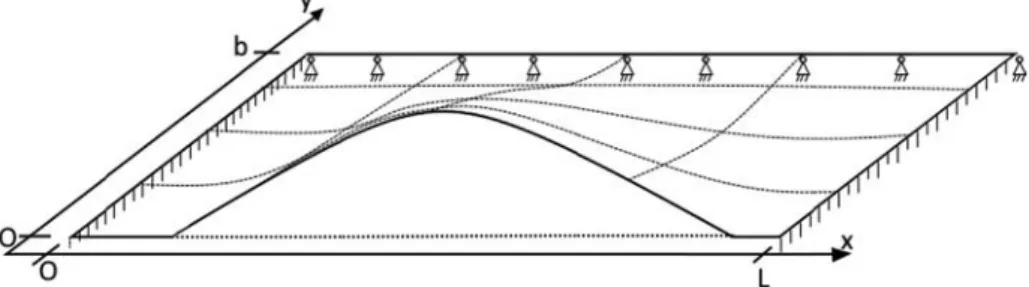
where w is the plate deflection, which, alongside its first derivative w’, are null on the clamped edges of the tow, represented inFig. 15, (w
(x = 0) = w(x = L) = 0 and w’(x = 0) = w’(x = L) = 0). The outer
edge is supposed to be simply supported and only its deflection w is null (w(y = 0) = 0). Under those assumptions, the deflection w can be de-scribed as a linear combination of the nthfirst modes and approximated,
in Eq.(2), based on the boundary conditions and the compressive load formulated previously in Eq.(1). A closed-form solution in a Rayleigh-Ritz approach can be considered:
∑
= ⎛ ⎝ − ⎞ ⎠ ⎛ ⎝ − ⎛ ⎝ ⎞⎠ ⎞ ⎠ = + w x y c y b πmx L ( , ) 1 1 cos 2 i n i i 1 1 (2) where m is the buckling mode. Only thefirst one (m = 1) will be takeninto account because it corresponds to the most critical buckling mode. P the compressive load, caused by the in-plane bending of the tow is given by Eq.(3): = ⎛ ⎝ − ⎞ ⎠ P y P αy b ( ) 0 1 (3) where P0 is the minimal buckling load applied at the inner edge, as
represented inFig. 14, of the bent plate andα is the load non-uniformity coefficient also represented in Fig. 14. The Rayleigh-Ritz approach dictates that the total energy Π, represented in Eq. (4), should be minimized by differentiating it with respect to the deflection’s ampli-tude, ci, as shown in Eq.(5):
= − w U w Q w Π( ) ( ) ( ) (4) = d dc Π 0 i (5)
where U(w) is the elastic strain energy of the plate which is defined in Eq.(6)and Q(w) is the work of the compressive load as defined in Eq. (7):
∫ ∫
⎜ ⎟ ⎜ ⎟ ⎜ ⎟ ⎜ ⎟ ⎜ ⎟ = ⎛ ⎝ ⎜ ⎛ ⎝ ⎞ ⎠ + ⎛ ⎝ ⎞ ⎠ + ⎛ ⎝ ⎞ ⎠ ⎛ ⎝ ⎞ ⎠ + ⎛ ⎝ ⎞ ⎠ ⎞ ⎠ ⎟ U w d w dx d w dy d w dx d w dy d w d dydx ( ) 1 2 D11 D22 2D12 4D66 xdy L b 0 0 2 2 2 2 2 2 2 2 2 2 2 2 (6)∫ ∫
⎜ ⎟ = ⎛ ⎝ − ⎞ ⎠ ⎛ ⎝ ⎞ ⎠ αy b d w dx dydx Q(w) 1 2P 1 L b 0 0 0 2 2 2 (7) where L is the length of the plate, b the width of the plate and Dxx are the bending stiffness of the plate. Replacing w for (n = 1) and in Eqs. Fig. 9. Evolution of the tow maximal height, rotation and curvature radius during the buckling of (a) sized-upflax tows within the fabric as a function of load 1. (b) Carbonfiber tows within the fabric as a function of load 1.Fig. 10. Evolution of tow height and tow rotation as a function of the in-plane bending angle for a sized-upflax tow under load 1 of 100 N and load 2 of 20 N.
(2),(6)and(7)and then minimizingΠ with respect to c1, the critical
buckling compressive load, Pcr is obtained as given by Eq.(8):
⎜ ⎟ = − ⎛ ⎝ + + − ⎞ ⎠ Pcr α D m π L D L b m π D b D b 1 6 24 11 2 2 90 22 160 66 40 12 2 2 4 2 2 2 2 (8)
During bending, taking into consideration small deformations and the intra-tow cohesion offibers, the edge of the tow is assumed to bend
following the curvature of a radius R at an angle θ according to
Kirchhoff’s plate theory, represented inFig. 14. The length of the inner side of the tow caused by the bending is found to be equal toθ(R-b/α) and the deformation of the tow is equal to b/(αR). The load in the inner edge, P0, generated by in-plane bending of the tow can be written
[21,22]as: = P E hb αR 1 0 (9)
In the case where the minimal Pcr (that is calculated for a re-inforcement values of L: tow unsupported length, h: tow thickness and b: unsupported tow width) is equal to P0, we are able to connect the
critical load to the geometrical bending parameters of the tow and in particular tofind the critical buckling radius Rcr as:
= − + + −
(
)
Rcr E α bh α 1(6 ) D m π L D L b m π D b D b 24 11 2 2 90 22 160 66 40 12 2 2 4 2 2 2 2 (10)Assimilating the tow to a thin orthotropic plate means that the bending (D11, D22), shear (D12, D21) and torsional (D66) stiffnesses Fig. 11. Final sized upflax tow profiles under an in-plane bending angle of ~40°.
Fig. 12. Tow Sliding during the tow in-plane bending.
that can be recovered from the laminate plate theory, where, the bending stiffness matrix for a single layer[21,22]is:
⎧ ⎨ ⎩ ⎫ ⎬ ⎭ =⎡ ⎣ ⎢ ⎤ ⎦ ⎥ ⎧ ⎨ ⎩ ⎫ ⎬ ⎭ M M M D D D D D k k k 11 12 0 21 22 0 0 0 66 x y z x y z (11)
where D11 and D22 are respectively the bending stiffness in the long-itudinal and transversal directions, representing the required torque (Mxin longitudinal and Myin transversal direction) necessary to
gen-erate a unit curvature (Kx and Ky). D11 and D22 can therefore be
considered as theflexural rigidity (Bxand By) in a direction normalized
by the perpendicular dimension (respectively width: b and length: L). = D B b 11 x (12) = D B L 22 y (13) For a dry tow with minimalistic interactions in the transverse di-rection between the constitutingfibers (mainly introduced by the false twisting during yarn manufacturing) compared to the interactions alongside thefibers in the longitudinal direction. The cohesion in the transversal direction is expected to be much smaller than in the long-itudinal direction. This results, for the bending, in Bx≫ By and with
L > b we can safely assume that D11≫ D22 and therefore, D22 can be neglected. Furthermore, to the knowledge of the authors, no
experimental procedures exists to this day to characterize the trans-versal bending behavior of a tow and this assumption can not be con-cluded upon.
D12 and D21 are equal and represent the bending coupling, which, by Poisson action effect, is the cause of an anticlastic deformation (saddle effect). Considering that the tow is fairly narrow[23]and the beveled sides of the tow[24], it is safe to assume that their effect has a negligible influence on the buckling compared to the other stiffnesses. D66, the twisting bending stiffness or torsional stiffness is the torque required to generate a twist Kz:
=
D66 G12h 6
3
(14) With G12 being the shear modulus. The critical buckling radius, Rcr, from Eq.(10)can then be written as follows:
= − + Rcr E α b hL α D L D π b m 1(6 ) (160 66 24 11 ) 3 2 2 2 2 2 (15)
This critical buckling radius is expected to correspond to the radius at which the tow buckling appears, but several parameters need to be experimentally evaluated.
3.2. Parameters identification
In order to calculate the critical buckling radius, the following
parameters E1,α, D11 and D66 need to be identified. The following
Fig. 14. Tow representation as an orthotropic plate with compressive load P representation for different values of the non-uniformity coefficient α.
sections are dedicated to the experimental identification of the para-meters.
3.2.1. Tensile modulus E1 identification
The tensile modulus E1, was determined using a tensile test on each of the considered tows. The slope of the linear part of the stress-strain curve was calculated and reported inTable 2.
3.2.2. Bending stiffness D11 identification
To identify the bending stiffness, D11, in Eq. (12), we must de-termine the bending rigidity, Bx. It is possible to do so experimentally
using the Peirce cantilever test[25]where the tow is bent under its own mass as described inFig. 14. The bending rigidity Bxcan calculated
using Eq.(16): =
( )
B L M g θ cos 8tan( ) x l θ 3 2 (16) where L is the bent length of the tow, Mlis the linear density, g is thegravity andθ is defined inFig. 16(b). This means that Eq.(12)can be written with all the parameters that are constant or measurable as shown in Eq.(16): =
( )
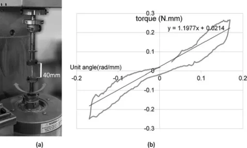
D L M g θ b 11 cos 8tan( ) l θ 3 2 (17) Following the experimental investigation, the results are presented inTable 2for four different tows taken from different woven fabrics. 3.2.3. Torsional stiffness D66 identificationTo evaluate D66 from Eq.(14), it is necessary to evaluate the in-plane shear modulus, G12, which is calculated from a torsion test that
can be performed on an ARES rheometer as shown in Fig. 17(a) and
where the torsional rigidity is given by Eq.(18) [26]: =
TL
φ G12Jt (18)
where T is the torque, L is the length of tow subjected to rotation,φ is the torsional angle, Jtis the polar moment of inertia (similar to second
moment of the area for bending) that for a rectangular surface is given by Eq.(19): ⎜ ⎜ ⎟⎟ = ⎛ ⎝ − ⎛ ⎝ − ⎞ ⎠ ⎞ ⎠ J bh h b h b 1 3 0.21 1 12 t 3 4 4 (19) T L/φ can be obtained from a torsion test by averaging the 0 to 2π and 0 to−2π slopes of the torque T as a function of the unit angle φ/L curve as represented in Fig. 17(b). The tow is subjected to an initial tensile loading up to 100 N. Finally, D66 from Eqs.(14) and (18)can be written as: = D T L h φ Jt 66 6 3 (20) The experimental results for the bending stiffness D66 are also re-ported inTable 2.
3.2.4. Non-uniformity coefficient α identification
The non-uniformity coefficient was obtained from observation on
the tow using digital image correlation using the GOM ARAMIS® soft-ware on images such as the one presented inFig. 18. Zones circled in red are areas representative of tensile loading while zones circled in blue represent compression loading areas. Both areas seem to be fairly equal. The hypothesis of pure bending can be assumed and thusα = 2 was chosen according to the representation given inFig. 16.
3.3. Calculation of the critical buckling radius
The theoretical critical radii were then calculated and compared to the experimental critical radii (tow in plane bending at which buckles appear) inTable 2. As there is no clear definition in the literature for what constitutes the threshold of the buckle’s onset, we opted to de-termine the experimental critical radii by thefirst sudden increase in the derivative of the tow elevationdzwith respect to the bending radius R (e.g. dotted line inFig. 19for plain weave C), represented inFig. 19. The aforementioned Figure should be read from highest curvature ra-dius to the lowest (right to left).
The difference between the experimental and the calculated critical radii are given inTable 2. One can observe that the differences are relatively low with an average error of 8.8%. The fact that the critical radii obtained from the experimental and the analytical approaches are close indicate that the analytical approach permits to predict with a relatively good accuracy (and a global tendency to underestimate) the critical bending radius at which the tow buckles are expected to appear. The observed differences can be due to simplification hypothesis such as the homogeneity assumption of the tow and uncertainties in the radius measurement.
As the analytical model globally permits to predict well the in-plane curvature radius at which the tow buckles are expected to appear, this method could be coupled to a simulation of the textile forming capable to predict the curvature of the tows with a good accuracy. An example of the use of such a combined approach is described in the next section of this work.
4. Modelling of the defect appearance in a macroscopic simulation Once the critical bending radius is determined experimentally or analytically, this result can be of great interest in a macroscopic si-mulation of the forming process of dry fabrics. Important effort has been paid in the past 20 years in order to predict the mechanical Fig. 16. (a) Peirce test onflax tow (b) Schematic representation of Peirce’s cantilever test.
response of fabrics during forming at macroscopic scale using numerical simulations. The reached maturity allows now to confidently predict the shear angles via the determination of yarn local orientations. It’s then straightforward to use those yarns orientation to evaluate, with a high level of confidence, the curvature of the yarns within a fabric structure during forming. Comparing the local in-plane curvature of the tow (determined during the macroscopic simulation of the textile forming) to the critical one, we can evaluate locally the risk for tow buckling to occur. Several numerical works have been completed in this direction. Gatouillat et al.[15]proposed a fully meso-scale approach using shell elements in order to predict the tow sliding defects and in [19], Iwata et al. investigated macro-scale and meso-scale numerical simulations to predict the buckling of the tows. Theyfinally proposed the use of a hybrid meso/macro-scale approach. The meso/macro-scale simulation takes advantage of macro-scale simulation to determine shear and tensions which in turn are used at meso-scale as boundary conditions in order to predict buckling and tow displacements; meso-scale simulation is only performed in areas where defect are expected to take place. Local curvature is classically evaluated in numerical Fig. 17. (a) Torsion test of ARES rheometer®. (b) Torque as a function of unit angle obtained by a torsion test.
Fig. 18. Digital image correlation of the in-plane deformations of a tow bent in its plane before appearance of tow buckling. (For interpretation of the refer-ences to color in thisfigure legend, the reader is referred to the web version of this article.)
Fig. 19. Tow elevation evolution as a function of the bending radius. (For interpretation of the references to color in thisfigure legend, the reader is referred to the web version of this article.)
(21) The main advantage of using such a framework comes from the improved continuity of the kinematic approximation that can be built in order to be C2everywhere in the domain (even at the frontier
be-tween two elements) in order to make the curvature continuous. The mechanical behavior of the fabric is taken into account considering the tensile and in-plane shear contributions of the network separately by
computing respectively the corresponding matrix, and in the
same manner as developed in[29,30]. A full description of the con-stitutive model is beyond the scope of this paper.
Tangent vectors (defied Eq.(22)) are aligned with the material directions of the elements which are chosen to be similar to thefibrous network.
∑
=∂ ∂ = ∂ ∂ = t M q ξ R ξ (i 1, 2) i i A i A A,p (22) Normal vectors are defined Eq.(23).∑
=∂ ∂ = ∂ ∂ = n M q ξ R ξ (i 1, 2) i i A i A 2 2 2 A,p 2 (23) Using and , it is possible to evaluate the curvature of each tow according to Eq.(24): = t ∧n t C || || || || i i i i 3 (24)Ciis the total curvature along the ithdirection (i = 1,2), computed
from the tangent vector and the normal vector which are both
obtained fromfirst and second derivatives of the position vector with respect to parameter coordinateξi.
In the tow buckling problem, the in-plane bending, seems from previous investigation, to have the most influence for flat tows; the bending along warp and weft directions are computed following tan-gent ant normal vectors according to first (warp) and second (weft)
directions. We define a unit vector normal to ( ) plane:
= ∧ ∧ n t t t t || || 12 1 2 1 2 (25)
The planar component of those normal vectors (associated to the in-plane curvature) is evaluated:
= −
nipl ni n12( ·n ni 12) (26)
Finally, the planar curvature Ciplalong the ithdirection is:
= t ∧ t C || n || || || i pl i ipl i 3 (27)
Fig. 20(a) shows that zones of low curvatures can be predicted on the forming simulation of a prismatic shape. The highest in-plane cur-vatures can be observed on the center and the edges of the triangular face of the prism. The curvatures detected in the red zones ofFig. 20(a) are higher than the curvature level from which tow buckles are ex-pected to appear on the threeflax and the carbon fabric tested in this work. These zones do correspond to the buckles locations observed in
Fig. 20(b) for a very different interlock fabric[13].
The zones where tow buckles are expected to appear mainly depend on the shape that induces local curvatures of the tows. However, the magnitude of the tow buckle elevation and the curvature at which the tow buckle may arrive depends on the reinforcement characteristics such as the tow geometry, the tow rigidity and the level of tension of the tows within the shape. The procedure developed in this work therefore permits to indicate according to the fabric characteristics and tension levels in the tows, the zones where tow buckles may take place. It is therefore possible to predict the appearance of tow buckles for a given reinforcement when the constituting tows are experimentally characterized.
5. Summary and conclusions
In this research work, we focus on the local buckling (at mesoscopic scale) offlat tows. Subjected to in-plane bending, a longitudinal com-pression is responsible in some configurations for a local buckling. This defect, leading to poor parts quality, was investigated experimentally and analytically.
Experimentally, a dedicated device capable of imposing tensions and an in-plane bending, combined with stereo digital image correla-tion was used to evaluate the impact of loading, the impact of the tow behavior and the impact of fabric geometry on the onset and kinematic of the buckle growth.
– We found first that an increased stiffness (in tension and in bending) tends to speedup the buckle phenomenon and to increase the high and rotation of the buckles.
– Also, fabrics with high unsupported length are more sensitive to the buckle defect (2 × 2 twill exhibits more buckles than plain weave for comparable tow width and yarn densities).
– Finally, the experimental study conclusion was that the main driving parameter for the buckling phenomenon was the curvature radius and that tensions impact the buckles through the curvature radius. Those tendencies were confirmed analytically using a Rayleigh-Ritz approach considering the unsupported portion of a tow in a fabric as an orthotropic plate subjected to bending.
– This approach successfully provide the critical curvature radius for a given fabric constituted of tows of a given nature once the me-chanical characteristics of the tows were measured together with the geometrical properties of the fabric.
Results from either the experimental or the analytical approaches can be of valuable interest in a macroscopic simulation of the forming process of a dry fabric. Critical curvature radius can be compared to a simulated one in order to predict the likelihood and location of local buckling defects in a complex part.
– We chose to illustrate this result using an Isogeometrical framework among others for its capability to capture naturally the curvature. – No additional development is needed and only a post processing is
required to gather information regarding the buckle onset in a forming process.
This approach is, of course, very simplified since no tow sliding can be taken into account because of the Lagrange description used for the kinematic. Nevertheless, in classical fabric forming, the sliding defect corresponds to quite extreme scenarios and obtaining a tow buckling criterion in a simulation represents a real gain at low cost. Of course, when tensions in the tows reach certain levels and that tow sliding occurs, meso-scale[11]or smarter multi-scale approaches[19]should be favored.
.
simulations using neighboring elements [6,27] in order to take into account the bending behavior during a fabric forming. This behavior is proven to be highly influent on the wrinkle’s shapes and sizes.
Meso-scale and meso/macro-scale, while being accurate in the prediction of the defect, still require intensive computation resources. Thus, in this work, the use of a macro-scale simulation within an iso-geometrical framework [28] is proposed.
Considering a set of rational degree p NURBS shape functions RA,p.
Let us denote = 8 (ξ1,ξ2,ξ3), the coordinates in the 3 dimensional parametric space of a considered point; its position vector at a given time t can be obtained considering the control points positions and the value of the NURBS shape functions at as shown in Eq. (21).
References
[1] Greb C, Lenz C, Lengersdorf M, Gries T. Fabrics for reinforcement of engineering composites. Eng high-performance text 2018;vol. c:489–512.https://doi.org/10. 1016/B978-0-08-101273-4.00019-6.
[2] Potter K, Khan B, Wisnom M, Bell T, Stevens J. Variability,fibre waviness and misalignment in the determination of the properties of composite materials and structures. Compos Part A Appl Sci Manuf 2008;39:1343–54.https://doi.org/10. 1016/j.compositesa.2008.04.016.
[3] Lightfoot JS, Wisnom MR, Potter K. Defects in woven preforms: formation me-chanisms and the effects of laminate design and layup protocol. Compos Part A Appl Sci Manuf 2013;51:99–107.https://doi.org/10.1016/J.COMPOSITESA.2013.04. 004.
[4] Nosrat Nezami F, Gereke T, Cherif C. Analyses of interaction mechanisms during forming of multilayer carbon woven fabrics for composite applications. Compos Part A Appl Sci Manuf 2016;84:406–16.https://doi.org/10.1016/J.COMPOSITESA. 2016.02.023.
[5] Rashidi A, Milani AS. Passive control of wrinkles in woven fabric preforms using a geometrical modification of blank holders. Compos Part A Appl Sci Manuf 2018;105:300–9.https://doi.org/10.1016/J.COMPOSITESA.2017.11.023. [6] Boisse P, Hamila N, Vidal-Sallé E, Dumont F. Simulation of wrinkling during textile
composite reinforcement forming. Influence of tensile, in-plane shear and bending stiffnesses. Compos Sci Technol 2011;71.https://doi.org/10.1016/j.compscitech. 2011.01.011.
[7] Hosseini A, Kashani MH, Sassani F, Milani AS, Ko FK. Identifying the distinct shear wrinkling behavior of woven composite preforms under bias extension and picture frame tests. Compos Struct 2018;185:764–73.https://doi.org/10.1016/J. COMPSTRUCT.2017.11.033.
[8] Hübner M, Rocher JE, Allaoui S, Hivet G, Gereke T, Cherif C. Simulation-based investigations on the drape behavior of 3D woven fabrics made of commingled yarns. Int J Mater Form 2016;9:591–9. https://doi.org/10.1007/s12289-015-1245-8.
[9] Allaoui S, Hivet G, Soulat D, Wendling A, Ouagne P, Chatel S. Experimental pforming of highly double curved shapes with a case corner using an interlock re-inforcement. Int J Mater Form 2014;7:155–65. https://doi.org/10.1007/s12289-012-1116-5.
[10] Ouagne P, Soulat D, Moothoo J, Capelle E, Gueret S. Complex shape forming of a flax woven fabric; analysis of the tow buckling and misalignment defect. J Compos Mater 2013;51A:1–10.https://doi.org/10.1016/j.compositesa.2010.08.011. [11] Gatouillat S, Bareggi A, Vidal-Sallé E, Boisse P. Meso modelling for composite
preform shaping - simulation of the loss of cohesion of the wovenfibre network. Compos Part A 2013;54:135–44.https://doi.org/10.1016/j.compositesa.2013.07. 010.
[12] Labanieh AR, Garnier C, Ouagne P, Dalverny O, Soulat D. Intra-ply yarn sliding defect in hemisphere preforming of a woven preform. Compos Part A Appl Sci Manuf 2018;107:432–46.https://doi.org/10.1016/J.COMPOSITESA.2018.01.018. [13] Ouagne P, Soulat D, Hivet G, Allaoui S, Duriatti D. Analysis of defects during the
preforming of a wovenflax reinforcement. Adv Compos Lett 2011;20:105–8. [14] Capelle E, Ouagne P, Soulat D, Duriatti D. Complex shape forming offlax woven
fabrics: design of specific blank-holder shapes to prevent defects. Compos Part B Eng 2014;62:29–36.https://doi.org/10.1016/j.compositesb.2014.02.007. [15] Tephany C, Gillibert J, Ouagne P, Hivet G, Allaoui S, Soulat D. Development of an
experimental bench to reproduce the tow buckling defect appearing during the complex shape forming of structuralflax based woven composite reinforcements. Compos Part A Appl Sci Manuf 2016;81:22–33.https://doi.org/10.1016/j. compositesa.2015.10.011.
[16] Ouagne P, Soulat D, Tephany C, Gillibert J. Measurement of the appearance and growth of tow buckling defect in the frame of complex shape manufacturing process by using fringe projection technique. Strain 2016;52:559–69.https://doi.org/10. 1111/str.12206.
[17] Beakou A, Cano M, Le Cam JB, Verney V. Modelling slit tape buckling during au-tomated prepreg manufacturing: a local approach. Compos Struct
2011;93:2628–35.https://doi.org/10.1016/j.compstruct.2011.04.030.
[18] Matveev MY, Schubel PJ, Long AC, Jones IA. Understanding the buckling behaviour of steered tows in Automated Dry Fibre Placement (ADFP). Compos Part A Appl Sci Manuf 2016;90:451–6.https://doi.org/10.1016/j.compositesa.2016.08.014. [19] Iwata A, Inoue T, Naouar N, Boisse P, Lomov SV. Coupled meso-macro simulation of
woven fabric local deformation during draping. Compos Part A Appl Sci Manuf 2019;118:267–80.https://doi.org/10.1016/J.COMPOSITESA.2019.01.004. [20] Wu Z, Weaver PM, Raju G, Chul Kim B. Buckling analysis and optimisation of
variable angle tow composite plates. Thin-Walled Struct 2012;60:163–72.https:// doi.org/10.1016/J.TWS.2012.07.008.
[21] Kubiak T. Static and dynamic buckling of thin-walled plate structures; 2013, p. 27–47.https://doi.org/10.1007/978-3-319-00654-3.
[22] Balcioǧlu HE, Aktaş M. An investigation on lateral buckling of laminated compo-sites with delamination. Indian J Eng Mater Sci 2013;20:367–75.
[23] Swanson SR. Anticlastic effects and the transition from narrow to wide behavior in orthotropic beams. Compos Struct 2001;53:449–55.https://doi.org/10.1016/ S0263-8223(01)00055-1.
[24] Conway HD, Farnham KA. Anticlastic curvature of strips of variable thickness. Int J Mech Sci 1965;7:451–8.https://doi.org/10.1016/0020-7403(65)90047-0. [25] Peirce FT, Peirce FT. The“Handle” of cloth as measurable quantity. J Text Inst
Trans 1964;55:516–30.https://doi.org/10.1080/19447015508664900. [26] Roark RJ, Young WC, Plunkett R. Formulas for Stress and Strain, vol. 43; 1976.
https://doi.org/10.1115/1.3423917.
[27] Mathieu S, Hamila N, Bouillon F, Boisse P. Enhanced modeling of 3D composite preform deformations taking into account localfiber bending stiffness. Compos Sci Technol 2015;117:322–33.https://doi.org/10.1016/J.COMPSCITECH.2015.07. 005.
[28] Hughes TJR, Cottrell JA, Bazilevs Y. Isogeometric analysis: CAD,finite elements, NURBS, exact geometry and mesh refinement. Comput Meth Appl Mech Eng 2005;194:4135–95.https://doi.org/10.1016/J.CMA.2004.10.008.
[29] De Luycker E, Morestin F, Boisse P, Marsal D. Simulation of 3D interlock composite preforming. Compos Struct 2009;88:615–23.https://doi.org/10.1016/j. compstruct.2008.06.005.
[30] Hamila N, Boisse P. Simulations of textile composite reinforcement draping using a new semi-discrete three nodefinite element. Compos Part B Eng
2008;39:999–1010.https://doi.org/10.1016/J.COMPOSITESB.2007.11.008.
Fig. 20. (a) In-plane curvature radii along x (left) and y (right)fiber networks directions (logscale) during a prismatic fabric forming. (b) Location of buckles during the deep drawing of a carbon interlock fabric on a prismatic shape[13]the initial direction of the fabric is aligned along the edges. (For interpretation of the references to color in thisfigure legend, the reader is referred to the web version of this article.)