To cite this version :
Nishikawara, Masahito and Nagano, Hosei and Prat,
Marc
Numerama study on heat-transfer characteristics of loop heat pipe
evaporator using three-dimensional pore network model. (2017) Applied
Thermal Engineering, vol. 126. pp. 1098-1106. ISSN 1359-4311
O
pen
A
rchive
T
OULOUSE
A
rchive
O
uverte (
OATAO
)
OATAO is an open access repository that collects the work of Toulouse researchers and
makes it freely available over the web where possible.
This is an author-deposited version published in :
http://oatao.univ-toulouse.fr/
Eprints ID : 19956
To link to this article: DOI: 10.1016/j.applthermaleng.2017.02.050
URL : http://dx.doi.org/10.1016/j.applthermaleng.2017.02.050
Any correspondence concerning this service should be sent to the repository
administrator:
[email protected]
Research Paper
Numerical study on heat-transfer characteristics of loop heat pipe
evaporator using three-dimensional pore network model
Masahito Nishikawara
a,⇑, Hosei Nagano
b, Marc Prat
caDepartment of Mechanical Engineering, Toyohashi University of Technology, 1-1 Hibarigaoka, Tenpaku-cho, Toyohashi, Aichi 441-8580, Japan bDepartment of Aerospace Engineering, Nagoya University, Japan
cUniversité de Toulouse, INPT, UPS, IMFT, Toulouse, France
a b s t r a c t
An important consideration while designing the shape of a capillary evaporator is the phase distribution in the wick. However, the distribution depends on the working fluids and porous materials. This study investigates the heat-transfer characteristics of a loop heat pipe (LHP) evaporator by using a three-dimensional pore network model with a dispersed pore size wick. The simulation considers saturated and unsaturated wicks. A stainless steel (SS)-ammonia, polytetrafluoroethylene (PTFE)-ammonia, and copper-water LHP are simulated. The copper-water LHP has the highest transition heat flux to the unsat-urated wick. When the optimum evaporator shape of the copper-water LHP is designed, it is reasonable to assume that the phase state is saturated. On the other hand, for the ammonia LHP design, the state is assumed to be unsaturated. Simulation results show the heat-transfer structure in the evaporator and indicate that the applied heat flux concentrates on the three-phase contact line (TPCL) within the case, wick, and grooves. An evaporator configuration with circumferential and axial grooves is simulated to investigate the effect of the TPCL length. Results indicate that the optimum shape can be realized by vary-ing the TPCL length. The proposed method is expected to serve as a simple approach to design an evaporator.
1. Introduction
Loop heat pipes (LHPs) and capillary pumped loops are widely used to achieve thermal control in various applications such as spacecraft, automobiles, computers, LED-based devices, and power semiconductor devices. The thermal resistance of an LHP is the sum of the thermal resistances of the evaporator and condenser. The evaporator thermal resistance is based on two-phase flow in a porous structure with a phase change. There have been many reports on two-dimensional evaporator simulations [1–4], and recently, a more accurate three-dimensional model was developed
[5–12]. Depending on the heat flux applied to the evaporator, the wick phase state is divided into a saturated state with a liquid phase and an unsaturated state with liquid and vapor phases, as shown inFig. 1. Chernysheva and Maydanik[5,6]determined the shape of the liquid–vapor interface based on the local temperature of the wick but ignored the evaporation at the liquid–vapor
interface in the wick. On the other hand, other studies[1–4,8,9]
were based on the maximum capillary pressure and considered the evaporation within the wick. In a copper-water LHP[5,6], an unsaturated state was not formed at less than 100 W/cm2.
How-ever, in an ammonia LHP[8], an unsaturated state was formed at more than 1 W/cm2. The threshold of the transition heat flux is
dif-ferent because it depends on the working fluid and wick thermal conductivity.Table 1lists the transition heat flux for an unsatu-rated wick in different studies. Among the cited studies, only Refs.
[2,13] present experimental results; the others present results based on numerical simulations. In the simulations, the condition for transition to an unsaturated state is given by
T ! Tsat"
D
Tsup>D
Tnuc ð1Þwhere T is the wick temperature, Tsatis the saturation temperature,
DTsupis the superheat of the wick, and DTnucis the threshold of
nucleation. The nucleation superheat is considered to be a constant in some studies, whereas it is calculated in others. For example, in Refs.[3,8], the nucleation superheat is considered as 4 !C. However, because nucleation superheat depends on the working fluid and ⇑ Corresponding author.
nucleus state, its estimation is difficult. Therefore, to obtain an optimum design for the evaporator shape, the thermal characteris-tics of the saturated state are important in some cases whereas those of the unsaturated state are important in others, depending on the working fluid and the configuration of the evaporator. In this study, a numerical model of an LHP evaporator was developed using
a pore network model; then, the transition heat flux in some evap-orator configurations and the heat-transfer structure in both states of the wick were investigated.
Vapor Interface Liquid v
P
lP
cap_maxP
Bulk Throat PoreFig. 2. Sketch of pore network and liquid-vapor interface balance.
0.0 0.2 0.4 0.6 0.8 1.0 1.2 0.0 0.5 1.0 1.5 2.0 2.5
V
o
lu
m
e f
ra
ct
io
n
Pore radius (μm)
Sim. Meas.Fig. 3. Pore radius distribution used in the simulation. Simulation value is used in throat radius rth. Measurement value is obtained by mercury intrusion method.
Nomenclature A area (m2)
DPint pressure difference at liquid–vapor interface (Pa)
DTsup superheat of liquid phase (K)
DTnuc boiling incipient superheat (K)
hc convective heat-transfer coefficient (W/m2%K)
hevap evaporator heat-transfer coefficient (W/m2%K)
hi interfacial heat-transfer coefficient (W/m2%K)
Hfg latent heat (J/kg)
keff effective thermal conductivity (W/m%K)
keff_l effective thermal conductivity of liquid phase (W/m%K)
keff_v effective thermal conductivity of vapor phase (W/m%K)
_
mn mass flow rate for normal direction (kg/s)
n normal direction (m)
P pressure (Pa)
Pcap_max maximum capillary pressure (Pa)
Pgr groove pressure (Pa)
_qapply applied heat flux (W/m2)
r bubble radius (m) rth throat radius (m)
T temperature (K)
Te_max the maximum temperature the case (K)
Tgr groove temperature (K)
Tsat saturation temperature (K)
r
surface tension (N/m)q
_v vapor density (kg/m3)h contact angle (rad)
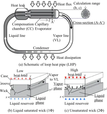
Liquid line Vapor line (VL) Capillary Evaporator Condenser A Cross-section (A-A’) Heat flux Heat dissipation A’ Heat leak Compensation chamber (CC) Calculation range (b, c)
z
(a) Schematic of loop heat pipe (LHP)
x z y Case Wick Groove Liquid phase Liquid reservoir Low
heat load Vapor to VL
(b) Liquid saturated wick (1Φ)
x z y Vapor phase Liquid phase Liquid reservoir High heat load (c) Unsaturated wick (2Φ) Γ Γ
Fig. 1. Behavior of phase distribution in LHP wick. Cis evaporation interface. Capillary pressure is developed atC.
Table 1
Transition heat flux for unsaturated wick in different studies. Exp. indicates experimental results.
Study Working fluid Wick bulk thermal conductivity, W/m%K Pore radius,lm Transition heat flux, W/cm2
Figus et al.[1] Ammonia 0.4, 10, 0.5 10 <0.45
Kaya and Goldak[3] Ammonia 14.5 1.2 0.1254–0.3762
Wan et al.[4] Ammonia 15.2, 90.4 – <4
Mottet et al.[8] Ammonia 4.18 1 1
Zhao and Liao[2](Exp.) Water 0.78 256 17.72
Chernysheva and Maydanik[6] Water That of copper 21 100–111
Hatakenaka et al.[13](Exp.) Water That of stainless steel 2.8 <1.69
Mottet et al.[8] FC3284 46 550 0.5
2. Numerical model
Here, a three-dimensional mathematical model using a pore network is presented. Sketch of the lattice pore network is shown inFig. 2. The network consists of pores and throats. This pore net-work model can consider the pore radius distribution in the wick. The radius distribution used in the model is shown inFig. 3and is generated based on measurement results obtained by the mercury intrusion method. The model details are described in Refs.[9–12].
Fig. 4shows the flowchart for the numerical solution process. First, the thermal-hydraulics states of a liquid saturated wick (1U) are solved. Here, system of equations of pressure based on pore net-work and energy conservation including convection term are solved. Then, temperature, pressure and liquid velocity are obtained. If the superheat of the liquid phase at the contact surface between the wick and case exceeds the nucleation superheat, the
phase state becomes unsaturated. Transition from a saturated state to an unsaturated state is determined as follows:
D
Tsup>D
Tnuc¼2
r
Tsatq
vrHfgð2Þ
whereDTsupis the superheat of the liquid phase in the wick,DTnucis
the boiling incipient superheat,
r
is the surface tension, Tsatis thesaturation temperature,
q
_v is the density of the vapor, r is theradius of the bubbles, and Hfgis the latent heat. In this model, r is
the mode pore radius of the wick and is 1.2
l
m fromFig. 3. After vapor nucleation occurs, a vapor phase forms at the contact surfaceYes
No
1. Begin 1Φ calculation
3. Calculate the liquid-vapor interface
Start
5. Pressure balance achieved
at the interface?
End
4. Begin 2Φ calculation.
2. Nucleation superheat achieved?
Yes
No
Fig. 4. Flowchart of numerical solution process.
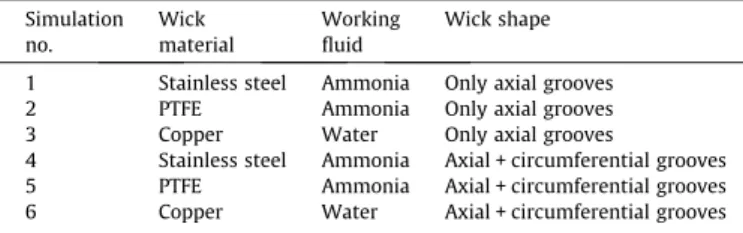
Table 2
Configuration of evaporator used in simulations.
Simulation no. Wick material Working fluid Wick shape
1 Stainless steel Ammonia Only axial grooves 2 PTFE Ammonia Only axial grooves 3 Copper Water Only axial grooves
4 Stainless steel Ammonia Axial + circumferential grooves 5 PTFE Ammonia Axial + circumferential grooves 6 Copper Water Axial + circumferential grooves
Table 3
Transition heat flux for unsaturated wick in different evaporator configurations. Evaporator configuration Transition heat flux, W/cm2 Stainless steel-ammonia 1.25 PTFE-ammonia <0.3125 Copper-water 4.375 0 1,000 2,000 3,000 4,000 5,000 6,000 7,000 0 5 10 15 20
H
ea
t-tr
an
sf
er
c
o
ef
fi
ci
en
t,
h
ev a p(W
/m
2K
)
H
ea
t-tr
an
sf
er
c
o
ef
fi
ci
en
t,
h
ev a p(W
/m
2K
)
Heat flux (W/cm
2)
2ΦStainless steel - ammonia
PTFE - ammonia 2Φ 0 5,000 10,000 15,000 20,000 25,000 30,000 35,000 0 5 10 15 20
Heat flux (W/cm
2)
2Φ Copper - water Vapor penetration(a) Copper-water LHP
(b) Stainless steel-ammonia and
PTFE-ammonia LHPs
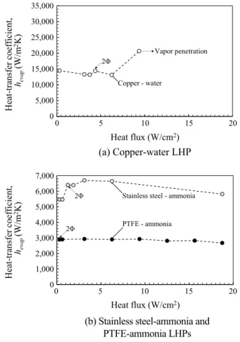
Fig. 6. Evaporator heat-transfer coefficient as function of heat flux.
0 20 40 60 80 100 -50 0 50 100 150
Δ
T
n u c(°
C
)
Saturation temperature (°C)
R134a Ethanol Acetone Water Ammonia PropyleneFig. 5. Boiling incipient superheat for each working fluid (r = 1.2lm).
Please cite this article in press as: M. Nishikawara et al., Numerical study on heat-transfer characteristics of loop heat pipe evaporator using three-dimen-sional pore network model, Appl. Therm. Eng. (2017),http://dx.doi.org/10.1016/j.applthermaleng.2017.02.050
between the wick and case until the vapor contacts the grooves. Next, the thermal-hydraulics states of an unsaturated wick (2U) are solved. When the pressure difference between the vapor and liquid phases at the interface in the wick,DPint, exceeds the
maxi-mum capillary pressure in the pore throat, the vapor phase dis-places the liquid phase, as expressed in Eq.(3):
D
Pint> Pcap max¼2
r
cos h rthð3Þ
where Pcap_maxis the maximum capillary pressure, h is the contact
angle, and rthis cylinder radius of the throat as shown in Fig. 2.
The calculation is iterated until all the interfaces satisfy Eq.(3). In the saturated wick, liquid evaporates on the groove-wick interface, and in the saturated wick, liquid evaporates within the wick and on the groove-wick liquid-vapor interface.
3. Results and discussion for classical evaporator shape The numerical model was validated by comparing its results with the experimental results obtained using a
polytetrafluo-roethylene (PTFE)-ethanol LHP[9]. Wettability of PTFE is generally hydrophobic, however in some fluid combinations with ammonia, ethanol, etc., the wettability is hydrophilic. The contact angle
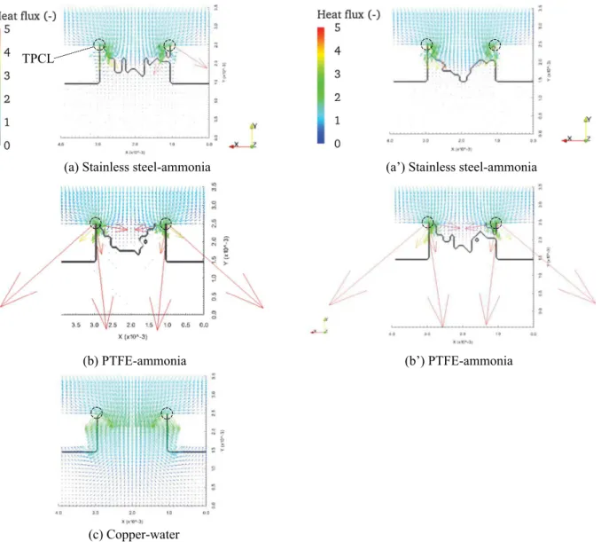
(b) PTFE-ammonia
(a) Stainless steel-ammonia
TPCL
(c) Copper-water
(b’) PTFE-ammonia
(a’) Stainless steel-ammonia
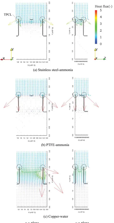
Fig. 7. Distribution of heat flux vectors and liquid–vapor interface shape on the x-y plane. The color bar is normalized with an applied heat flux. The applied heat fluxes are 6.25 W/cm2
in (a, b, c) and 12.5 W/cm2
in (a0, b0). Only axial grooves are created. The TPCL length is 500 m!1. No data in (c0) due to vapor penetration. (For interpretation of the references to color in this figure legend, the reader is referred to the web version of this article.)
x
z
y
Case Wick Axial groove Liquid phase Liquid reservoir Heat load Vapor phase Contact surface, AcontLz_g Lx_g/2 Circumferential groove y-z plane x-y plane
between PTFE and ethanol was 30!, which was measured by using a contact angle meter (KYOWA DM-301). The dimensions of the evaporator mentioned in this section are similar to the dimen-sions considered in the validation. The simulation is performed by changing the bulk thermal conductivities of the wick and working fluid.Table 2 lists the configurations of the evaporator used in the simulations. The results of simulations 1, 2, and 3 are presented in this section. Those of simulations 4 and 5 are pre-sented in the next section. Fluid properties are calculated using REFPROP[14], and temperature dependence is taken into account. The porous characteristics are the same in all the wicks. The bulk thermal conductivity of stainless steel (SS), PTFE, and copper are 16, 0.25, and 386 W/m%K, respectively. The contact angle is 0! under all conditions. The saturation temperature of the compen-sation chamber (CC) is 29.4 !C. The groove saturation temperature is calculated from the pressure loss through the vapor line, con-denser, and liquid line.
The heat flux applied to the evaporator is varied from 0.3125 W/ cm2to the maximum heat flux of vapor penetration into the CC.
The transition heat fluxes to the unsaturated wick, which satisfy Eq.(2), are listed inTable 3. The transition heat flux of the PTFE wick is the lowest. The simulation could not run at less than 0.3125 W/cm2. The reason for the low transition heat flux of the
PTFE wick is that the temperature distribution at the contact sur-face between the wick and case is large owing to its low thermal conductivity. The transition heat fluxes using water as the working fluid vary from 1.7 to 100 W/cm2, as seen in the previous studies
listed inTable 1. Results of this simulation is in this range as shown inTable 3. The relationship of the transition heat flux with the
wick thermal conductivity and pore radius cannot be found. The presence of non-condensation gas, surface roughness of the evaporator case, and condition of contact between the case and wick may affect the transition heat flux critically. The prediction of the transition heat flux seems to be complicated. Therefore, in the future, measurements should be performed to investigate vapor nucleation in a porous medium.
The boiling incipient superheat,DTnucin Eq.(2), is calculated for
the working fluid used in LHPs. The temperature dependence of fluid properties is taken into account. The nucleus radius is 1.2
l
m. The results are presented inFig. 5. Water shows the high-estDTnucvalue among all the fluids considered. Fluids that are athigh pressure at room temperature, such as ammonia, have low boiling incipient superheat values; therefore, they are subject to transitions to the unsaturated state at low heat flux.
Fig. 6presents the evaporator heat-transfer coefficient for each evaporator configuration. The evaporator heat-transfer coefficient is calculated as
hevap¼ _qapply=ðTe max! TsatÞ ð4Þ
where Te_maxis the maximum temperature of the case and Tsatis the
groove saturation temperature. In the copper-water LHP, vapor penetration occurs at 12.5 W/cm2. The pressure loss through the
vapor line, condenser, and liquid line is 76 kPa against a capillary pressure of 100 kPa at the maximum heat flux. Hence, the pressure loss of the transport line is dominant. Because water has a high transition heat flux, the heat flux at the capillary limit can be com-parable to the transition heat flux for the unsaturated state. There-fore, during the design of the optimum evaporator shape of the copper-water LHP, it is reasonable to assume that the phase state is saturated with liquid.
The evaporator heat-transfer coefficient of the ammonia LHP reaches a local maximum in the unsaturated state and decreases with an increase in the heat flux. Such heat-transfer characteristics have been measured in some LHP experiments [15–17]. These characteristics can be explained as follows. When the wick is unsaturated, due to increasing liquid-vapor interface area, the heat-transfer coefficient increases with increasing the heat. While, due to an increasing vapor phase in the wick, the heat-transfer coefficient also decreases with increasing the heat. This is because the liquid-vapor interface is far from the heating surface. Due to above two reasons, the heat-transfer coefficient for the unsatu-rated wick has a local maximum characteristic as shown inFig. 6
(b). The local maximum characteristics of the evaporator heat-transfer coefficient is discussed in detail in Refs. [8,21]. Because the transition heat flux is much lower than the heat flux at the cap-illary limit, it is reasonable to assume that the phase state is that of an unsaturated wick with vapor and liquid when designing the optimum evaporator shape of an ammonia LHP.
The heat-transfer coefficient of the copper-water LHP is several times higher than those of the other two LHPs. Jump characteristics are found inFig. 6(a). Because the evaporator heat-transfer coeffi-cient is dominated by thermal conduction from the heating surface to liquid-vapor interface in or on the wick, a higher thermal con-ductive wick benefits more from the effect of the interface area increasing. On comparison between the copper-water and SS-ammonia LHPs, bulk thermal conductivity of copper and SS are 16 W/m%K and 400 W/m%K, therefore the difference is 25 times. It is considered that such a large difference directory affects the jump of the evaporator heat-transfer coefficient from a saturated to an unsaturated state.
To analyze the heat flow structure in the evaporator, the heat flux vector is calculated as
_q("!keff
r
T ! _qapply ð5Þ 0 5,000 10,000 15,000 20,000 25,000 30,000 35,000 0 5 10 15 20H
ea
t-tr
an
sf
er
c
o
ef
fi
ci
en
t,
h
ev a p(W
/m
2K
)
H
ea
t-tr
an
sf
er
c
o
ef
fi
ci
en
t,
h
ev a p(W
/m
2K
)
Heat flux (W/cm
2)
2Φ Copper - water Vapor penetration 0 1,000 2,000 3,000 4,000 5,000 6,000 7,000 0 5 10 15 20Heat flux (W/cm
2)
2Φ Stainless steel - ammonia
2Φ PTFE - ammonia
(a) Copper-water LHP
(b) Stainless steel-ammonia and
PTFE-ammonia LHPs
Fig. 9. Evaporator heat-transfer coefficient as function of heat flux. Circumferential and axial grooves are created. The TPCL length is 640 m!1
where keff is the effective thermal conductivity of the wick. The
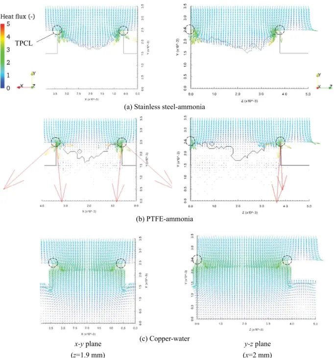
analysis results are presented in Fig. 7. Fig. 7 also presents the liquid-vapor interface. In terms of phase distribution, the SS-ammonia and PTFE-SS-ammonia LHPs show the vapor phase at the center of the wick. On the other hand, the vapor phase for the copper-water LHP appears on a section of the three-phase contact line (TPCL) within the case, wick, and grooves and does not exist at the center of the wick. This is becauseDTnucof water is much
higher. The difference of the phase distribution leads to the partic-ular characteristics of the heat-transfer coefficient for the copper-water evaporator.
The heat applied from the top of the case concentrates at the TPCL within the case, wick, and grooves as the high flux is shown in red arrows, and then transfers to the grooves by evaporation. The difference in the distribution of the heat flow depends on the
thermal conductivity of the wick and maximum heat fluxes at the TPCL, which are 5.68, 17.5, and 2.88 in the SS-ammonia, PTFE-ammonia, and copper-water LHPs, respectively. The heat flux at the bottom of the PTFE wick is low, so the heat leak to the CC is the lowest for this case. In this paper, the discussion is focused on only the evaporator, but when the performance of an LHP system is considered, the amount of the heat leak should be included in the discussion.
Because the heat flux concentrates at the TPCL in any phase state, it is considered that the evaporator heat-transfer coefficient can be enhanced by making the TPCL longer. This simulation is presented in the next section. A TPCL length of 500 m!1 is
considered in the present section. Note that the TPCL length is represented as the area density of the heat-load area; therefore, the unit is m!1.
(b) PTFE-ammonia
(a) Stainless steel-ammonia
(c) Copper-water
x-y plane
(z=1.9 mm)
y-z plane
(x=2 mm)
TPCL
Fig. 10. Distribution of heat flux vectors and liquid–vapor interface shape on x-y and y-z plane. The color bar is normalized with an applied heat flux. The applied heat flux is 6.25 W/cm2
. Both axial and circumferential grooves are created. The TPCL length is 640 m!1 .
4. Three-dimensional groove shape
4.1. Calculation domain and boundary conditions
The computational domain is depicted inFig. 8. Circumferential grooves as well as axial grooves are created to make the TPCL longer. The circumferential groove approach has been proposed in Refs. [18,19], and the improvement of the evaporator heat-transfer coefficient has been verified experimentally. To compare the axial groove configurations only, the area of the contact surface between the case and wick is maintained to be the same (0.5) in the ratio of this area to the area of the heat load. In the case of a cylindrical evaporator, the axial length is longer, so the TPCL can be made longer by increasing the number of circumferential grooves. In this simulation, the width of the axial groove is equal to that of the circumferential groove. For this shape, the contact surface is square and the TPCL length is 640 m!1.
The boundary conditions are explained as follows. A spatial periodic boundary is imposed at z = 0, Lz, except on the upper side of the wick. At the wick–groove interface with z = 0, Lz-Lz_g, when the wick phase is saturated, the boundary conditions are given by !keff l@T @n ! ! ! ! C ¼ hiðT ! TgrÞ and ð6Þ _ mn¼ hiAðT ! TgrÞ Hfg ð7Þ
and when the wick phase is unsaturated, they are given by
!keffv @T @n ! ! ! ! C ¼ hcðT ! TgrÞ and ð8Þ P ¼ Pgr ð9Þ
where hi is the interfacial heat-transfer coefficient [20]. These
boundary conditions are the same as the conditions at the wick– groove interface in the x direction. The other boundary conditions are the same as those described in the previous section.
4.2. Results and discussion
Fig. 9 presents the results of the evaporator heat-transfer coefficient as a function of the heat flux. Fig. 10 presents the distribution of the heat flux vectors defined in Eq.(5)on the x-y and y-z planes. The maximum heat-transfer coefficient for the SS-ammonia LHP is 6600 W/m2%K, which is higher than that for
the LHP with only axial grooves (6100 W/m2
%K). The maximum heat flux at the TPCL for the SS-ammonia LHP is 3.96, which is smaller than that for the LHP with only axial grooves. The evapora-tor heat-transfer coefficient for the copper-water LHP does not increase. The maximum heat flux is 2.63, which is smaller than that for the LHP with only axial grooves. The reason why the evaporator heat-transfer coefficient of the copper-water LHP did not increase may be related to the increasing of the liquid-vapor interface area on the unsaturated wick against the saturated wick. When the TPCL length is 640/m (Fig. 10), the increasing of the liquid-vapor interface area on the unsaturated wick is 1.0004, which is the ratio to the interface area of the satu-rated wick. While, the increasing liquid-vapor interface area with 500/m (Fig. 7) is 1.1. Benefit of the increasing liquid-vapor inter-face area may be more dominant than the benefit of the increasing of the TPCL length.
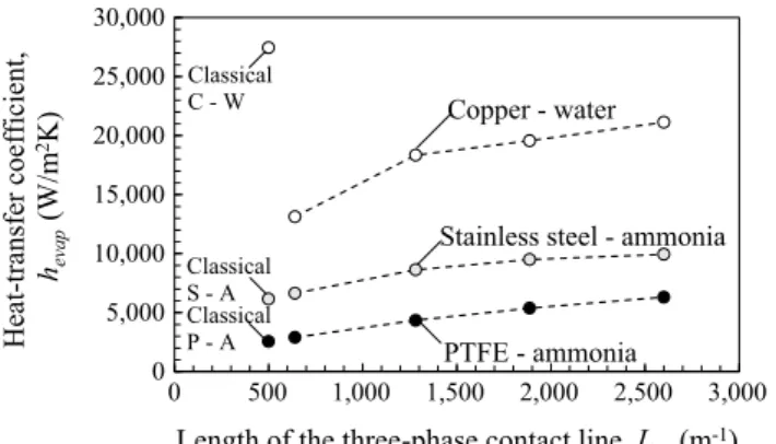
Fig. 11presents the evaporator heat-transfer coefficient of each configuration as a function of the TPCL length. The length is divided by the area of the heat load. The TPCL length changes with the width and number of both the axial and circumferential grooves. The area of the contact surface between the case and wick is con-stant (0.5). All the phase states of the wick shown inFig. 11are unsaturated. The results for the classical wick shape with 500 m!1 TPCL length were also presented in Fig. 11. The
heat-transfer coefficient increases with an increase in the TPCL length in any configuration except the classical copper-water LHP. The maximum heat-transfer coefficient for the SS-ammonia LHP is 9900 W/m2%K when the TPCL length is 2600 m!1, and both the
groove widths are 0.3 mm. It is found that the evaporator heat-transfer coefficient can be enhanced by making the TPCL longer. However, when the TPCL is very long, because the groove width is very small, the effect of the distribution of saturation pressure in the grooves cannot be neglected. Therefore, it is considered that the optimum shape of the LHP evaporator can be designed by establishing a trade-off between an increase in the heat-transfer coefficient achieved by increasing the TPCL length and the effect of increasing pressure loss in the grooves. The proposed method for optimization of wick shape is presented in Ref.[22]. In addition, a detailed heat-transfer simulation at the TPCL should be per-formed in the future.
Fig. 12presents the distribution of the heat flux vectors on the x-y and y-z planes when the TPCL length is 2600 m!1. For
SS-ammonia and PTFE SS-ammonia LHPs, the maximum heat flux decreases and homogenization is promoted. However, for copper-water LHP, the maximum heat flux is high due to vapor phase is formed at the TPCL. Because the copper-water LHP has peculiar characteristics of vapor pocket, further studies for the heat transfer mechanism and the method for optimization of wick shape is needed.
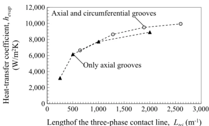
Fig. 13presents the evaporator heat-transfer coefficients of two SS-ammonia LHPs as a function of the TPCL length. One LHP has only axial grooves, whereas the other has both axial and circumfer-ential grooves. There is little difference in the effects of the TPCL length between the two LHP types. The width of the grooves in the configuration with only axial grooves is smaller than that in the configuration with both groove types for the same TPCL length. Therefore, the configuration with only axial grooves can experience problems during wick manufacturing.
0 5,000 10,000 15,000 20,000 25,000 30,000 0 500 1,000 1,500 2,000 2,500 3,000
H
ea
t-tr
an
sf
er
c
o
ef
fi
ci
en
t,
h
ev a p(W
/m
2K
)
Length of the three-phase contact line, L
tri(m
-1)
PTFE - ammonia Stainless steel - ammonia
Copper - water Classical C - W Classical S - A Classical P - A
Fig. 11. Evaporator heat-transfer coefficients of copper-water, SS-ammonia, and PTFE-ammonia LHPs as function of TPCL length. The applied heat flux is 6.25 W/ cm2
. The number of circumferential and axial grooves increases with an increase in the TPCL length.
(a) Stainless steel-ammonia
x-y plane
y-z plane
(b) PTFE-ammonia
(c) Copper-water
TPCL
Fig. 12. Distribution of heat flux vectors and liquid–vapor interface shape on x-y and y-z plane. The applied heat flux is 6.25 W/cm2. Both axial and circumferential grooves are created. The TPCL length is 2600 m!1.
5. Conclusions
This paper presented heat-transfer simulations in LHP evapora-tors using a three-dimensional pore network model. The results for different combinations of the wick material and working fluid, namely, SS-ammonia, PTFE-ammonia, and copper-water, were cal-culated for an evaporator with only axial grooves and for one with both circumferential and axial grooves.
I. The effect of the thermal conductivity of the wick and work-ing fluid on the transition heat flux from a saturated wick with liquid to an unsaturated wick with vapor and liquid was presented. Because different transition heat fluxes were obtained, when the optimum evaporator shape of the ammonia LHP was designed, it was reasonable to assume the phase state to be that of an unsaturated wick for the ammonia LHPs and that of a saturated wick for the copper-water LHPs.
II. It was found that heat flux concentrated at the TPCL within the case, wick, and grooves. The evaporator heat-transfer coefficients of the SS-ammonia, PTFE-ammonia, and copper-water LHPs were increased with increasing the TPCL length except the classical wick shape of the copper-water LHP. Results indicated that the optimum shape of the evap-orator could be realized by adjusting the TPCL length. In the future, detailed heat-transfer simulation at the TPCL should be performed.
Acknowledgement
This research was partly supported by JSPS KAKENHI Grant Number 15H06287 and by JST, PRESTO. A super computer system in the Information Technology Center of Nagoya University was used for the calculations.
References
[1] C. Figus, Y. Le Bray, S. Bories, M. Prat, Heat and mass transfer with phase change in a porous structure partially heated: continuum model and pore
network simulations, Int. J. Heat Mass Transf. 42 (1999) 2557–2569,http://dx. doi.org/10.1016/S0017-9310(98)00342-1.
[2] T.S. Zhao, Q. Liao, On capillary-driven flow and phase-change heat transfer in a porous structure heated by a finned surface: measurements and modeling, Int. J. Heat Mass Transf. 43 (2000) 1141–1155, http://dx.doi.org/10.1016/S0017-9310(99)00206-9.
[3] T. Kaya, J. Goldak, Numerical analysis of heat and mass transfer in the capillary structure of a loop heat pipe, Int. J. Heat Mass Transf. 49 (2006) 3211–3220,
http://dx.doi.org/10.1016/j.ijheatmasstransfer.2006.01.028.
[4] Z.M. Wan, W. Liu, Z.K. Tu, A. Nakayama, Conjugate numerical analysis of flow and heat transfer with phase change in a miniature flat plate CPL evaporator, Int. J. Heat Mass Transf. 52 (2009) 422–430, http://dx.doi.org/10.1016/j. ijheatmasstransfer.2008.06.019.
[5] M.A. Chernysheva, Y.F. Maydanik, 3D-model for heat and mass transfer simulation in flat evaporator of copper-water loop heat pipe, Appl. Therm. Eng. 33 (2012) 124–134,http://dx.doi.org/10.1016/j.applthermaleng.2011.09.025. [6] M.A. Chernysheva, Y.F. Maydanik, Simulation of thermal processes in a flat
evaporator of a copper–water loop heat pipe under uniform and concentrated heating, Int. J. Heat Mass Transf. 55 (2012) 7385–7397, http://dx.doi.org/ 10.1016/j.ijheatmasstransfer.2012.07.001.
[7] L. Ji, G.P. Peterson, 3D heat transfer analysis in a loop heat pipe evaporator with a fully saturated wick, Int. J. Heat Mass Transf. 54 (2011) 564–574,http://dx. doi.org/10.1016/j.ijheatmasstransfer.2010.09.014.
[8] L. Mottet, T. Coquard, M. Prat, Three dimensional liquid and vapour distribution in the wick of capillary evaporators, Int. J. Heat Mass Transf. 83 (2015) 636–651,http://dx.doi.org/10.1016/j.ijheatmasstransfer.2014.12.048. [9] M. Nishikawara, H. Nagano, L. Mottet, M. Prat, Formation of unsaturated
regions in the porous wick of a capillary evaporator, Int. J. Heat Mass Transf. 89 (2015) 588–595,http://dx.doi.org/10.1016/j.ijheatmasstransfer.2015.05.054. [10] M. Nishikawara, H. Nagano, M. Prat, Evaporator heat-transfer analysis of a loop
heat pipe with low thermal conductivity wicks, in: Proceedings of the 17th International Heat Pipe Conference, No. 18, Kanpur, October 2013. [11] M. Nishikawara, H. Nagano, L. Mottet, M. Prat, Numerical study of thermal
performance of a capillary evaporator in a loop heat pipe with liquid-saturated wick, J. Electron. Cool. Therm. Contr. 27 (2014) 118–127,http://dx.doi.org/ 10.4236/jectc.2014.44013.
[12] M. Nishikawara, H. Nagano, Numerical simulation of capillary evaporator with microgap in a loop heat pipe, Int. J. Therm. Sci. 102 (2016) 39–46,http://dx.doi. org/10.1016/j.ijthermalsci.2015.11.008.
[13] R. Hatakenaka, A. Okamoto, Y. Mase, M. Murakami, H. Iikura, Visualization of internal fluid behavior in a miniature loop heat pipe using neutron radiography, in: 41st International Conference on Environmental Systems, International Conference on Environmental Systems (ICES), AIAA 2011-5140, Oregon, July 2011.http://dx.doi.org/10.2514/6.2011-5140.
[14] E.W. Lemmon, M.L. Huber, M.O. McLinden, NIST Standard Reference Database 23: Reference Fluid Thermodynamic and Transport Properties-REFPROP, Version 9.1, National Institute of Standards and Technology, Standard Reference Data Program, Gaithersburg, 2013.
[15] M. Nishikawara, H. Nagano, Parametric experiments on a miniature loop heat pipe with PTFE wicks, Int. J. Therm. Sci. 85 (2014) 29–39,http://dx.doi.org/ 10.1016/j.ijthermalsci.2014.05.016.
[16] S.V. Vershinin, Y.F. Maydanik, Hysteresis phenomena in loop heat pipes, Appl. Therm. Eng. 27 (2007) 962–968, http://dx.doi.org/10.1016/j. applthermaleng.2006.08.016.
[17] R. Singh, A. Akbarzadeh, M. Mochizuki, Effect of wick characteristics on the thermal performance of the miniature loop heat pipe, J. Heat Transf. 131 (2009) 082601,http://dx.doi.org/10.1115/1.3109994.
[18] R.R. Riehl, N. dos Santos, Loop heat pipe performance enhancement using primary wick with circumferential grooves, Appl. Therm. Eng. 28 (2008) 1745– 1755,http://dx.doi.org/10.1016/j.applthermaleng.2007.11.005.
[19] M. Kuroi, H. Nagano, The influence of groove shape on loop heat pipe performance, Heat Pipe Sci. Technol. Int. J. 3 (2012) 203–222,http://dx.doi.org/ 10.1615/HeatPipeScieTech.2013006554.
[20]V.P. Carey, Liquid-Vapor Phase-Change Phenomena, second ed., Taylor & Francis, 2008, pp. 107–112.
[21] M. Nishikawara, H. Nagano, Numerical analysis of liquid-vapor thermo-fluid behavior in a loop heat pipe evaporator with pore network model (liquid-vapor phase distribution in a porous structure and heat-transfer characteristics), Therm. Sci. Eng. 23 (4) (2015) 71–80, http://dx.doi.org/ 10.11368/tse.23.71(in Japanese).
[22] M. Nishikawara, H. Nagano, Optimization of wick shape in a loop heat pipe for high heat transfer, Int. J. Heat Mass Transf. 104 (2017) 1083–1089,http://dx. doi.org/10.1016/j.ijheatmasstransfer.2016.09.027. 0 2,000 4,000 6,000 8,000 10,000 12,000 0 500 1,000 1,500 2,000 2,500 3,000
H
ea
t-tr
an
sf
er
c
o
ef
fi
ci
en
t,
h
ev a p(W
/m
2K
)
Lengthof the three-phase contact line, L
tri(m
-1)
Only axial grooves Axial and circumferential grooves
Fig. 13. Evaporator heat-transfer coefficient of SS-ammonia LHP as function of TPCL length. The applied heat flux is 6.25 W/cm2