TH `
ESE
TH `
ESE
En vue de l’obtention du
DOCTORAT DE L’UNIVERSIT´
E DE
TOULOUSE
D´elivr´e par : l’Universit´e Toulouse 3 Paul Sabatier (UT3 Paul Sabatier)
Pr´esent´ee et soutenue le Date de d´efense (08/07/2015) par :
Mohammad CHARAF EDDIN
Contribution to Dynamic Reconfiguration in
Component-based Systems:
Consistency and Non-functional Properties Specification
JURY
Yamine Ait-Ameur Professeur `a l’ENSEEIHT Examinateur Jean-Philippe Babau Professeur, Universit´e de
Bretagne Occidentale
Rapporteur Franck Barbier Professeur, Universit´e de
Pau
Rapporteur Claude Baron Professeur `a
l’INSA-Toulouse
Examinateur Carlos Cardeira Professeur `a l’universit´e de
Lisbonne
Examinateur Zoubir MAMMERI Professeur, Universit´e de
Toulouse
Directeur de Th`ese
´
Ecole doctorale et sp´ecialit´e :
MITT : Domaine STIC : R´eseaux, T´el´ecoms, Syst`emes et Architecture
Unit´e de Recherche :
Institut de Recherche en Informatique de Toulouse (IRIT - UMR 5505)
Directeur de Th`ese :
Zoubir MAMMERI
Rapporteurs :
The research of this thesis has two main goals. The first goal is to provide the recon-figurability feature to the component-based systems. The second goal is to select the optimal configuration from a set of configurations, which provide similar functionality. The selection process depends on the non-functional properties of the system.
Reconfigurability is essential feature for many contemporary component-based sys-tems. reconfigurability enhances the continuous availability, the adaptability, the evolv-ability, the maintainevolv-ability, and the performance. Avionics systems, telecommunications switches and some commercial systems require the high availability. For these systems, long shutting down is not allowable due to economical or safety reasons. The adapt-ability and the evolvadapt-ability are also important features for those systems which need to accommodate the the environmental changes or the new requirements of software users. the maintainability and the performance are important requirements for a large category of systems. All the previous motivations and more show the importance of having the reconfigurability.
Reconfigurability is the ability to change the system structure or the system behavior at running time without stopping it. The work presented in this thesis investigates the required mechanisms and techniques in order to provide the reconfigurability feature to a component-based system. The provision of the reconfigurability feature requires preserving the system consistency during and after the reconfiguration. The consistency has two kinds: global consistency and local consistency. In this thesis, we propose an approach to preserve the global consistency of a reconfigurable component-based system using declarative formal language. Another approach is proposed to preserve the local consistency during the reconfiguration. The second approach investigates the relationship between the indirect dependency and the dynamic reconfiguration.
Configuration selection is to select the most optimal configuration from a set of alter-natives in order to maximize the end user satisfaction. The thesis proposes an approach to make the best selection depending on the user preferences.
First of all, i would like to express profound gratitude to my advisor, Prof. Zoubir Mammeri, for his invaluable support, encouragement, supervision and useful suggestions throughout this research work. His moral support and continuous guidance enabled me to complete my work successfully. I also have to thank the members of my PhD committee professors Yamine Ait-Ameur, Jean-Philippe Babau, Franck Barbier, Claude Baron, and Carlos Cardeira for their helpful career advice and suggestions in general. I would like to acknowledge also all the members of IRIT.
I am as ever, especially indebted to my parents for their love and support throughout my life. I also wish to thank all my brothers for their support and understanding during my study. Moreover, my sincere thanks go to my wife and son , who shared their love with me. Finally, I wish to express my appreciation to all of my friends.
1 Introduction 1
1.1 Background of The Research . . . 1
1.1.1 Dynamic Reconfiguration . . . 1
1.1.2 Configuration Selection . . . 4
1.2 Research Requirements . . . 6
1.3 Contributions . . . 8
1.4 Thesis Plan . . . 9
2 Component-based Engineering and Dynamic Reconfiguration concepts 11 2.1 Software Components . . . 11
2.1.1 Definitions . . . 11
2.1.2 CBSE Characteristics . . . 13
2.2 Software Architecture . . . 13
2.2.1 Definition . . . 14
2.2.2 Software Architecture Characteristics . . . 14
2.3 Component Models . . . 15
2.3.1 CCM . . . 15
2.3.2 EJB . . . 16
2.3.3 .NET . . . 17
2.3.4 FRACTAL . . . 18
2.4 Architecture description language (ADL) . . . 19
2.5 Transaction-processing Component-based Systems . . . 23
2.6 Dynamic Reconfiguration Definition . . . 25
2.7 Motivations for Dynamic Reconfiguration . . . 25
2.8 Dynamic Reconfiguration Classifications . . . 27
2.8.1 Planned Reconfiguration . . . 27
2.8.2 Unpredictable Reconfiguration . . . 28
2.9 Dynamic Reconfiguration Challenges . . . 29
2.9.1 Global Consistency . . . 29
CONTENTS
2.10 Dynamic Reconfiguration Operations . . . 31
2.11 Conclusion . . . 34
3 Comparative Study of Dynamic Reconfiguration Approaches 35 3.1 Introduction . . . 35
3.2 Background . . . 35
3.3 Exploring the Comparison Criteria . . . 36
3.4 Dynamic Reconfiguration Approaches Survey . . . 39
3.5 Classification of Dynamic Reconfiguration Approaches . . . 53
3.6 Conclusion . . . 55
4 Preserving The Global Consistency of Dynamic Reconfiguration 59 4.1 Introduction . . . 59
4.2 Background . . . 60
4.2.1 Young and Magee’s Approach . . . 60
4.2.2 L´eger et al’s Approach . . . 60
4.2.3 Kacem et al’s Approach . . . 61
4.2.4 Requirements for a New Approach . . . 61
4.2.5 Methodology of The Proposed Approach . . . 61
4.3 Alloy Specification Language . . . 62
4.3.1 Definitions . . . 62
4.3.2 Alloy Language . . . 62
4.4 Modeling The Structure of a Configuration . . . 63
4.5 Modeling Dynamic Reconfiguration Operations . . . 67
4.6 Preserving the Global Consistency of Reconfigurable Systems . . . 69
4.7 Reconfiguring and Analyzing a Running System . . . 73
4.8 Conclusion . . . 76
5 Preserving The Local Consistency of Dynamic Reconfiguration 79 5.1 Introduction . . . 79
5.2 Working Environment . . . 80
5.2.1 State Change Commands . . . 82
5.2.2 Example . . . 82
5.3 State Transfer . . . 83
5.4 Problem . . . 83
5.5 Modeling The Dependency of Reconfigurable Systems . . . 85
5.6 Dynamic Reconfiguration Algorithm . . . 88
6 Non-functional Properties Aware Configuration Selection in
Component-based Systems 91
6.1 Introduction . . . 91
6.2 Background and assumptions . . . 92
6.2.1 Background . . . 92
6.2.2 Assumptions . . . 94
6.3 Modeling Non-functional Properties of Components Using Acme . . . 95
6.4 Preserving The Global Consistency . . . 97
6.5 Non-functional Properties Normalization . . . 99
6.5.1 Boolean Values Normalization . . . 99
6.5.2 Numeric Values Normalization . . . 99
6.5.3 String Values Normalization . . . 100
6.5.4 Example . . . 100
6.6 Evaluating Mono-component Configurations Using Non-functional properties101 6.6.1 WSM Evaluation . . . 101
6.7 Example . . . 102
6.7.1 Generating The prospective Configurations . . . 103
6.7.2 Filtering Phase . . . 103
6.7.3 Normalization Phase . . . 104
6.7.4 Evaluating The Alternatives Phase . . . 104
6.7.5 Applying The Selected Configuration Phase . . . 105
6.8 Conclusion . . . 105
7 Conclusions and Directions for Future Work 107 7.1 Conclusion . . . 107
1.1 Consistency categories . . . 2
1.2 The summary of dynamic reconfiguration . . . 3
1.3 The architecture of an autonomous reconfigurable component-based system 4 1.4 A mobile component-based operating system . . . 5
1.5 Different configurations provide similar functionality . . . 5
2.1 The UML component diagram . . . 12
2.2 Darwin ADL example . . . 20
2.3 Wright ADL example . . . 21
2.4 Acme ADL example . . . 22
2.5 Acme repair strategy . . . 23
2.6 Three-Tier Architecture . . . 24
2.7 shows a programmed reconfigurable system model . . . 27
2.8 shows an unpredictable reconfigurable system model . . . 28
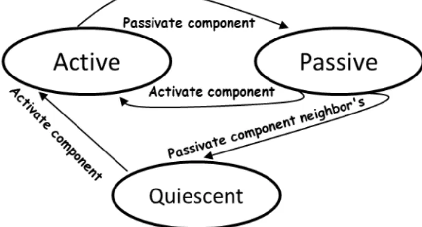
2.9 Component state diagram . . . 31
2.10 Adding new component to a component-based system . . . 31
2.11 Removing an existing component . . . 32
2.12 Connecting two components . . . 33
2.13 Disconnecting two components . . . 33
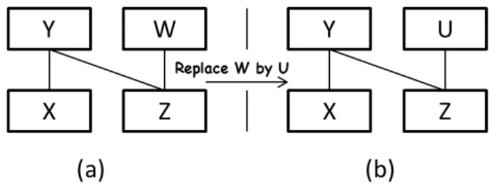
2.14 Replacing an existing component by a new one . . . 34
3.1 Working areas which are addressed by dynamic reconfiguration approaches 53 3.2 Transparent and nontransparent dynamic reconfiguration . . . 54
3.3 Consistency preservation approaches . . . 54
4.1 A simple example of linked list modeling . . . 63
4.2 A structural model for a configuration . . . 64
4.3 Client Server example . . . 65
4.4 Relations graph generated by Alloy Analyzer . . . 66
4.5 A general form of a dynamic reconfiguration operation . . . 68
LIST OF FIGURES
4.7 An assertion to check whether all required interfaces are connected or not 70
4.8 Executing check NoFreeReqInt . . . 71
4.9 Executing check NoFreeReqInt where the analyzer finds Counterexample 72 4.10 Relations graph generated by Alloy Analyzer shows i6 is not connected . 72 4.11 shows the different stages of reconfiguring a running system . . . 73
4.12 Evolution of a system at runtime . . . 74
4.13 Executing the command run Configure . . . 76
4.14 The relations graph of conf1 and conf2 . . . 76
5.1 Example of independent transaction . . . 81
5.2 Example of dependent transaction . . . 81
5.3 Driving the component Z to the quiescent state . . . . 83
5.4 Secure distributed producer\consumer system . . . 84
5.5 A structural model for a configuration . . . 86
5.6 Evolution of a system at runtime . . . 87
5.7 This function returns the indirect dependency set for a specific component 87 5.8 An assertion to check whether a specific component has any indirect de-pendable relations or not . . . 88
6.1 Part (A):The architecture of an autonomous reconfigurable component-based system. Part(B): shows different configurations provide similar func-tionality . . . 95
6.2 Search engine description with some non-functional properties . . . 96
6.3 Weighted non-functional property type . . . 96
6.4 Illustrative example using Acme modeling language . . . 98
3.1 Working areas, change granularity and frameworks . . . 56
3.2 Change script, middleware and preserved consistency . . . 57
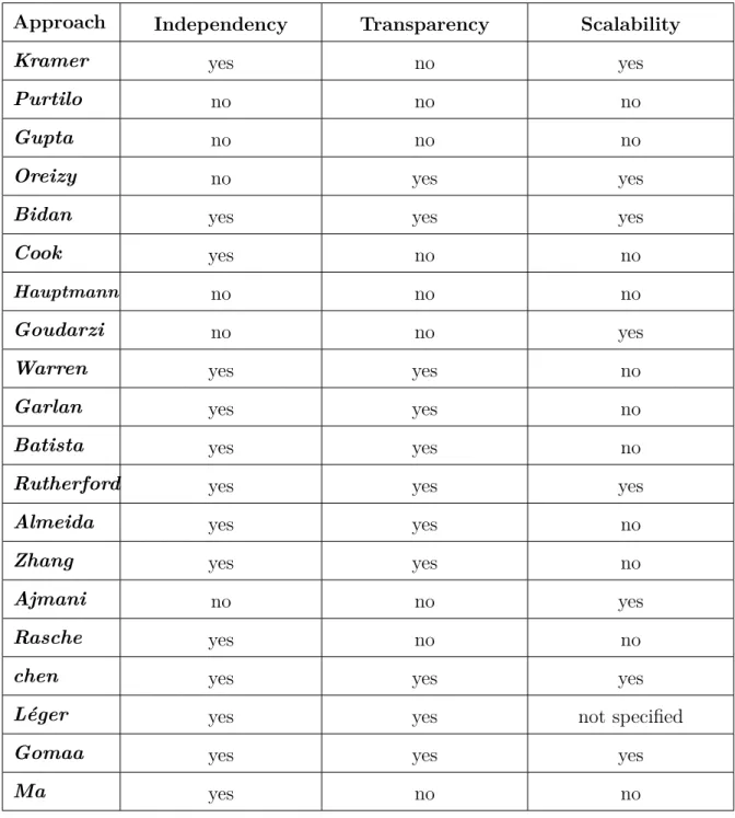
3.3 Independency, transparency, and scalability . . . 58
4.1 belongrelation . . . 65
4.2 have relation . . . 65
4.3 contain relation . . . 66
4.4 bindings relation . . . 66
6.1 Security NFP normalization . . . 100
6.2 normalization the real values of NFPs in fig 6.4 . . . 100
6.3 NFPs values of the messengers and the internet connections . . . 103
Introduction
This chapter presents and introduces the thesis. It provides a brief background about the topic, the investigated problem, the proposed approaches and the thesis plan.
1.1
Background of The Research
The research of this thesis has two main objectives. The first axis is to support the reconfigurability feature to the component-based systems 1. The second axis is to select
the optimal configuration from a set of configurations which provide similar functionality. The selection process depends on the non-functional properties of the system.
The research investigates the two axes in the component-based systems domain. Component-Based Software Engineering (CBSE) [SGM02, HC01] is a powerful technology to create complex systems because it provides strong features like assembling the build-ing blocks (components) to build complex modular system, software reuse, and complex management.
1.1.1
Dynamic Reconfiguration
A reconfigurable system has the ability to change its structure and behavior during the execution time without the need to restart or to stop the system.
Adding the reconfigurability feature to component-based systems is very essential in order to build autonomous and adaptive systems. There are several motivations for supporting dynamic reconfiguration in contemporary component-based systems. Some of these motivations are: High availability, adaptability, evolvability, maintainability, and performance. High available systems aim to change their configuration at execution time without stopping or restarting them. Another important class of software systems need to accommodate the environmental changes or the new requirements of software
1.1. BACKGROUND OF THE RESEARCH
users. Furthermore, the evolving runtime environments require the system to provide the reconfigurability feature in order to satisfy the unpredictable changes. Dynamic reconfiguration can help such systems to satisfy these requirements.
There are various kinds of software systems which aim to possess the reconfigurability feature. Examples include systems such as avionics systems, telecommunications switches and some commercial systems. For these systems the continuous availability is a critical requirement in order to work correctly. Also, adaptable systems and autonomous systems need to have the reconfigurability feature in order to adapt the continuous change in the working environment.
Figure 1.1: Consistency categories
To this end, we explain briefly the meaning of the dynamic reconfiguration term and we give some example of systems need the reconfigurability feature. But, someone may ask the following question: Many operating systems and middleware provide some
tools for loading and unloading the components (e.g., dynamic link libraries in UNIX) at running time without the need to restart the system, so what is the difference between the previous tools and the dynamic reconfiguration? The answer is the previous tools
can modify the system at runtime but they do not have any support for consistency preservation, correctness and state transfer 2. Using the previous tools may leave the system in an inconsistent state and may break the system correctness.
Therefore, the essential point of dynamic reconfiguration is to change the system at running time without the need to stop it and to preserve the system consistency
during and after the reconfiguration. In this research, the majority of work is
focusing on preserving the system consistency during and after the change. So, what is the meaning of the consistency?
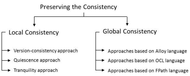
In fact, the consistency (cf. figure 1.1) can be divided into two categories: The global consistency and the local consistency. Global consistency means to satisfy the system invariants. This is done by preventing the reconfiguration operations from violating the system invariants. An example of system invariants would be: In a binary tree, there are at most two children for each node. Local consistency means to prevent the
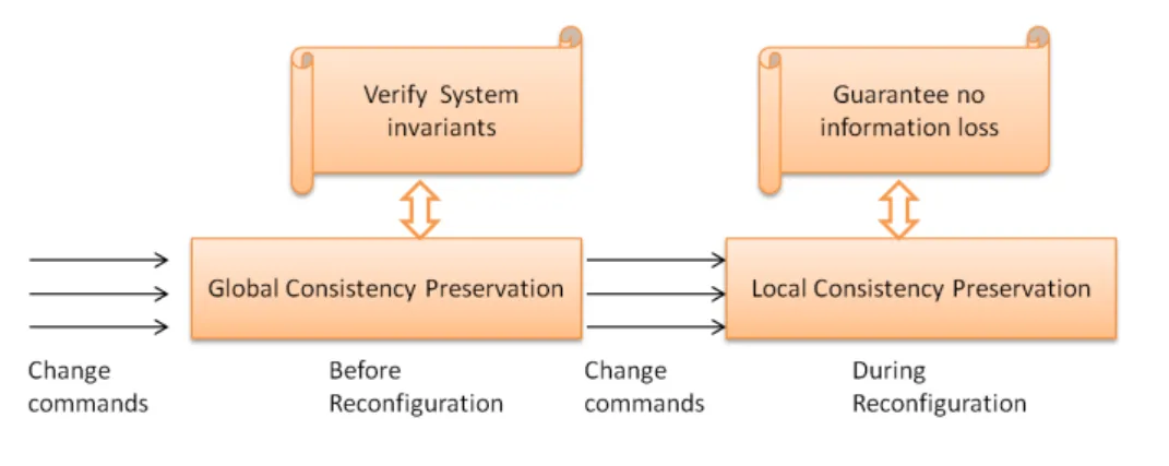
information loss. For example, if the reconfiguration manager wants to replace an old version of a component by a new version of this component then, the reconfiguration should guarantee that the current status of the old component will be transferred to the new one. Preserving the local consistency in reconfigurable systems, during and after the reconfiguration process, is a tedious task[KM90, BISZ98]. Several works have been done in the literature to preserve the local consistency. One of the most popular works is done by Kramer and Magee[KM90]. They proved that the quiescence criterion or the safe state criterion was sufficient to ensure the local consistency during the reconfiguration of a distributed system. Figure 1.2 shows the sequence of the preserving of the system consistency during the reconfiguration process.
Figure 1.2: The summary of dynamic reconfiguration
First of all, the system receives a set of reconfiguration (change) commands. Then, a verification step should be done to ensure the preserving of the global consistency. That’s to say, all system constraints should be satisfied. If the reconfiguration commands violate the system invariants then the reconfiguration commands are rejected. If the reconfigura-tion commands satisfy the system invariants then the global consistency is preserved and the reconfiguration process can be started. During and after the reconfiguration process the local consistency should be preserved (no information loss). Usually, local consistency preservation is done by driving the system to a safe state. When the safe state is reached then, it is possible to reconfigure the target component.
The reconfiguration operations make structural modifications in order to change the system behavior or the system structure. In this research, we take into consideration five kinds of dynamic reconfiguration primitives. The following list shows these primitives:
1. Add primitive: aims to add a new component to the current system.
2. Remove primitive: aims to remove a new component from the current system. 3. Link primitive: aims to add a new link between two interfaces.
1.1. BACKGROUND OF THE RESEARCH
5. Replace primitive: aims to replace an existing component from the current system by a new component.
1.1.2
Configuration Selection
The goal of the research in this axis is to propose an approach which enables an au-tonomous system to choose the most preferred configuration from a set of alternatives in order to maximize the end user satisfaction. An autonomous reconfigurable component-based system is a system which has the ability to change itself by self-reconfiguring. Figure 1.3 shows the architecture of an autonomous reconfigurable component-based system. The architecture has several layers.
Figure 1.3: The architecture of an autonomous reconfigurable component-based system Let us present the role of each layer from the bottom to the top. At the lower layer, the system has a pool of components where each component provides some services via its interfaces. The desired functionality can be provided by assembling some components in a specific configuration. The reconfiguration management layer is responsible for recon-figuring the components and assemble them in order to construct a configuration which can provide the desired functionality. The reconfiguration management unit supports the five essential operations of dynamic reconfiguration: add components, remove, link, unlink, replace.
The analysis and decision making layer is responsible for analyzing the collected infor-mation in order to take the correct decision. The collected inforinfor-mation has two sources: the monitoring unit and the end user. The monitoring unit gathers the information about the working environment and conveys them to the analysis and decision making layer to adapt the working environment changes. The end user can also ask the system to reconfigure itself to provide the new requirements of the user.
the user requirements or information about the working environment. The analysis and decision making layer is responsible to analyze the received data and to take the decision whether the system should be reconfigured or not. If the system should be reconfigured then this layer should provide the model of the new configuration. The reconfiguration management layer implements the model on the components layer.
Figure 1.4: A mobile component-based operating system
Figure 1.5: Different configurations provide similar functionality
The investigation made in this thesis is focused on the analysis and decision making layer. If the reconfiguration decision has been taken then, this layer is responsible for providing the model of the new configuration. In many cases, this layer can find many different models, each of them provides the same desired functionality. For example, suppose that we have a mobile component-based operating system 1.4. The user wants to get access to the map browser in order to get some information about his or her location. The desired information may be road map or schools or hotels etc.. Therefore, the system should change its configuration from the current configuration Conf to a new configuration which provides the desired functionality (map browsing in this case). A reconfiguration decision has been taken to modify the current configuration Conf in order to provide the map browsing functionality . The analysis shows that there are three new models which can provide the desired functionality Conf01, Conf02, and Conf03 (figure 1.5).
• Conf01 depends on using the GPS service and it contains the components Map
Browser and GPS Driver. The GPS service is free (advantage), however it consumes
1.2. RESEARCH REQUIREMENTS
• Conf02 depends on using the WiFi service and it contains the components Map
Browser and WiFi Driver. The WiFi service is fast (advantage), however it is very
expensive (drawback).
• Conf03 depends on using the Data Connection service and it contains the
compo-nents Map Browser and Data Connection Driver. The Data Connection service is less expensive (advantage), however it is very slow (drawback).
So the question which reconfiguration model should be chosen? The thesis proposes
an approach which uses the non-functional properties (such as price, power consumption,
response time) in order to select the most optimal configuration model. Non-functional
properties such as price, power consumption, speed, etc. can be used to specify the user preferences. The goal of the research is to select the configuration model, which can maximize the user satisfaction by exploiting the non-functional properties.
1.2
Research Requirements
The work described in this thesis considers the following requirements: 1. Component-based structure
A reconfigurable software system should be modular. This means that the structure of the system consists of several entities connected to each other. Usually, these entities represent the unit of change.
A dynamic reconfiguration approach may change statements or procedures or mod-ules or objects or components or even subsystems. It is very recommended to focus on the big picture by looking at the system as a set of components rather than diving to the statements and variables depths. The work made in this thesis adopts the component-based structure.
2. Declarative structural formal specification
Building reconfigurable component-based systems requires the ability to specify the structure and the behavior of a reconfigurable system. The reconfigurability implies the specification should model the structure of the system and the dynamic aspects.
In the thesis we use Alloy [Jac06] specification language to model the structure and the dynamic aspects of a reconfigurable system. There are many motivations behind choosing Alloy language. Alloy is a lightweight, scalable, high performance language. Alloy also is based on formal specification and is amenable to a fully automated analysis.
3. Structural constraints representation
Preserving the global consistency of a reconfigurable system requires the satisfaction of a set of constraints about its structure. Usually, we express these constraints as facts. A reconfiguration operation is considered as a valid operation if it satisfies the whole set of the structural constraints. For example, to prevent the self-binding we may express this constraint by the following fact: A component cannot bind to itself. This can prevent the self-relation.
Respecting the satisfaction of the set of constraints is very important to ensure the consistency during and after the reconfiguration process.
4. Run-time analyzing
Dynamic reconfiguration commands analyzer should always preserve the system consistency. Therefore, these commands are analyzed at the running time to check whether they can produce a new consistent system (configuration) or not. A con-sistent configuration is compliant with the system model.
Alloy analyzer is used to check whether the reconfiguration commands can be exe-cuted or not. Acceptable reconfiguration commands should not violate the system invariants.
5. Safe state
Usually, in order to preserve the local consistency of the system. Dynamic recon-figuration approaches should put the affected components in a safe state before reconfiguring them. Safe state comprises two things. The first one, the target com-ponent must be frozen or inactive. That’s to say the comcom-ponent do not send or receive or process any information. The second one, the target component should be isolated from the unaffected components. The reconfiguration approaches differ from each other in the way they use to reach the safe state.
6. Explicit specification of non-functional properties
Getting benefit from the non-functional properties in order to select the most op-timal configuration according to the user preferences requires explicit specification non-functional properties. The thesis uses Acme [GMW10] description language. Acme is an Architecture Description Language (ADL). We choose Acme because it has the ability to model and to specify the non-functional properties. It uses the components to represent the structure of the system. Connectors are used to represent the different connections between components. In Acme modeling a com-ponent may have properties. There are two types of properties: functional and non-functional. Functional properties are used to represent the computational be-havior of the component. Non-functional properties is used to represent the system qualities. For example, performance, delay, price, and reliability.
1.3. CONTRIBUTIONS
1.3
Contributions
The primary contribution of this work is to provide a comparative study between various dynamic reconfiguration approaches by exploring the features of these approaches and to classify them with respect to these features.
The comparative study starts by exploring the comparison criteria. Then, it surveys several approaches for supporting dynamic reconfiguration. The approaches are selected from various software models. This work has been presented in [Edd13].
The second contribution proposes an approach for preserving the global consistency during the reconfiguration. The approach has three major steps: Firstly, it proposes a general model to specify the system structure using a formal specification language and then it proposes a set of constraints to represent the system invariants. Respecting the satisfaction of the set of constraints is very important to ensure the consistency during and after the reconfiguration process. Finally, we use an analyzer in order to analyze the proposed model.
Different approaches have been proposed to preserve the global consistency. The com-mon thing between these approaches is to model, specify, and constrain the dynamically reconfigurable systems. However, none of them uses a formal specification language which has an analyzer such as Alloy language [Jac06]. Alloy analyzer provides fully automated analysis. This work has been presented in [CEM13].
The third contribution proposes an approach, which investigates the relationship be-tween the indirect dependency and the dynamic reconfiguration in the component-based systems.
Usually, a Component-Based System has two kinds of dependencies. The first one is the direct dependency which arises from the direct connections of each component with its neighbors. The other kind is the indirect dependency which arises from the uncon-nected components which potentially depend on each other. The approach proposes a new algorithm of dynamic reconfiguration, which takes in consideration the indirect de-pendency between the components. This work has been presented in [CEM14a].
The fourth contribution is about choosing the most preferred configuration from a set of alternatives in order to maximize the end user satisfaction. The proposed approach is based on using a list of non-functional properties (NFP) of components such as price, speed, performance, etc. The proposed approach starts by presenting how to model the structure of a component-based system. The model should specify both the functional and the non-functional properties. Having a comprehensive model is an essential issue at the analyzing and decision making time. Then, the approach shows how to check whether
a configuration preserves the system consistency or not. After that it presents non-functional properties normalization and configuration evaluation method. The evaluation process exploits multi-criteria decision making methods (MCDA) [Tri00] to assess the configurations according to the non-functional properties.
1.4
Thesis Plan
The thesis has seven chapters, the first chapter, which is the introduction chapter is already presented. The rest of chapters are presented briefly below.
• Chapter 2
In the second chapter we provide a general background on dynamic reconfiguration (definitions, motivations, classifications of dynamic reconfiguration types, etc.). • Chapter 3
Chapter 3 surveys some of the proposed approaches in the literature. Then, it shows the differences between these approaches by comparing them and classifying them according to a set of criteria.
• Chapter 4
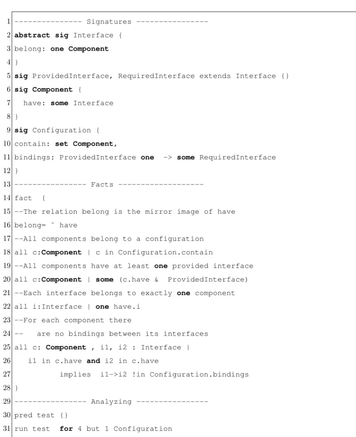
Chapter 4 proposes an approach to preserve the global consistency of a reconfig-urable component-based system. The approach starts by specifying a general model using a declarative formal language (Alloy). We have shown that the system struc-ture can be modeled by using Alloy signastruc-tures and relations. Additional relations and facts can be added to this model to represent any structure.
To model the reconfigurability, we have used Alloy predicates. Each predicate rep-resents a reconfiguration operation. Multiple predicates can be gathered in another predicate to represent the desired reconfiguration commands. Preserving the global consistency means to respect the system invariants. In Alloy, system invariants can be modeled by using facts. Finally, we have showed the benefit of using automated formal language by running many tests to check the safety of the reconfiguration commands. We can decide by using Alloy analyzer whether the reconfiguration operations preserve the global consistency or not.
• Chapter 5
Chapter 5 investigates the relationship between the indirect dependency of the system components and the dynamic reconfiguration. It proposes a new algorithm of dynamic reconfiguration, which takes in consideration the indirect dependency between the components.
1.4. THESIS PLAN
The proposed approach models the indirect dependency between the components of a component-based system. The model is written by using Alloy language. • Chapter 6
Chapter 6 presents an adaptive approach to select the most appropriate configura-tion from a set of configuraconfigura-tions which provide similar funcconfigura-tionality. The goal is to maximize the user satisfaction. The approach starts by proposing a model us-ing Acme language, which allows us to model the non-functional properties. Then we discuss how to preserve the global consistency in order to ensure the system correctness.
After that, we show how to specify the NFPs so that they can be used in the evaluation functions. Finally, we show how to evaluate and select the most optimal configuration according to the user preferences.
• Chapter 7
Component-based Engineering and
Dynamic Reconfiguration concepts
In this Chapter we provide a general knowledge of the basics of component-based en-gineering and dynamic reconfiguration. We start by presenting a general background about the CBE concepts. Then we explain the dynamic reconfiguration concepts and what are the motivations and the goals for adding the dynamic reconfiguration feature to an application or to a system. Then, what are the the challenges of adding dynamic reconfiguration feature. Finally, we present the five essential operations of dynamic re-configuration.
2.1
Software Components
2.1.1
Definitions
• Component-based software engineering (CBSE)
is a class of software engineering that emphasizes the design and construction of computer-based systems using reusable software.
• A software component
is a unit of composition with contractually specified interfaces and explicit context dependencies only. A software component can be deployed independently and is subject to composition by third parties [SGM02].
Szyperski’s definition contains the following characteristic properties of components:
1. A unit of composition by third parties
for component to be composable with other components, it should be self-contained. In addition, it should have a clear specification of what it requires or provides. That’s to say, a component should encapsulate its implementation and interact
2.1. SOFTWARE COMPONENTS
with its environment using interfaces. Third party is one that cannot be expected to have access to the construction details of the component.
2. A unit of independent deployment
for component to be independently deployable, it should be well separated from its environment and other components. Therefore, the component should encapsulate its constituent features as it is a unit of deployment, a component will never be deployed partially.
3. Contractual interfaces
interfaces are the means by which components can connect. Interfaces define the components access points. When a component offers services to the others, it implements a provided interface that specifies the services that other components can utilize, and how they can use them. However, when a component needs to use another component in order to function and work correctly, it adopts a required
interface that specifies the services that it needs. A useful way to view interfaces
specifications is as contracts between a client of an interface and a provider of an implementation of the interface. The contract states two things. The first one is what the client needs to do to use the interface. The second one is what the provider has to implement to meet the services promised by the interface.
4. Explicit context dependencies
context dependencies refer to the context of composition and deployment. They include the component model that defines the rules of composition and the com-ponent platform that defines the rules of deployment, installation, and activation of components. So, according to the component definition, the components should specifies their needs explicitly.
Figure 2.1: The UML component diagram
Figure 2.1 shows a UML component diagram. The main purpose of the component diagram is to show the structural relationships between the components of the system. In UML 2, the component is modeled by drawing rectangle with the component’s name in it
with interface symbols connect to it. A provided interface is represented using interface symbol with a complete circle at their end. A required interface is represented using interface symbol with only a half circle at their end.
2.1.2
CBSE Characteristics
Component-based software engineering (CBSE) has a lot of features. The following list states the essential ones:
• Effective reuse
CBSE is an approach that relies on software reuse. It emerged from the failure of object-oriented development to support effective reuse. The main idea behind CBSE is to reuse the component in different applications. However, in order to reuse the component, a set of constraints should be satisfied such as: good documentation (component specification), similar architecture and well-organized reuse process. • Substitutability
substitutability means replacing a component or a part of an implementation with another component or another art of an implementation.
• Independency
Components are independent so do not interfere with each other because each com-ponent see the other comcom-ponent as a black box. The only way for comcom-ponents to react with each other is to communicate through well-defined interfaces.
• Extensibility
The system can be extended either by adding new additional components or be extending the functionality of certain component in order to do new tasks.
• Better quality and lower costs
CBSE increases quality, especially evolvability and maintainability. CBSE also shortens development time and increases the productivity. Component platforms are shared and therefore, development costs are reduced.
2.2
Software Architecture
In this section, we give some of the background of software architecture because the approaches proposed in this thesis focus on the high-level view of the component-based system parts.
2.2. SOFTWARE ARCHITECTURE
2.2.1
Definition
According to [Gro00], the formal definition of software architecture is:
the fundamental organization of a system, embodied in its components, their relationships to each other and the environment, and the principles governing its design and evolution.
From the previous definition, we can extract the main concepts of the software archi-tecture.
• A software architecture is the high level design which specifies the system organi-zation.
• A software architecture comprises a collection of software components and the re-lations between them.
• A software architecture includes the principles, the constraints, and the guidelines governing its design and evolution over time.
2.2.2
Software Architecture Characteristics
Software Architecture has a lot of features. The following list exhibits the essential ones: • Separation of concerns
The software architecture reduces the high complexity of modern systems by sepa-rating the stakeholders concerns. A system stakeholder is an individual, team, or organization with concerns relative to a system. Usually, an architectural descrip-tion is organized into one or more architectural views. Each view addresses one or more of the concerns of the system stakeholders.
• Quality addressing
Software architecture is the first design artifact where a system’s quality attributes are addressed. Quality of an architectural description refers to its capability to meet the needs and concerns of the stakeholders for whom it was constructed. Some qual-ities are observable via execution such as performance, security, availability, func-tionality, usability. And some are not observable via execution: reconfigurability, modifiability, portability, reusability, integrability, testability.
• High-level view
Software architecture is a high-level design which represents an overall vision of what it should do and how it should do it. software architecture does not describe how the components or connections are implemented? or what are the languages or protocols used during the implementation?.
• System analysis
Software architecture enables the analysis of the system before the system has been built or before the system reconfiguration. The analysis gives the ability to verify whether the future system or the future configuration can satisfy the requirements or not.
2.3
Component Models
Component model is a definition of standards for component implementation, documen-tation and deployment. There are several different component models for developing component-based software. A popular examples are: Common Object Request Broker Architecture (CORBA) component Model, Enterprise JavaBeans (EJB) model, Compo-nent Object Model (COM) model, .NET model and Fractal compoCompo-nent model. In the following subsections, we briefly introduce each model.
2.3.1
CCM
The CORBA Component Model (CCM) is a specification for creating server-side scal-able, transactional, multi-user and secure enterprise-level applications. CCM extends Corba object model to support the concept of components and establishes standards for implementing, packaging, assembling, and deploying component implementations.
The CCM specification defines the four following models:
1. The CCM abstract model which enables developers to define interfaces and prop-erties of components.
2. The CCM programming model which defines both the Component Implementa-tion DefiniImplementa-tion Language (CIDL) and the Component ImplementaImplementa-tion Framework (CIF).
3. The CCM deployment model which defines the packaging and deployment tools. 4. The CCM execution model which defines containers as the technological artifacts.
A container is a runtime environment for component instances and their homes. Several containers could be hosted by a same component server.
The CORBA component model has a lot of features. The following list shows some of them:
• A standard development process:
2.3. COMPONENT MODELS
applications. CCM defines different roles: component designer (OMG IDL), com-ponent implementer (OMG CIDL), comcom-ponent packager, and comcom-ponent deployer. CCM addresses the concerns of each role.
• Automatized distributed deployment and configuration process:
The CORBA component model automates the deployment of component assem-blies to component servers. It provides an automatized distributed deployment and configuration process: to install the various component implementations of an ap-plication on a set of distributed nodes, to create component instances, to configure their attributes, to interconnect the created components, to start the components. • The interoperability standard:
The interoperability standard is one of the key features of CCM standards. CCM application can contain an assembly of EJB and CCM components. The CCM-EJB standard enables to bridge the gap between CCM-EJB environments and CCM environments.
2.3.2
EJB
The Enterprise Java Beans is a managed, server-side component architecture for the development and deployment of distributed enterprise applications. Applications written using the Enterprise Java Beans architecture can be written once, and deployed on any server platform that supports the Enterprise Java Beans specification.
The goal of Enterprise Java Beans is to construct and to build scalable, transactional, and secure applications. With EJB the business object can be: distributed, secure, transactional, persistent.
The Enterprise Java Beans component model has the following important features: • Server-side components:
EJB components are server-side components written entirely in the Java program-ming language. Server-side components are reusable, prepackaged pieces of appli-cation functionality that are designed to run in an appliappli-cation server.
• Standard infrastructure services:
There are different services automatically managed for the EJB component by the EJB server. These services include: persistence management, life cycle manage-ment, security managemanage-ment, distributed transaction managemanage-ment, concurrent ac-cess management, load balancing, fault tolerance etc.
• Self-contained components:
components. EJB components contain business logic only, they are only contain the code necessary to implement their services. No System-level programming Compo-nents is required.
• Portability:
EJB components are fully portable across any EJB server and any OS, work with any client. The EJB environment automatically maps the component to the un-derlying vendor-specific infrastructure services.
• Simplifying development:
The EJB architecture provides an integrated application framework. An EJB server automatically manages a number of middleware services on behalf of the application components. EJB component developers can concentrate on writing business logic rather than complex middleware.
2.3.3
.NET
The Microsoft .NET framework is a platform for designing, building, deploying, and running secured .NET software components to be integrated in highly distributed ap-plications and for developing XML web services. Microsoft .Net aims to simplify the development process of distributed applications.
Microsoft .Net provides component-based, multi-languages environment for integrat-ing existintegrat-ing applications with internet to meet the challenges of new applications for deployment and operation of internet-scale applications.
The primary component of Microsoft .NET are: 1. Common Language Runtime (CLR)
Common Language Runtime is a virtual machine environment like Java virtual machine (JVM) sitting on the top of Windows operating system. CLR consists of Common Type System (CTS), Just-In-Time IL Compiler (JIT), Execution unit, plus some other management services such as garbage collection and security man-agement.
2. .NET System Class Libraries
The .NET framework class library is a collection of reusable basic classes that tightly integrate with the runtime. The framework class library collects all classes including Windows Foundation Classes (WFC), Web Forms (the forms engine for ASP.NET).
3. ASP.NET used to create XML Web Services
2.3. COMPONENT MODELS
application framework designed for Web development to build dynamic web sites, web applications and web services.
The .Net component model has a lot of features. The following list shows some of them: • Language interoperability:
Microsoft .Net provides language interoperability. That’s to say each programming language can use code written in other programming languages.
• Strong emphasis on Web connectivity:
using XML web services to connect and share data between smart client devices, servers, and developers/users.
• Platform/language independent.
2.3.4
FRACTAL
Fractal [BCL+06a] is a modular component model that can be used to design, implement,
deploy and reconfigure systems and applications, from operating systems to middleware platforms and to graphical user interfaces.
The goal of Fractal is to reduce the development, deployment and maintenance costs of software systems in general, and of ObjectWeb projects in particular.
The Fractal component model has the following important features: • recursivity:
components can be nested in composite components. • Reflectivity:
Components have full introspection and intercession capabilities. • Component sharing:
A given component instance can be included (or shared) by more than one compo-nent. This is useful to model shared resources such as memory manager or device drivers for instance.
• Binding components:
A single abstraction for components connections that is called bindings. Bindings can embed any communication semantics from synchronous method calls to remote procedure calls
• Execution model independence:
No execution model is imposed. In that, components can be run within other execution models than the classical thread-based model such as event-based models and so on.
• Open:
Extra-functional services associated with a component can be customized through the notion of a control membrane.
2.4
Architecture description language (ADL)
Architecture description languages (ADLs) are formal languages to describe and represent software architectures. Some sophisticated ADLs also support the analysis of the software architecture. ADLs have graphical representation with a textual form and a formally defined syntax and semantics. ADLs focus on non-functional requirements of software systems. In order to describe the system architecture, ADLs should support the following building blocks:
Components, interfaces, connectors and configurations.
There are variety of architecture description languages have been developed in both the academic and the industrial domains. In this thesis we present briefly three of the ADLs: Acme, Darwin, Wright.
The reason behind choosing the previous ADLs is their ability to model and describe the dynamic aspects. Here are some examples of dynamic aspects may exist in several ADLs: • Lazy instantiation of components: a specific component is only instantiated when
any other component tries to use it.
• Specifying the non-functional properties of the components, constraining them, and the ability to launch a repair strategy at the runtime if the constraints are violated.
Darwin (ADL)
Darwin [MK96b] is a general purpose architecture description language (ADL). The es-sential goal of Darwin language is to model the structure of a software system. it uses both textual and graphical modeling. Darwin describes the system architecture in terms of components, interfaces (ports), and bindings. Components can be either primitive or composite. A composite component contains a number of subcomponents, and a number of bindings which describe the connections between the ports of the subcomponents. A component port either provides or requires a specific service.
Figure 2.2 shows an example of Darwin ADL. The example contains both the textual and the graphical representation. A filled circle in the graphical form indicates a provided interface (port), however, the empty one represents a required interface. The textual description shows how to define three components using the keyword component. Then we instantiate a component using the keyword inst. The bindings between the components ports is defined by using the keyword bind. The dynamic aspect in Darwin ADL is defined
2.4. ARCHITECTURE DESCRIPTION LANGUAGE (ADL)
by the dyn keyword which allows the lazy instantiation of components. For example, in figure 2.2 , the component z is only instantiated when x tries to use it.
Figure 2.2: Darwin ADL example
Wright (ADL)
The Wright Architecture Description Language [AG97, ADG98] can be used to provide a formal architectural specification and to analyze both the architecture of individual software systems and of families of systems. Wright describes the system architecture in terms of components, ports, connectors, and roles. Wright syntax is based on the notations of Communicating Sequential Processes (CSP) which gives the ability to specify the behavior of the components, the connectors and the systems.
The component type is described as a set of ports and a component-spec which specifies the abstract behavior of the component. A connector type defines a set of roles and a glue specification. The roles describe the expected local behavior of each of the interacting parties. The glue specification describes how the roles activities are coordinated.
According to [ADG98], dynamic Wright is based on the separation between the dy-namic reconfiguration behavior of an architecture and its non-reconfiguration functional-ity. The separation was made introducing the component configuror. This component is responsible for specifying the dynamic behavior in terms of reconfiguration actions such as new, del,attach and detach.
Figure 2.3 shows an example of architecture description of a simple client server system using Wright ADL. The example defines the client and the server components. It also defines the connector connect which contains the protocol of receiving the client requests and returning the result, then it instantiates a server, a client and a connector. Finally it connects the client c and the server s using the connector con.
1 System client-server 2 Component client =
3 port send-request = [behavioral spec] 4 spec = [behavioral spec]
5 Component server =
6 port receive-request= [behavioral spec] 7 spec = [behavioral spec]
8 Connector connect =
9 role caller = (request!x -> result?x ->caller) ˆ STOP 10 role callee = (invoke?x -> return!x -> callee) [] STOP 11 glue = (caller.request?x -> callee.invoke!x
12 -> callee.return?x -> callee.result!x 13 -> glue) [] STOP 14 Instances 15 s : server 16 c : client 17 con : connect 18 Attachments : 19 client.send-request as con.caller 20 server.receive-request as con.callee 21 end client-server.
Figure 2.3: Wright ADL example
Acme (ADL)
Acme is a software architecture description language (ADL) [GMW10]. It provides a set of language constructs for describing architectural structure, architectural types, styles and architectural elements properties. Acme has seven types of entities for architectural representation, the most basic elements of these entities are: components, connectors, and systems.
The components represents the primary computational elements and data stores of a system. The connectors represent interactions between components. The Systems represent configurations of components and connectors.
One of the most important features of Acme is the provision of annotation of ar-chitectural structure with lists of properties. This annotation can add more auxiliary information about the system over the structure description. For example, information about the power consumption, the communication speed, the constraints can be anno-tated using the Acme nonfunctional properties. Each property has a name, an optional
2.4. ARCHITECTURE DESCRIPTION LANGUAGE (ADL)
type, and a value. Any of the seven kinds of Acme architectural design entities can be annotated. 1 System client-server = { 2 Component client = { 3 Port send-request; 4 } 5 Component server = { 6 Port receive-request;
7 Property max-concurrent-clients : integer = 5;
8 }
9 Connector connection = {
10 Role caller;
11 Role callee;
12 Property asynchronous : boolean = true;
13 } 14 Attachments { 15 client.send-request to connection.caller; 16 server.receive-request to connection.callee; 17 } 18 }
Figure 2.4: Acme ADL example
Figure 2.4 shows an example of architecture description of a simple client server system using Acme ADL. The example defines the client and the server components. It also defines the connector connection. The example also has two nonfunctional properties. The first one in the server component defines the maximum number of concurrent clients and the second one defines that the communication type between the server and the clients is asynchronous.
The annotated nonfunctional properties define the dynamic aspect in Acme ADL [GS02]. These properties can be constrained using a set of constraints. At running time if a constraint is broken, then a repair strategy is applied to the architectural model. The repair strategies is written in an imperative language in terms of a set of operators associated with the constraints. A repair strategy has two main functions: first, to determine the cause of the problem, and second, to determine how to fix it. Usually, the repair strategy has a sequence of repair tactics. Each repair tactic is guarded by a precondition that determines whether that tactic is applicable or not. Figure 2.5 shows an example repair strategy. The strategy has repair tactics. The goal of the repair strategy is to maintain the nonfunctional property latency less than the maxLatency.
1 invariant Latency < maxLatency 2 !-> fixLatency();
3
4 strategy fixLatency () = { 5 //imperative reparation code 6 if (fixServerLoad()) 7 commit; 8 else if (fixBandwidth() 9 commit; 10 else 11 abort; 12 }
13 tactic fixServerLoad () : boolean = { 14 //here goes the reparation code
15 return fixed;
16 }
17 tactic fixBandwidth () : boolean = { 18 //here goes the reparation code 19 return fixed;
20 }
Figure 2.5: Acme repair strategy
In this thesis we choose the Acme ADL for describing architectural structure of the component-based systems. The following list shows the reasons behind choosing the Acme ADL:
1. Acme is simple, general, rich software architecture description language. 2. Acme has a rich set of elements for architectural representation.
3. Acme has a flexible annotation mechanism for representing the nonfunctional prop-erties of the system.
4. Acme is able to model and to describe the dynamic aspects of a reconfigurable component-based system.
2.5
Transaction-processing Component-based Systems
In this thesis we assume that components can affect each other states by using trans-actions. Therefore, in this section we will give a brief introduction about
transaction-2.5. TRANSACTION-PROCESSING COMPONENT-BASED SYSTEMS
processing Component-based Systems 1. Firstly let us start by defining the transaction
and its properties (ACID).
Definition 1 A transaction is the execution of a sequence of operations or actions that
must be either entirely completed or nothing, independently of other transactions (no interference between transactions).
A transaction should have all the following four ACID properties: 1. Atomicity
Either all operations of a transaction are completed or none of them is executed (there is not any impact).
2. Consistency
The system invariants must hold before and after a transaction. The transaction should always move the system from one consistent state to another consistent state.
3. Isolation
A transaction should be executed as if it is the only transaction running in the system. Execution of concurrent transactions should not be interfered (overlapped) with each other.
4. Durability
Once a transaction has been committed, its effects will be always permanent. Components can only change each other’s states via transactions. A transaction consists of a sequence of messages that must be executed atomically. As in [KM90], we assume that transactions complete in bounded time and that the initiator of a transaction is aware of its completion. The initiator is the component which starts the transaction. Figure 2.6 shows a distributed transaction-processing Component-based System where the information exchange is done by using transactions. For example, client components can initiate transactions to request some information from the web servers.
Figure 2.6: Three-Tier Architecture
2.6
Dynamic Reconfiguration Definition
The usual way of updating a running system is to shut down it and then we can add the new updates. This traditional method is called the static reconfiguration. However, this method of modification is unacceptable for a large class of software systems. For example, critical systems and commercial systems aim to be always available without any suspension. A long downtime for such class of systems can cause some times dangerous effects or undesirable consequences.
An alternative way to overcome the previous effects is to use dynamic reconfiguration. Dynamic reconfiguration can reduce the updating time and preserve the high availability of such systems. Before we start exploring the main concepts of dynamic reconfiguration, let us give a general definition of it.
Dynamic reconfiguration[KM90, HP93, BD93, GJ93, WS95, MK96a, GJB96, GK96, HW96, AHP99, OMT98, BISZ98, CD99, Wer99, CBCP02, GMK02, RAC+02, DVdHT02,
RP03, GCH+04, AvSPW04, TSP+04, KMJ+05, BJC05, HN05, BMZ+05, ZC06, MKM06,
GBV06, WSKW06, ALS06, KM07, MBK+07, SHMK07, VEBD07, PS08, FGIZ08, IFMW08,
ST09, GJ09, DLLC09, MGFRD10, GHK+10, WWS10, Li11, MBG+11, CYH+11, FGT12,
HMH+12] is the process of modifying or changing a software system at runtime without
shutting down or restarting the system. Dynamic reconfiguration must preserve the fol-lowing things during and after the reconfiguration operation: the structural integrity, the consistency and the correctness. The previous three items represent the major challenges of dynamic reconfiguration, which are at the heart of all the dynamic reconfiguration researches.
Many operating systems and middleware provide some tools for loading and unload-ing the components (e.g., dynamic link libraries in UNIX) at runnunload-ing time without the need to restart the system. However, this kind of modifications is not considered a dynamic reconfiguration modifications, because they do not have any support for consis-tency preservation, correctness or state transfer. Applying these mechanisms to change a running system may leave it in inconsistent state. Moreover, these mechanisms are error-prone and can break the system correctness.
2.7
Motivations for Dynamic Reconfiguration
There are several reasons behind adding dynamic reconfiguration feature to various kinds of software systems. In this section we will focus on the most important motivations.
2.7. MOTIVATIONS FOR DYNAMIC RECONFIGURATION
Availability
Continuous or high availability is a critical requirement for many kinds of systems, like avionics systems, telecommunications switches and some commercial systems. For these systems, long shutting times for updating are unacceptable due to economical or safety reasons. Therefore, updating such systems should be done at runtime without shutting down or restarting the system. Dynamic reconfiguration tries to achieve the desired modifications at runtime with the minimum execution disruption.
Adaptability
An important class of systems need to accommodate the environmental changes or the new requirements of software users. Consequently, we would like systems to be able to make self-reconfiguration in order to adapt the unpredictable changes during the exe-cution time. The term adaptability indicates that the system can operate in dynamic environments. Adaptive systems may also require structural changes in order to react with the recent events. Hence, Dynamic reconfiguration is very important to enable the adaptive systems to make the structural changes.
Evolvability
The evolving runtime environments require the system to provide the reconfigurability feature in order to satisfy the unpredictable changes. The Evolvability means that the system has the ability to adapt the new requirements of the evolving environments. Thus, the evolving system may acquire novel functions through its lifetime in order to adapt the unpredictable changes. Dynamic reconfiguration is very helpful to provide the Evolvability feature for these systems.
Maintainability
During the lifetime of a software system, many problems can appear. The problems may include programming errors, bugs, failures, software faults, and security holes. However, long-running systems require to fix or to remove the previous problems while the system is in execution. Dynamic reconfiguration can solve the maintainability challenge by allowing the corrective evolution.
Performance
Contemporary systems aim to be more efficient and more faster. The performance op-timization process needs to take into consideration the following factors: machine load, memory capability and network bandwidth. Sometimes, Optimizing the performance in
dynamical environments needs structural changes such as replacing one component by another component or migrating components from an overloaded computer to an under-loaded computer. So, the role of dynamic reconfiguration is to allow these systems to do the desired structural changes.
2.8
Dynamic Reconfiguration Classifications
We have mentioned before that dynamic reconfiguration is very essential for the software evolution process. Dynamic reconfiguration can be divided into two categories: 1) planned reconfiguration, 2) unpredictable reconfiguration.
2.8.1
Planned Reconfiguration
In this class, the reconfigurable system has several modes. These modes are declared at the design time. The system can move from mode to another at the execution time when certain conditions are satisfied without having to modify any of its components. Building a configuration manager for such systems is not difficult. Because the modes are specified at the design time with the related conditions. Usually, it is the responsibility of the designer to specify what are the different modes, how to change the mode, and whether or not the reconfiguration operations preserve the system integrity.
Figure 2.7 shows a model for a programmed reconfigurable system. The system has a specific number of modes. A set of conditions must be satisfied to move from the first mode to the second mode. The task of the reconfiguration manager is to receive the information from the users or the environment, then it alter the mode when the suitable conditions are hold.
Figure 2.7: shows a programmed reconfigurable system model
This approach has many advantages. First, the system designer defines all the pos-sible changes at runtime and ensures that these changes always generate a consistent system. Secondly, it is easy to move from one mode to another when the conditions are met because all the transitions are predefined. However, this approach also has some
2.8. DYNAMIC RECONFIGURATION CLASSIFICATIONS
limitations. First it is ad hoc, i.e., it is related to a specific application. Then, the num-ber of configurations or modes is already fixed and this decreases the adaptability power when unpredictable events appear. Finally, adding new modes or configurations requires to redesign the whole system and to recompile it.
2.8.2
Unpredictable Reconfiguration
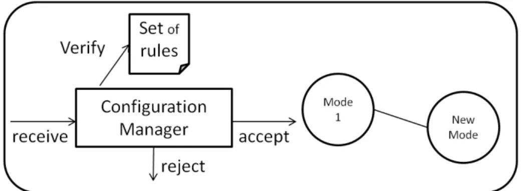
In this class, the evolving environment has unpredictable changes. There are no prede-fined modes or configurations. When the system receives a change operation from the user, the reconfiguration manager should analyze the change request and verify that the request does not break the system consistency or violates the system invariants. If some change operations violates the system consistency or its invariants, then the reconfig-uration manager must reject this change because it will generate inconsistent system. Therefore, a set of invariants in this category of reconfiguration forms a basis for preserv-ing the system consistency.
Figure 2.8 shows a model for an unpredictable reconfigurable system. The unpre-dictable reconfiguration has no predefined modes. Instead, in order to apply the required changes the system can move from a mode (configuration) to a new unplanned mode (new configuration). The reconfiguration manager has a set of rules which represent the system invariants. It receives the commands of change from the user, or from the plan-ning manager (if the system is autonomic). Then it verifies if these change commands do not violate the system invariants. If it discovers any violation, then the command will be rejected. So, the reconfiguration manager here filters and refines the incoming change requests in order to preserve the system consistency and the invariants.
Figure 2.8: shows an unpredictable reconfigurable system model
This approach has various advantages. First, it is very general. Secondly, the systems here are more flexible and adaptable. Finally, the reconfiguration is independent from the system specifications. However, there are some disadvantages also. First preserving the consistency and the structural integrity is a very tedious task. Secondly, executing any incorrect change can destroy the whole system. Therefore, the verification process
should guarantee the preservation of consistency.
2.9
Dynamic Reconfiguration Challenges
2.9.1
Global Consistency
We say that a system has global consistency or integrity when certain constraints about its structure are satisfied [YM92, KM98]. Usually, we express these constraints as facts. a reconfiguration operation is considered as a valid operation if it satisfies the whole set of the integrity constraints. For example, the following list shows some invariants about the system structure:
• In order to preserve the structure of a system based on binary tree architecture, the following invariant should always be satisfied: Each component from the layer
N should at most connect to two components from the layer N − 1.
• Suppose we have a distributed system which has a ring topology and each com-ponent represents a particular node. The essential constraint to preserve the ring topology is: Each component should only connect to exactly two other components, forming a circular pathway.
• A global invariant may be: The number of components in the system should be always less than maxN .
• To prevent the self binding we may express this constraint by the following fact: A component cannot bind to itself. This can prevent the self relation.
The structure integrity constraints represents the system invariants. These invariants should be hold during and after the reconfiguration operating. Violating such constraints can generate inconsistent system, i.e. produce incorrect and unusable system.
2.9.2
Local Consistency
The essential role of dynamic reconfiguration management is to preserve the local consis-tency of the system during and after the change. Dynamic reconfiguration should leave the system in a consistent state. A consistent system is a system which continue its execution after the reconfiguration without falling into error states due to the reconfigu-ration.
The local consistency focus on the following points:
• Preserving the correct interactions between the system components during and after the reconfiguration, so that the system continue its execution in a correct way.