THÈSE
THÈSE
En vue de l’obtention du
DOCTORAT DE L’UNIVERSITÉ DE TOULOUSE
Délivré par : l’Université Toulouse 3 Paul Sabatier (UT3 Paul Sabatier)
Présentée et soutenue le 4 Octobre 2016 par :
Christian VASSALLO
USING HUMAN-INSPIRED MODELS FOR GUIDING ROBOT
LOCOMOTION
JURY
M. PHILIPPEFRAISSE Prof. à l’ Univ. de Montpellier 2 Rapporteur
M. FRANCESCO NORI Tenure Track Researcher IIT Rapporteur
M. PHILIPPESOUÈRES Directeur de Recherche CNRS Membre du Jury
M. OLIVIERSTASSE Directeur de Recherche CNRS Membre du Jury
M. JULIENPETTRÉ Chargé de Recherche INRIA Membre du Jury
École doctorale et spécialité : EDSYS : Robotique 4200046 Unité de Recherche :
Laboratoire d’Analyse et d’Architecture des Systèmes Directeur(s) de Thèse :
M. Philippe SOUÈRES et M. Olivier STASSE Rapporteurs :
A miei genitori Paolo e Giulia, che mi hanno insegnato ad amare. A mio fratello Enrico, che mi ha mostrato come diventare. To Andrea, Nemo and Andreas, because I wouldn’t have done this without them. A Shila, il mio più bel dolce ricordo.
i
Acknowledgement
First of all, I would like to thank Philippe Fraisse and Francesco Nori for reviewing this thesis. I really appreciate your availability and commitment.
I would like to thank the European Commission for founding the project KoroiBot of which this thesis is part. It allowed to have really interesting collaborations with different partners and know new people.
These three years have been the most important and difficult ones of my life. It has been really challenging to leave my country, my family, my friends and start a new life in a foreign place, knowing nobody. I want to thank Francesco Morsillo, who helped me in the first days introducing me to my first "Toulouse family". Luckily, I have found an amazing work team and I want to thank all the members of Gepetto that in these years were always available and funny. In particular, I want to thank Maximilian Naveau because he helped me a lot with French bureaucracy and supported me in bad working time. I gratefully acknowledge my supervisor Philippe Souères. He never stopped to believe in me, even when I was really far from results. He helped me many times, also for my personal problems, and he really showed me one of the best examples of people that I would like to become. Thank you very much Philippe.
I also want to thank Olivier Stasse. He encouraged me so much at the beginning of my thesis, and sometimes I was feeling below his expectations. However, at the end he was happy about my work and I realized that he was just trying to get the best out of me. Thank you Olivier.
I want to express my sincerest gratitude to Julien Pettré, Anne-Hélène Olivier and Armel Crétual. It has been a pleasure to work with them. Our work has been really inten-sive but I have always been greatly motivated by their experience and easygoing approach. In particular, I really appreciated the way they made me feel comfortable when I was in Rennes. It has been really precious and an experience of life. Thank you so much.
A special thank is for my bros Andrea, Andreas, Olivier, Nemo, Nemanja and François. They have been amazing colleagues and friends. They are examples of great people. I shared with them the best memories here in Toulouse and, also, the worst ones. They always have been there for me. They always offered me their shoulders to cry on. Always. I cannot forget this, I will never do. Thank you bros.
Un ringraziamento speciale va alla mia famiglia che, seppur distante, mi è sempre rimasta vicino dall’inizio alla fine. A mia Zia Ro e a mio Zio Chicco, che mi hanno sempre rifornito di cibo e amore ogni volta che tornavo dall’ Italia. Quante volte son tornato tardi da lavoro e un’ottima cena era già pronta grazie a voi. A mia cugina Patrizia, che per ore e ore ha sempre ascoltato i miei problemi al telefono dandomi preziosi consigli. Come potrei dimenticare? Grazie.
A mia madre Giulia e a mio padre Paolo, che non hanno mai smesso di credere in me. È grazie a loro, più di tutti, se sono riuscito a terminare i miei studi. Mi hanno aiutato a crescere, a credere in me, a non mollare e a non perdere la retta via. A mio fratello Enrico, alla piccola Gaia e a Silvia, che mi hanno tenuto compagnia per tutti questi anni da dietro uno schermo, riuscendo a farmi sorridere anche quando non ne avevo proprio voglia.
Thank to everybody that in these years shared with me amazing memories. Thank you Michele, Giulio, Matilde, Giovanni, Roberta, Laura, Mylène, Hager, Justin, Justine and Léa. You have been really important experiences of my life. All of you.
I love to say "My bad time is not still over" and that’s true. But thanks to all these people, I would say that "my bad time" have been so amazing :)
Contents
Introduction 1
1 How humans avoid moving obstacle crossing their way? 17
1.1 Introduction . . . 19
1.2 Minimal Predicted Distance . . . 21
1.3 Materials and Methods . . . 22
Participants . . . 22 Apparatus . . . 23 Participant Task . . . 23 Recorded Data . . . 23 Experimental plan . . . 24 Robot Behavior . . . 24 1.4 Obstacle Control . . . 26 1.5 Analysis . . . 28
Signed Minimal Predicted Distance . . . 28
Kinematic data . . . 28
Statistics . . . 30
1.6 Results . . . 30
1.7 Discussion . . . 35
1.8 Conclusion . . . 36
2 Human and Robot interaction: cooperative strategies for collision avoidance 39 2.1 Introduction . . . 41
2.2 Materials and Methods . . . 43
2.2.1 Participants . . . 43 2.2.2 Apparatus . . . 43 2.2.3 Participant Task . . . 44 2.2.4 Recorded Data . . . 44 2.2.5 Experimental plan . . . 45 2.3 Robot Behavior . . . 45 2.3.1 Passive Behavior . . . 46 2.3.2 Cooperative Behavior . . . 46 2.4 Analysis . . . 47
2.4.1 Kinematic data . . . 47 2.4.2 Statistics . . . 49 2.5 Results . . . 49 2.5.1 Passive Robot . . . 49 2.5.2 Cooperative Robot . . . 53 2.5.3 Crossing Distance . . . 57 2.6 Discussion . . . 57 2.7 Conclusion . . . 58
3 Learning Movement Primitives for the Humanoid Robot HRP2 59 3.1 Introduction . . . 61
3.1.1 Modeling of whole-body movements in computer graphics . . . 61
3.1.2 Biological motor control of multi-step sequences . . . 62
3.1.3 Related approaches in humanoid robotics . . . 62
3.2 System architecture . . . 64
3.2.1 Human data . . . 64
3.2.2 Stack Of Tasks (SoT) . . . 69
3.2.3 Walking Pattern Generator (WPG) with Dynamic Filter . . . 72
3.2.4 Robotics Implementation . . . 73
3.2.5 Overall architecture . . . 74
3.3 Results . . . 75
3.3.1 Real Experiments . . . 75
3.4 Conclusions . . . 77
4 The geometry of confocal curves for passing through a door 79 4.1 Introduction . . . 81
4.2 Problem Statement . . . 84
4.3 Some Basic Geometry Around The Door . . . 85
4.3.1 Elliptic Coordinates . . . 88
4.3.2 Kinematic Model of the vehicle in Elliptic Coordinates . . . 89
4.4 Feedback Control Law in Elliptic Coordinates . . . 90
4.5 The Bundle of circles . . . 92
4.5.1 Bipolar Coordinates . . . 94
4.5.2 Kinematic model of the vehicle in bipolar coordinates . . . 95
4.5.3 A simple strategy to steer the vehicle through the door exploiting the geometric properties of the bundle of circles . . . 95
Contents v
4.6 Feedback Control Law in Bipolar Coordinates . . . 96
4.7 Simulations . . . 98
4.8 Experiments . . . 103
4.8.1 Technical Details . . . 103
4.8.2 Experimental Results . . . 107
4.9 Analysis of FOV limits . . . 108
4.9.1 Control strategy in case of FOV limits . . . 111
4.10 Conclusions . . . 112
Conclusion and Perspectives 113 A Mobile Robot Robulab10 123 A.1 Robulab10 Motion Control . . . 125
A.1.1 The robotic platform . . . 125
A.1.2 Robot Remote Control . . . 126
List of Figures
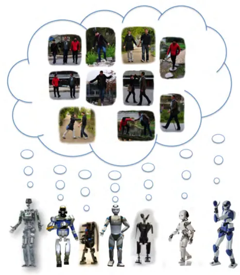
1 Project components of KoroiBot and Interdisciplinary foundations. . . 4 2 The seven humanoid robot platforms of the KoroiBot consortium dreaming
of human walking capabilities. . . 5 3 Challenges of the KoroiBot project. In red the challenges addressed by the
LAAS-CNRS. . . 5 4 Pert chart of the KoroiBot work packages and their interrelationships Our
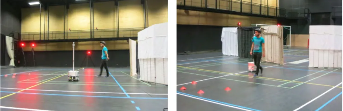
studies concerned WP1 and WP2. . . 6 5 An overview of two different scenarios tested in this study. In the left
pic-ture, two TurtleBots dressed with some papers to make them look bigger. The participant had to walk straight and avoid them. In the right picture, we improved the experimental setup introducing some occluding walls and considering the wheeled robot Robulab that is faster and looks heavier. Each experimental setup, required at least one week of work to be realized and calibrated. . . 8 6 An overview of the experimental setup of the study presented in Chap. 2. . 10 7 An illustrated overview of the work presented in Chap. 3. In the left, an
avatar is reproducing some movements recorded from a human. In the center, an avatar of the humanoid robot HRP-2 is performing the same movements but in a realistic simulation. In the right, a snapshot of real experiments done with the robot HRP-2 at LAAS-CNRS. . . 12 8 An overview of the experimental setup of the work shown in Chap. 4.
The wheeled robot is the same as the one used for the works presented in Chap. 1– 2. The entire work was done at LAAS-CNRS. . . 13 9 Illustration of four different tasks. From top-left to bottom-right: walking
on a soft mattress, walking on a beam, stepping stones, walking stairs up. The kinematic data and the related normal forces are depicted in the smaller images. . . 14 10 (Left) The robot is moving according to the position of the red pylon engine
in order to maintain the same distance (1 meter). (Right) Situation of the experiment: the robot has to go in the vicinity of the pylon engine, depicted in blue, avoiding the red moving toolbox. The robot has to re-plan its path in real-time. In both cases, the robot is tracking the objects using the motion capture system. . . 15
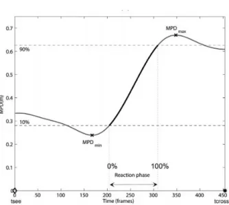
1.1 Illustration of the mpd evolution during the reaction phase between two humans crossing each other [Olivier 2012]. We defined tseeas the instant
of time in which the participant starts to see the other one, and tcrossas the
crossing time. From the picture, we observe that the mpd at tseeis around
0.32m, that means the participants will not collide but they are going to pass near to each other. Once the Reaction phase starts, the mpd is increasing because one of the participants (or perhaps both of them) is reacting to increase the future distance at tcross. In the end of the reaction phase, the
mpd is around 0.7m. . . 22 1.2 a) One of the participants equipped with the full body marker set. b) the
mobile robot Robulab10. . . 23 1.3 Experimental apparatus and task. In this trial the robot was moving from
RSP1 to RSP2. Participant decided to pass behind the robot. . . 24 1.4 Representation of the tracking problem. . . 27 1.5 Example of the analysis of one trial in which a switch of mpd sign occurred.
a) robot and pedestrian trajectories during the trial: triangles and star points are their position at trob and tcross respectively. b) velocity profile of the
walker and the obstacle. c) mpd components. d) mpd evolution during reaction phase (between troband tcross). . . 29
1.6 Example of the analysis of one of PosPos trials. . . 29 1.7 smpd plots for all the 243 trials, after resampling over the interaction time
[trob, tcross]. . . 30
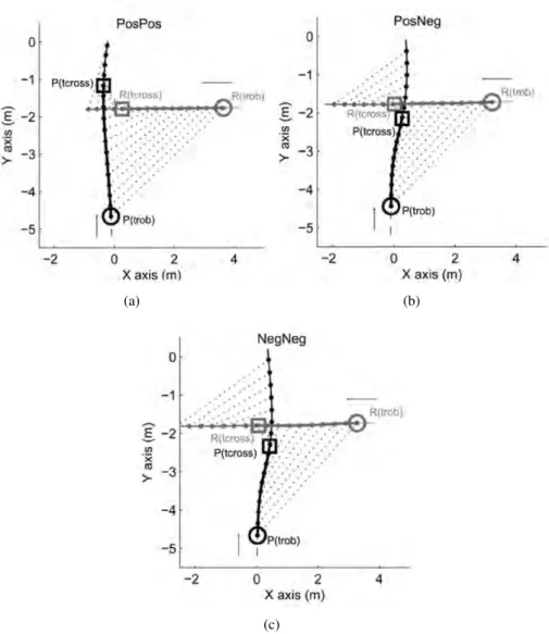
1.8 Three examples of participant-robot trajectories, for PosPos (a), PosNeg (b) and NegNeg (c) category of trial. The part of the trajectory correspond-ing to the interaction [trob, tcross] is bold. Time equivalent
participant-robot positions are linked by dotted line. . . 31 1.9 (a) Mean evolution of smpd for each category of trial ±1 SD. (b) Time
derivative of the mean smpd. . . 32 1.10 a) Comparison between initial and final values of smpd at troband tcross
for all trials of each non-empty category (PosPos, PosNeg, NegNeg). A significant difference in values means that adaptations were made to the trajectory by the participant (**p<0.01, ***p<0.001). b) Comparison be-tween initial and final values of smpd at troband tcross for all the trials of
each subgroup of the PosPos category. c) Total variation for smpd over the interaction. d) Minimum distance observed between the robot and the participant at tcross, with trial grouped by passing order of the participant. . 33
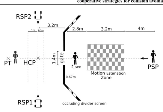
List of Figures ix 2.1 Experimental apparatus and task. The covered area was extended with
respect to the previous work. . . 44 2.2 Experimental setup when robot is cooperative. The pedestrian moves from
PSP to the gate through the MEZ. At 0.67m before crossing the gate, the actor is able to see the robot (tsee). In the following trial, the robot
decel-erates and passes behind the actor, going through VP1. The red robot and the red actor illustrate the hypothetical crossing configuration. . . 47 2.3 (a) smpd>0: The robot starts from RPS1, decelerates and turns right.
(b) smpd<0: the robot starts from RPS1, accelerates and turns left. (b) smpd<0: the robot starts from RPS2, accelerates and turns right. . . 48 2.4 smpd plots for all the 278 trials, after resampling over the interaction time
[trob, tcross]. . . 50
2.5 Examples of participant and robot trajectories for each category of trial. The bold trajectory represents the interaction time [trob, tcross]. . . 51
2.6 Mean evolution of smpd ±1 Standard Deviation for the three categories where the robot is passive. . . 52 2.7 smpd plots for all the 278 trials, after resampling over the interaction time
[tsee, tcross]. . . 54
2.8 Mean evolution of smpd ±1 the Standard Deviation (SD) for the three cat-egories where the robot is cooperative. The category NegPos was not con-sidered. . . 55 2.9 Examples of participant and robot trajectories for each category of trial.
The bold trajectory represents the interaction time [tsee, tcross]. . . 56
3.1 General overview of the system architecture. . . 64 3.2 Illustration of important intermediate postures of the human behavior: step
with initiation of reaching, standing while opening of drawer, and reaching for the object. . . 65 3.3 Predictive planning of real human trajectories. Distances from the pelvis
to the front panel of the drawer (green, yellow and red), and the distance between the front panel and the object (blue) for the ten trials (reproduced from [Mukovskiy 2015a]). (b) The result of the re-targeting process: hu-man avatar and HRP-2 robot during drawer opening task. . . 66 3.4 Extracted source signals. . . 67 3.5 Architecture for the online synthesis of body movements using dynamic
primitives, [Giese 2009a]. This figure represents the module "Kinematic Pattern Synthesis" (see page 74) . . . 68
3.6 Scheme of the feedback loop used to control the humanoid robot HRP-2. [vref, ωref]are respectively the linear and angular velocity and qupperbody the upper body joint trajectories computed from the kinematic pattern syn-thesis. q, ˙q, ¨q are respectively the generalized position and velocity vectors computed using the Stack of Tasks (SoT). . . 74 3.7 (a)Off-line synthesized trajectories generated with the OpenHRP simulator. (b)
The humanoid robot HRP-2 in LAAS-CNRS during the experiments. . . 75
3.8 Forces on the vertical axis (z) measured during the experiment. . . 77 4.1 Objective: to steer a vehicle through a door using only visual measures.
The door is represented by two landmarks, FL and FR and the vehicle,
represented as a directed point, has an on-board camera and is subject to nonholonomic constraints. . . 86 4.2 Elliptic coordinate system. Ellipses and hyperbolae intersect perpendicularly. 87 4.3 For any point Oc= (x, z)there always exists a circle Cα passing through
Ocand the projections in the motion plane of landmarks FLand FR. The
angle at the circumference α is constant along Cα. Notice that, the tangent
and perpendicular line in Octo the hyperbola through Oc, intersect the XW
axis in points A and B, respectively. The segment AB is the diameter of circle Cα. . . 92
4.4 The bipolar coordinate system consists of two orthogonal bundles of cir-cles. Starting from the same point Oc, circle Cα⊥crosses segment FLFR
in a point which is closer to the middle of the door than the one reachable by following the hyperbola through Oc. . . 93
4.5 Function F (τ, ˆα) for different values of ˆα and τ and K = 1. The minimum is at the origin, i.e. at the middle of the door. . . 96 4.6 Vector field obtained as the gradient of F (τ, ˆα) with K = 1. . . 97 4.7 Trajectories of the vehicle starting from the same initial configuration q =
(200, −50, 7π/6), for different values of a in the control law: a = 40 cm (the actual value), a = 80 cm (twice the actual value) and a = 20 cm (half of the actual value). . . 100 4.8 Simulations with the feedback control law in elliptic coordinates:
trajec-tories of the vehicle without and with white Gaussian noise, representing continuous and dashed lines, respectively. The vehicle leaves a room in (a), (b) and enters a room from a corridor (c), by passing through a door. . . 101
List of Figures xi 4.9 Simulations with the feedback control law in bipolar coordinates:
trajec-tories of the vehicle with and without white Gaussian noise, representing continuous and dashed lines, respectively. The vehicle leaves a room in (a), (b) and enters a room from a corridor (c), by passing through a door. . . 102 4.11 Experimental setup. . . 103 4.10 PT7137 camera . . . 103 4.12 Experimental results obtained applying the control law in elliptic
coordi-nates. The control parameters are w = 0.0012, K = 0.7 and λ = 310, an the average linear velocity v = 0.3 m/s. . . 108 4.13 Experimental results obtained applying the control law in bipolar
coordi-nates. The control parameters are K = 2, K1= 4and Kν= 0.15. Average
linear velocity of 0.4 m/s. . . 109 4.14 Analysis of the FOV limits. . . 110 4.15 Some examples of trajectories with the same final orientation, generated by
the control laws in elliptic and bipolar coordinates and by Humans. In (a), (b) and (c) the final orientation is 120 deg. (a) By elliptic coordinates. (b) By bipolar coordinates. (c) By humans (from, [Arechavaleta 2008] cour-tesy of the authors). . . 121 A.1 (a) The basic version of Robulab10 and (b) the one with the Pan–Tilt
List of Tables
1.1 Organization of the trials. . . 25 2.1 Organization of the trials . . . 45 2.2 Statistical analysis results of the smpd data during troband tcrossin the case
that the robot is passive. The Wilcoxon signed-rank test was performed using Statistica v.8 . . . 51 2.3 Statistical analysis results of the smpd data during tseeand tcrossin the case
that the robot is passive. The Wilcoxon signed-rank test was performed using Statistica v.8 . . . 54 A.1 Main technical features of Robulab10. . . 125
3
F
UTURISTIC visions of the world show humans and robots sharing the sameenvi-ronment at different levels of interaction. Fifty years ago the idea that autonomous systems could be active agents in the humans environment was just a dream realizable only in movies. However, in the last decades the scientific community has done huge improvements in this direction and robots are more and more integrated next to humans for supporting them in different kinds of tasks. Recently, the robotics community started to investigate what are the techniques to improve the performances of robots and, in particular, their acceptance in the human society. Probably inspired by the past science fictions, in which the robots had similar appearances and abilities than humans, scientists started to believe that one way to increase robot capabilities was to endorse them with human-like morphological characteristics and behaviors. For these reasons, an increasing number of studies focus on the analysis and the identification of principles, invariants and strategies used by a humans to daily interact with their environments. The development of robots is improved by the progressive evolution of technology, allowing the realization and control of more powerful and complex robots that look more and more like humans. Nowadays the design of humanoid robots, able to help humans and work with them in a real scenario, has became a very important scientific challenge.
The works described in this thesis are directed in such a direction. Assuming that the planning of human movements is optimal, we wanted to study human behaviors during walking tasks. Do we have implicit strategies when we interact with the surrounding environment? Do we act differently each time we have to avoid an obstacle or do we use implicit principles? What are the rules that drive us when we have to walk in a constrained environment like passing through a door? Can we identify and model them? When humans perform a simple action, is it really "simple" or is it made up with hierarchical sequence of sub-tasks? During this thesis we addressed these questions, basing our studies on the analysis of human walking behavior in different situations, with the aim of identifying the invariants of human movements and transfer them to robots.
A large part of the work done in this thesis was done within the framework of the European project KoroiBot. The aim of this project was to improve walking motions of humanoid robots in different scenarios, providing software tools based on mathematical models and methods, in particular optimization, and learning from human data. A more detailed description of the project is provided in the following section.
The European Project KoroiBot
Figure 1: Project components of KoroiBot and Interdisciplinary foundations.
The goal of the KoroiBot project is to enhance the ability of humanoid robots to walk in a dynamic and versatile fashion in the way humans do. Research and innovation work in KoroiBot mainly targets novel motion control methods for existing hardware, but also derives optimized design principles for next generation robots. The new software technolo-gies are based on biological data, with the aim of increasing the performance of humanoid walking. Especially for humanoid robots with redundant degrees of freedom (DoF), opti-mization and learning might be solutions to make the redundancy a benefit rather than a burden. As depicted in Fig. 1, the project methodology can be divided into four pillars: (1) investigation of human walking by experiments, and related extraction of motion prim-itives by mathematical models and identification of walking principles; (2) development of adequate transfer rules; (3) development of novel optimization and learning based control approaches for humanoids walking, (4) integration of these algorithm on several robots (see Fig. 2). In order to test and evaluate the developed software, an interesting scenario consisting of different challenges for the humanoid robots was proposed (Fig. 3).
5
Figure 2: The seven humanoid robot platforms of the KoroiBot consortium dreaming of human walking capabilities.
The work in the KoroiBot context
The European project KoroiBot is an interdisciplinary project. Each partner was assigned to different work packages (WP) focused on particular studies, as shown in Fig. 4. Among these WPs the work that I did during my thesis is related to WP1 and WP2. The former consisted to make different experiments for recording human walking data, aimed at the modeling and the developing of novel motion control laws inspired by biology. The latter targets to synthesize complex actions from sequences of elementary motor tasks and transfer them to the humanoid robots of the consortium.
Figure 4: Pert chart of the KoroiBot work packages and their interrelationships Our studies con-cerned WP1 and WP2.
7
Overview of the thesis
The work presented in this thesis is mainly focused on the analysis of human motion and the identification of human principles that can be transferred to robots for improving their capabilities. The manuscript can be roughly divided in two parts: the first one describes the studies that have been done in the context of the KoroiBot project. The second part presents a collaboration that has been done internally at LAAS-CNRS. The thesis is divided in four main chapters that can be summarized as follows:
ä Chap. 1 and 2 : Identification of walking strategies for avoiding a moving obstacle, ä Chap. 3 : Use of motion primitives to implement complex movements on humanoid
robots,
ä Chap. 4 : Vision-based control to pass through a door.
An overview of each chapter is provided in the following sections.
Chapter 1
Title: How humans avoid moving obstacle crossing their way? Study: Identification of walking strategies for avoiding a moving obstacle Context: KoroiBot project, WP1
Time: during 1stand 2ndyear
Collaborators: INRIA-Rennes, MimeTIC research team and University of Rennes 2, M2S lab
People: Anne-Hélène Olivier, Julien Pettré and Armel Crétual Place: LAAS-CNRS (Toulouse) and Campus de Ker Lann (Rennes) Key Words: Human direct-goal locomotion, Motion Capture System,
Moving obstacle, Collision avoidance strategies, Passive Behavior Summary
One of the first steps of this thesis was to analyze human walking motions during situa-tions which could perturb the natural behavior of a person. With this aim, we decided to make experiments in which a pedestrian, that was walking calmly and naturally, was sig-nificantly disturbed. To this end, we wanted to introduce one or multiple external agents in the scenario, as obstacles, in order to record human reactions in terms of trajectory (speed and turning) and body organization (orientation of the feet, shoulders, head and the step frequency). In order to generate such a situation, the "obstacle" had to move. In particular, as we wanted to create precise and repeatable experiments, we chose to control a wheeled
robot to impersonate the moving obstacle. Having in mind the related works on human locomotion, we found interesting the possibility to collaborate with specialists in this field. So, we started a productive partnership with researchers of INRIA-Rennes who, in their previous studies, had investigated the strategies set by two humans crossing each other or in a crowd scenario. In particular, the main idea was to compare the human strategies that our partners already identified, with the ones set to avoid a moving obstacle. Given their experience in human motion and our knowledge in robot control, we setup interesting ex-periments in which a moving obstacle had to perpendicularly cross the pedestrian path. The control algorithm allowed us to generate specific interactions that aimed to be as similar as possible to the ones observed between two humans. All the experiments took place in the Campus de Ker Lann which provides a huge gymnasium supplied with a motion capture system that perfectly matched our objectives. The recorded human data have been shared and uploaded in the KoroiBot database. After several tests we realized the ideal experimen-tal setup: the robot starting position had to be hidden by some occluding walls otherwise the pedestrians were adapting too early; moreover, the wheeled robot had to be a fast and a robust object in order to perturb significantly the behavior of the participants. To help the reader to figure out the scenarios, an overview of them is shown in Fig. 5. In the following chapter, we will present experiments where the moving obstacle was controlled to behave passively(1). In this way, only the participant contributed to solve the collision.
Figure 5: An overview of two different scenarios tested in this study. In the left picture, two Turtle-Bots dressed with some papers to make them look bigger. The participant had to walk straight and avoid them. In the right picture, we improved the experimental setup introducing some oc-cluding walls and considering the wheeled robot Robulab that is faster and looks heavier. Each experimental setup, required at least one week of work to be realized and calibrated.
Passive Behavior (1)
In this manuscript we use the term "Passive Behavior" to indicate that the robot was controlled to move straight and at constant speed. The robot was not reacting to the adaptations performed by the participants.
9
Chapter 2
Title: Human and Robot interaction:
cooperative strategies for collision avoidance.
Study: Identification of walking strategies for avoiding a moving obstacle Context: KoroiBot project, WP1
Time: during 3rdyear
Collaborators: INRIA-Rennes, MimeTIC research team and University of Rennes 2, M2S lab
People: Anne-Hélène Olivier, Julien Pettré and Armel Crétual Place: LAAS-CNRS (Toulouse) and Campus de Ker Lann (Rennes) Key Words: Human direct-goal locomotion, Motion Capture System,
Moving obstacle, Collision avoidance strategies, Reactive Behavior Summary
Nowadays, the robotics community is putting a lot of effort on the development of robots that can perform tasks like humans and improve their capabilities in terms of energy consumption and precision. Clearly, in the future robots and humans will share the same spaces and they will have to adapt each others. Although humans adjust their behavior according the surrounding environment quite spontaneously, such a task is not trivial for robots. Moreover, ideally the movements of the robot should be optimized in order to make humans adapt more naturally. In this context, the study presented in this chapter is more based on the social aspects of human behavior. We believe that, in order to improve robot locomotion capabilities, it is important to analyze also the psychological aspects of the human behavior and not only the kinematic ones. In other word, we hypothesize that it is necessary to understand the rules behind the human strategies before transferring them. This could even help to simplify the modeling and the integration of human principles in complex systems as humanoid robots. Daily, walkers avoid each others in several different situations but they succeed such a task more or less in a similar way. We arose question like: are these strategies implicit? Can we define and transfer them? Can we optimize the way robots interact with humans? Can we make a walker behave more naturally in an environment in which there are autonomous system moving around him? This study aims to address these questions.
In the last year of this thesis, we decided to continue the previous collaboration with our partners of INRIA-Rennes. As already explained, in the previous experiments we controlled the robot to behave passively. However, we were interested to extend this work,
by controlling the robot in a more unpredictable way to perturb more considerably the innate walking of the pedestrians. To this end, in this second part we controlled the robot to behave reactively(2). We transferred the collision avoidance strategies observed in
humans to the robot and we analyzed the human reactions. The main idea was to study the differences with respect to the case in which the robot behaves passively. Moreover, we wanted also to compare the avoidance strategies of the participants, in the case that the robot acts like a human, with respect to the ones observed between two pedestrians [Olivier 2013]. We reproduced the same experimental setup of the Chap. 1, improving the quality and the design of the experiments. We used the same robot platform. An overview of the scenario is shown in Fig. 6.
Figure 6:An overview of the experimental setup of the study presented in Chap. 2.
Reactive Behavior (2)
In this manuscript we use the term "Reactive Behavior" (or "Active Behavior") to indicate that the robot was controlled to positively contribute to the collision avoidance. In reactive mode, the robot predict human movements and it adapts its velocity and orientation in order to avoid the collision.
11
Chapter 3
Title: Learning Movement Primitives for the Humanoid Robot HRP-2 Study: Use of motion primitives to implement complex movements
on humanoid robots Context: KoroiBot project, WP2 Time: during 2ndand 3rdyear
Partners: University Clinic Tübingen, Department of Cognitive Neurology People: Albert Mukovskiy, Martin A. Giese
Place: LAAS-CNRS (Toulouse)
Key Words: Robotics, Goal-directed walking, Motion primitives,
Walking pattern generator, Motor coordination, Action sequences Humanoid robots are complex and redundant mechanical systems. One of the robotics community challenges is to create humanoid robots equipped with human features i.e. communication skills, walking capabilities, adaptation and reactive movements. However, humans and humanoid robots are really different in terms of size, geometrical proportions, velocity and acceleration limits, power and energy consumption. Human abilities are learned and improved by life experience and they are further improved everyday. For this reason, it is really challenging to find the way to transfer such advanced human capabilities to robots. However, recent studies on human motion have shown that complex actions can be represented as a sequence of motor primitives(3) [Flash 2005].
These motion primitives are hypothesized as being the "building bricks" of any action. Therefore, the main idea is that instead of analyzing and trying to reproduce human full-body complex motion, one should identify the "alphabet" of movements used by the brain. In other words, assuming that an alphabet of movements is known, it could be possible to compose any kind of complex movements as a sequence of contribution of simple letters that are the motion primitives.
In the framework of the KoroiBot project, the WP2 proposed to integrate complex motion strategies into locomotion control as simple sequences of individual steps or step phases, which mimic optimal behavior of humans. Based on some extracted primitives, techniques as machine learning and optimal control should be used to derive models and data, and transfer them to humanoid robots. In this context, we decided to consider walking-to-grasp movements and implement them on the humanoid robot HRP-2 at LAAS-CNRS.
In this chapter we will present a novel highly flexible approach to model complex movements based on an hierarchical use of motion primitives. These primitives can be combined in space and time and over multiple temporal scales. They are learned by bio-logical kinematic data and then reformulated in a mathematical framework which allows their implementation in optimal control systems. The methods we used for learning the motion primitives are based on previous works done by our partners from Tübingen. They allow to decompose complex movements in terms of motion primitives, based on kinematic data [Giese 2009b, Mukovskiy 2013]. In this context, we proposed a whole body controller in which the upper-body movements are generated by a combination of such motion prim-itives whereas the lower body behavior is computed by a walking pattern generator.
Figure 7: An illustrated overview of the work presented in Chap. 3. In the left, an avatar
is reproducing some movements recorded from a human. In the center, an avatar of the humanoid robot HRP-2 is performing the same movements but in a realistic simulation. In the right, a snapshot of real experiments done with the robot HRP-2 at LAAS-CNRS.
Motion Primitives(3)
"Motion Primitives" (or "Motor Primitives") refer roughly to building blocks at different levels of the motor hierarchy. They do need to be universal and the same building block is not necessarily used for all the possible behaviors or tasks. Instead, they might be specific to only a particular representation of movements or tasks. The crucial feature is that many different movements can be derived from a limited number of motor primitives through appropriate operations and transformations, and that these movements can be combined through a well defined syntax of motion to generate more complex actions. An exhausting description of Motion Primitives, at different levels (behavioral, neural, muscle, kinematic and dynamic), has been provided by Tamara Flash [Flash 2005]
13
Chapter 4
Title: The geometry of confocal curves for passing through a door Study: Vision-based control to pass through a door
Context: Internal collaboration (LAAS-CNRS) Time: during 1st and 2ndyear
Collaborator: ERC Actanthrope
People: Paolo Salaris, Jean-Paul Laumond Place: LAAS-CNRS (Toulouse)
Key Words: Nonholonomic motion planning, Visual servoing, Wheeled robots From the experience gained and the software developed to control a wheeled robot as a moving obstacle, we developed an internal collaboration at LAAS-CNRS within the frame-work of ERC Actanthrope. The aim of this frame-work was to implement some vision-based control laws to steer a robot through a door by using advanced geometric parametriza-tion provided by confocal curves. At the beginning we planned to implement this control on HRP-2, however given the difficulties to obtain accurate vision-based controls during walking on humanoid robots, we decided to initially test the algorithm into a nonholonomic wheeled robot equipped with a rigidly pinhole camera. We developed and implement con-trol strategies to detect a door, identified by two landmarks attached to its vertical supports, and steer the vehicle to pass through it. We built around the door a planar geometry of bundles of hyperbolas, ellipses and orthogonal circles. The method is able to drive the robot to the goal by using static feedback control laws that are function of the current state of the system expressed in suitable coordinates. The originality of this work is that these new coordinates can be directly measured in the camera plane. Although the methods was implemented on a wheeled robot and not an anthropomorphic system, we found that the proposed approach had similarities with the strategy adopted by humans for passing through a door. An overview of the experimental setup is depicted in Fig. 8.
FR FL Robulab 10 On-board camera Robulab 10 Door Door FR FL On-board camera
From behind the door
Figure 8: An overview of the experimental setup of the work shown in Chap. 4. The wheeled robot is the same as the one used for the works presented in Chap. 1– 2. The entire work was done at LAAS-CNRS.
Other contributions
During the three years of my thesis I also had some other minor contributions. They are rapidly described in this introduction but not further developed in the manuscript.
Recording human motion in the KoroiBot scenario
In the context of the Koroibot WP1, we participated with our project partners from University of Tübingen and University of Heidelberg to experiments for recording human movements in the KoroiBot scenario previously shown in Fig. 3. In all the experiments the body kinematics was recorded with 10 Vicon-MX cameras and the normal forces under the feed was collected with Pedar System. The participants were told to perform the following tasks: walking straight, walking stairs up and down forwards, walking on a soft mattress, walking on a beam forwards, walking on different slopes fast up and down, stepping stones with two different configurations, walking following a circular trajectory at different speed. An overview of the experiments is shown in the pictures above. An illustration of some experiments is provided in Fig. 9.
Figure 9: Illustration of four different tasks. From top-left to bottom-right: walking on a soft mattress, walking on a beam, stepping stones, walking stairs up. The kinematic data and the related normal forces are depicted in the smaller images.
15 A new tool for tracking HRP-2 with the motion capture system of LAAS-CNRS Another minor contribution during this thesis has been done at the beginning of the first year. Supported by Airbus/Future of Aircraft Factory and CNRS, we presented a prelim-inary proof of concept aiming at introducing humanoid robots in an aircraft factory. The goal was to demonstrate the capabilities of HRP-2 to deal with three aspects needed in a factory: reactivity to the changes of the environment, visual feedback and on-line motion generation. In particular, the robot had to move from a random starting position to a prede-fined target, while avoiding a moving obstacle crossing its way (respectively the red pylon engine depicted in blue and the red moving toolbox in Fig. 10). In order to localize the position of the robot, the obstacle and the target in the environment, each of them were equipped with markers and tracked by a motion capture system (MoCap) in the area. My contribution was to find the transformation matrix that links the HRP-2 joint frames and the MoCap system. In other words, we determined a tool to express the position and the orientation of each joint frame of HRP-2 in the MoCap frame. Thanks to this tool, that it is still currently used, we have been able to make improvements for our laboratory setup. For example, it has been possible to implement an algorithm into the crane control system for an automatic tracking and following of the robot during the experiments in the area. Moreover, we used this tool also for the benchmark of KoroiBot. Through motion cap-ture system, we evaluate the precision and the improvement of HRP-2 walking controls, comparing the expected configurations and the real ones in different trials of walking.
Figure 10: (Left) The robot is moving according to the position of the red pylon engine in order to maintain the same distance (1 meter). (Right) Situation of the experiment: the robot has to go in the vicinity of the pylon engine, depicted in blue, avoiding the red moving toolbox. The robot has to re-plan its path in real-time. In both cases, the robot is tracking the objects using the motion capture system.
Publications
Journal
Accepted
n C. Vassallo, AH. Olivier, P. Souères, A. Crétual, O. Stasse et Pettré J. How do walkers
avoid a mobile robot crossing their way? Gate and Posture, vol. 51, pages 97 – 103, 2017
n P. Salaris, C. Vassallo, P. Souères et JP. Laumond. The geometry of confocal curves
for passing through a door. IEEE Transactions on Robotics, vol. 31, no. 5, pages 1180–1193, 2015
Under review
n A. Mukovskiy, C. Vassallo, M. Naveau, O. Stasse, P. Souères et MA. Giese.
Adap-tive synthesis of dynamically feasible full-body movements for the Humanoid Robot HRP-2 by flexible combination of learned dynamic movement primitives. Robotics and Autonomous Systems, 2016. Corrected version under review
Conference
Accepted
n P. Salaris, C. Vassallo, P. Souères et J-P. Laumond. Image-based control relying
on conic curves foliation for passing through a gate. In 2015 IEEE International Conference on Robotics and Automation (ICRA), pages 684–690. IEEE, 2015
n O. Stasse, F. Morsillo, M. Geisert, N. Mansard, M. Naveau et C. Vassallo.
Air-bus/future of aircraft factory HRP-2 as universal worker proof of concept. In 2014 IEEE-RAS International Conference on Humanoid Robots, pages 1014–1015. IEEE, 2014
n A Mukovskiy, C. Vassallo, M. Naveau, O. Stasse, P. Souères et Giese MA. Learning
Movement Primitives for the Humanoid Robot HRP-2. In IEEE IROS 2015 Work-shop on "Towards truly human-like bipedal locomotion: the role of optimization, learning and motor primitives". Hamburg, Germany, 2015
C
HAPTER1
How humans avoid moving obstacle
crossing their way?
1.1. Introduction 19 The work presented in this chapter was done in collaboration with biomechanists of the MimeTIC research team of Inria Rennes (French National Institute of Research in Computer Science and Control) and the "Movement, Sport and health Science" labora-tory (M2S) in Rennes. A shorter description of this work can be found in [Vassallo 2017]. The aim of this collaboration was to analyze the human strategies to avoid collision with a moving obstacle. Having in mind previous results on human obstacle avoidance, as well as the main principles that they use for collision avoidance, we observe how humans adapt a goal-directed locomotion task when they have to interfere with a non collaborative mo-bile robot. Our results show differences in the strategy set by humans to avoid a robot in comparison with avoiding another human. The analysis is based on the concept of the risk of future collision distance estimated by the Minimal Predicted Distance, denoted by mpd [Olivier 2012]. mpd gives, for each time step, the future distance of closest approach be-tween the human and the robot if both of them keep a constant speed and direction. Since the robot is controlled to move straight and at constant velocity, only the human walker is actively reacting to ensure collision avoidance. As an extension of this work, in the next chapter (Chap. 2), we will present experiments in which the robot is adapting its behavior to positively contribute to the collision avoidance.
1.1 Introduction
Robots and humans will share the same environment in a near future [Goodrich 2007, Kruse 2013]. To this end, roboticists must guarantee safe interactions between robots and humans during locomotion tasks. Our work goes a step further in this direction by studying how humans behave to avoid a moving robot.
There is an extensive literature describing how walkers avoid collisions. Several studies considered how walkers step over [Patla 2006] or circumvent [Vallis 2003] static obstacles. More recent ones focused on how humans avoid each other. It was shown that walkers are able to predict the risk of collision since they adapt their motion only if the future crossing distance is below a certain threshold [Olivier 2012]. This future distance is increased ahead of the crossing point and maintained constant during a regulation phase, demonstrating anticipation in avoidance [Olivier 2012]. Trajectory adaptations are performed both in speed and orientation [Huber 2014, Olivier 2012]: they depend on the crossing angle and the walking speed [Huber 2014]. These strategies do not maximize smoothness [Basili 2013], they result from a compromise between safety guarantee and energy minimization [Jansen 2011]. Moreover, these adaptations depend more on situations than personal characteristics [Knorr 2016].
The crossing order during collision avoidance is an interesting parameter to con-sider. Indeed, it has been shown that trajectory adaptations are collaboratively performed [Olivier 2012] but are role-dependent. The walker giving way (2nd at the crossing) con-tributes more than the one passing first. This role attribution appears to contribute pos-itively before the interaction [Knorr 2016, Olivier 2013] and can be predicted with 95% confidence at almost 2.5m before crossing, even before any adaptation [Knorr 2016].
Studies resulted into simulation models of navigation and interaction. Warren and Fa-jen [Warren 2008] proposed to model the walker and the environment as coupled dynamical systems: the walker paths result from all the forces acting on them, where goals are consid-ered as attractors and obstacles as repellors. This model is based on the distance to the goal and to the obstacles as well as the sign of change of the bearing angle. An integration of the bearing angle theory into some artificial vision system for crowd simulation was proposed by Ondrej et al. [Ondrej 2010].
These previous studies reached common conclusions about the human ability to accurately estimate the situation (crossing order, risk of collision, adaptations), and considered interactions with a moving objects. The kinematics of adaptations by a walker avoiding a moving obstacle (a mannequin mounted on a rail) are studied in [Cinelli 2007, Cinelli 2008, Gérin-Lajoie 2005]. Trajectories crossing at 45◦ resulted into
adaptations both in the antero-posterior and medio-lateral planes, with successive anticipa-tion and clearance phases [Gérin-Lajoie 2005]. Analysis is based on the noanticipa-tion of personal space modeled as a free elliptic area around each walker. When trajectories are colinear (the mannequin comes from the front), a 2-step avoidance strategy is observed: participants first adapt their locomotion in heading, then by speed [Cinelli 2008]. Moreover, the obsta-cle velocity influences the lateral rate of change of the walker trajectory [Cinelli 2007]; the slower the velocity, the lower the lateral rate of change. These experiments with man-nequins were not designed to study the question of the crossing order. Other studies in-vestigated human interactions with robots. It was shown that it is easier to understand and predict the behavior of robots if they are human-like [Carton 2013, Lichtenthäler 2013]. Some studies demonstrated that human-like behaviors [Dragan 2015, Kato 2015] improve on many levels the performance of human-robot collaboration. Nevertheless, the benefit of programming a robot with human-like capabilities to move and avoid collision with a human walker has not been demonstrated yet.
The chapter is structured as follows. Firstly, we recall the meaning of Minimal Pre-dicted Distance. Then we present our approach in which a moving robot has to interfere with a pedestrian. The experimental setup is detailed in Section 1.3. In Section 1.4 we show how to control the robot to reproduce similar kinematic condition of interaction than the ones studied in [Olivier 2012] (in terms of relative angle, position, and velocities) and
1.2. Minimal Predicted Distance 21 we apply a similar analysis in Section 1.5. While the nature of the interaction is changed, our results show differences in the strategy set by humans to avoid a robot in comparison with avoiding another human (Section 1.6 and Section 1.7). Finally we will see in Sec-tion 1.8 how humans prefer to give the way to the robot even when they are likely to pass first at the beginning of the interaction.
1.2 Minimal Predicted Distance
As explained before, the crossing configuration and the risk of future collision were esti-mated by the Minimal Predicted Distance, noted mpd [Olivier 2012]. In other world, the mpd functions provides information about the risk of collision: the smaller the mpd, the higher the risk of collision. For each time step, its value correspond to the future distance of closest approach if both the robot and the participant keep a constant speed and direction. Thus, as the robot is moving straight at constant speed (in the time phase of the experi-ments which are presented in this chapter), a variation of mpd means that the participant is performing adaptations. In other words, collision avoidance could be analyzed with respect to the variation of speed v and the orientation θ during the reaction phase (see Figure 1.1). In order to identify what were the main adaptations (accelerating/decelerating or turning), we partially derived the mpd function. Indeed, denoting by θ1 and s1 the instantaneous
orientation and speed of participant #1 (θ2and s2 for #2 respectively) and X = (a,b) the
relative position of participant #2 with respect to #1, the mpd turns on to be a function of all these variables:
mpd = f (a, b, θ1, s1, θ2, s2) (1.1)
For any of the 6 parameters ∈ {a,b,θ1, s1, θ2, s2}, the instantaneous individual effect of p,
in the mpd, can be expressed by the following partial derivative: εp=
∂mpd ∂p · dp =
∂f
∂p· dp (1.2)
The total instantaneous effect 5f of the 6 parameters is then:
5 f = εa+ εb+ εθ1+ εθ2+ εv1+ εv2 (1.3) As an extension of the previous works [Olivier 2012, Olivier 2013], we introduced a signed definition of the mpd, noted smpd. The sign of this function depends on who, among the human and the robot, is likely to pass first or give way to the other participant. Further details will be treated in Section 1.5.
Figure 1.1: Illustration of the mpd evolution during the reaction phase between two humans
cross-ing each other [Olivier 2012]. We defined tseeas the instant of time in which the participant starts
to see the other one, and tcrossas the crossing time. From the picture, we observe that the mpd at
tseeis around 0.32m, that means the participants will not collide but they are going to pass near to
each other. Once the Reaction phase starts, the mpd is increasing because one of the participants
(or perhaps both of them) is reacting to increase the future distance at tcross. In the end of the
reaction phase, the mpd is around 0.7m.
1.3 Materials and Methods
Participants
Seven volunteers participated in the experiment (1 woman and 6 men). They were 26.1 (± 5.4) years old and 1.78m tall (±0.21). They had no known vestibular, neurological or muscular pathology that would affect their locomotion. All of them had normal or corrected sight and hearing. Participants gave written and informed consent before their inclusion in the study. The experiments respect the standards of the Declaration of Helsinki (rev. 2013), with formal approval of the ethics evaluation committee Comitè d’Evaluation Ethique de l’Inserm (IRB00003888, Opinion number 13-124) of the Institut National de la Santé et de la Recherche Médicale, INSERM, Paris, France (IORG0003254, FWA00005831). All the participants were equipped with a full body marker set (53 markers) (see Figure 1.2a). They were located following the standard marker placement of Koroibot project1.
1.3. Materials and Methods 23
Figure 1.2: a) One of the participants equipped with the full body marker set. b) the mobile robot Robulab10.
Apparatus
The experiment took place in 50m x 25m gymnasium. The room was separated in two areas by 2m high occluding walls forming a gate in the middle. An overview of the experimental setup is shown in Figure 1.3. Four specific positions were identified: the participant starting position PSP, the participant target PT, and two robot starting positions RSP1 and RSP2. A specific zone between PSP and the gate is named Motion Estimation Zone MEZ. MEZ is far enough from PSP for the participants to reach their comfort velocity before entering the MEZ. The intersection point of the robot path [RSP1, RSP2] and the participant path [PSP, PT] is named Hypothetical Crossing Point HCP. It is computed hypothesizing that there is no adaptation of the participant trajectory.
Participant Task
Participants were asked to walk at their preferred speed from PSP to PT by passing through the gate. They were told that an obstacle will be moving over the gate and could interfere with them. One experimental trial corresponds to one travel from PSP to PT.
Recorded Data
3D kinematic data were recorded using the motion capture Vicon-MX system (120Hz). Reconstruction was performed using Vicon-Blade and computations using Matlab (Math-works r). The experimental area was covered by 15 infrared cameras. The global position of participants was estimated as the middle point of reflective markers set on the shoulders
Figure 1.3: Experimental apparatus and task. In this trial the robot was moving from RSP1 to RSP2. Participant decided to pass behind the robot.
(acromion anatomical landmark, LSHO-RSHO). The stepping oscillations were filtered out by applying a Butterworth low-pass filter (2nd order, dual pass, 0.5Hz cut-off frequency).
Experimental plan
Each participant performed 40 trials (see Table 1.1). Robot starting position (50% in RSP1, 50% in RSP2) was randomized among the trials. To introduce a bit of variability, in 4 trials the robot did not move and the participant did not have to react. Only the 36 trials with potential interaction were analyzed.
Robot Behavior
We used a prototype of RobuLAB10 wheeled robot from the Robosoft company (dimen-sion: 0.45 x 0.40 x 1.42m, weight 25 Kg, maximal speed around 3 m/s) (see Figure 1.2b). The robot position was detected as the center point in its base (more details are given in
1.3. Materials and Methods 25
Table 1.1: Organization of the trials.
Trial Robot Moving RSP MPD Trial Robot Moving RSP SMPD
1 Yes Right 0.8 21 Yes Left -0.1
2 Yes Left 0.8 22 No Left – –
3 Yes Right 0 23 Yes Right 0.1
4 Yes Right 0.1 24 Yes Left 0.1
5 Yes Right 1.2 25 Yes Left -0.8
6 No Right – – 26 Yes Left 1.2
7 Yes Left 0.1 27 Yes Left -0.3
8 No Right – – 28 Yes Left 1.2
9 Yes Right -0.3 29 Yes Right 0.8
10 Yes Left 0.3 30 Yes Right 0.3
11 Yes Left -0.3 31 Yes Right -0.1
12 Yes Left 0 32 Yes Left 0
13 Yes Left 0.8 33 Yes Left -0.1
14 Yes Right 0 34 Yes Right 1.2
15 Yes Left -1.2 35 Yes Right 0.3
16 Yes Left -1.2 36 Yes Left 0.3
17 Yes Right -1.2 37 Yes Left -0.8
18 No Left – – 38 Yes Right -0.8
19 Yes Right -0.8 39 Yes Right -0.1
20 Yes Right -0.3 40 Yes Right -1.2
Section 1.4). We programmed the robot to execute a straight trajectory between RSP1 and RSP2 at constant speed (1.4 m/s). The robot was controlled to generate specific interac-tions with the participant. In particular, the robot was either: a) on a full collision course (reach HCP at the same time than the participant), b) on a partial collision course (the robot reaches HCP slightly before or after the participant), or c) not on a collision course. To this end, we measured the participants speed through MEZ and estimated the time thcpat which
HCP was reached. We deduced the time trsat which the robot should start to reach HCP at
thcp. We finally added an offset 4t to trsin order to obtain the desired interactions based
on mpd values selected from the range [-1.2m, 1.2m]. Although the sequence of interac-tions was pre-defined in the remote control station (see Table 1.1), the participants were unaware about it. Each trial was repeated twice.
At the beginning of each trial, the software read the respective line of the table above. The robot starting position was initialized based on the robot velocity (set as constant) and the walker speed. To estimate the latter we used a Kalman Filter, modeling the walker as a material point moving along a line at constant speed (no acceleration). Tests have shown that participant velocity was almost constant in MEZ, then such an approximation was sufficient to reliably estimate the gait speed.
1.4 Obstacle Control
The robot position was tracked using a Vicon motion capture system. The robot position was computed as the centroid of seven markers fixed on its base. The remote control station was an external computer, communicating with the robot platform and the motion capture software through Wi-Fi. The exchange of data between the control station and the Vicon system was established by the ROS Hydro package vicon_bridge2 which contains
the driver needed for the communication. The robot was controlled by the remote station though an UDP connection. Further details about the low-level control of the robot Robulab are provided in Appendix A.
An overview of the experiment was shown in the previous section. The participant had to walk straight, from PSP to PT, pass through the gate and avoid a moving obstacle. The middleware ROS Hydro was used to interface the robot with the motion capture system and the remote control station. In order to guarantee accuracy and reliability of the experiments, a virtual robot with reference behavior was defined to plan the collision. Since obstacle velocity was set as constant (1.4 m/s), the initial position of the virtual robot changed according to the walker gait speed. In other words, the mobile obstacle was controlled in order to follow precisely the behavior of a virtual robot designed to obtain the desired crossing situation. Tracking control was considered for this task.
A right-handed reference frame W with origin in Ow and axes Xw and Yw is attached
to the plane of the robot motion. The configuration of the vehicle is described by q(t) = (x(t), y(t), θ(t)), where (x(t),y(t)) is the position in W of a reference point of the vehicle and θ(t) is the orientation with respect to Xw. Denoting by v(t) and ω(t) the forward and
angular velocities, the kinematics is:
˙ x ˙ y ˙ θ = cosθ 0 sinθ 0 0 1 v ω (1.4)
The tracking problem, under the assumption that the robot velocity never vanishes, is to find a feedback control law such that the configuration q(t) of the real robot matches the one qr(t)of the virtual robot. The error e(t) = q(t) − qr(t)can be written as:
e = e1 e2 e3 = cosθ sinθ 0 −sinθ cosθ 0 0 0 1 xr− x yr− y θr− θ (1.5) 2http : //wiki.ros.org/vicon_bridge
1.4. Obstacle Control 27
Figure 1.4: Representation of the tracking problem.
In [Zheng 1994] the authors have proposed the follows change of inputs u1= −v + vrcos e3
u2= ωr− ω
and proved that the following nonlinear feedbacks make the error q(t) − qr(t)converge to
zero u1= −k1(vr, ωr)e1 u2= −k4vr sin e3 e3 e2− k3(vr, ωr)e3
where k4 is a positive constant and k1, k3 are continuous functions of vr and ωr, strictly
positive. The starting point of the virtual robot changed according to the gait speed of the actor. Considering s as the distance between RSP and HCP, and vgas the average walking
speed of the participant, it is possible to determine the time needed by the walker to reach HCP (tcross). Defining this interval as Time To Contact TTC, we obtain:
T T C =s + mpd vg
(1.6) Since the robot needs time to reach a constant velocity, it was starting to move before the participant crossed the gate. In this way, the obstacle was perceived to move at constant speed. In order to guarantee that the tracking was feasible, the following condition needed to be satisfied: if the virtual robot was slightly ahead to the real one, the latter started to follow the former. Without this control, the real robot was moving backward. However, a considerable acceleration was required at the beginning to quickly minimize the error components e1and e2.
1.5 Analysis
Signed Minimal Predicted Distance
As an extension of the previous works [Olivier 2012, Olivier 2013], we introduced a signed definition of the mpd, noted smpd. The sign of this function depends on who, among the participant and the robot, is likely to reach HCP first (still assuming constant motion). smpd is positive if the participant should arrive first or negative otherwise. A change of sign of smpd means that the future crossing order between the robot and the participant is switched. Our study focuses on the section of data when adaptations are performed: smpd is normalized in time by resampling the function at 100 intervals between trob(time
0%) and tcross (time 100%). Quantity of adaptation is computed as the absolute value of the difference between smpd(trob) and smpd(tcross). This extension was needed because it
was observed that in human-human interaction the participants were always respecting the crossing order and no switch of mpd sign occurred.
Kinematic data
For each trial we computed trob, the time at which the robot reaches its constant cruise
speed (when the acceleration amplitude was below a fixed threshold, 0.003 m/s2), and
tcross, the time of closest approach between the participant and the robot. We decided to
consider trob instead of tsee(the instant of time in which the participant crossed the gate)
because of the robot did not reach its steady state velocity at tseeyet. Such a variation of
velocity influenced too much the initial value of mpd, entailing wrong results. An exam-ple of the kinematic data for one of the trials is shown in Figure 1.5. By combining the trajectories shown in Figure 1.5a and the velocity profiles in Figure 1.5b, it is possible to deduce that the participant decided to decelerate and turn left, giving way to the robot. This hypothesis is confirmed by Figure 1.5c in which the mpd components gave us information about the main strategy adopted. Since the robot is moving straight at constant velocity, its components are almost equal to zero (no contribution). Analyzing the pedestrian ones, we deduce that the pedestrian mainly solves the collision by firstly decelerating (velocity component), then turning. From Figure 1.5d, we can conclude that the participant was slightly in advance with respect to the obstacle (smpd(ttrob)= 0.12), however he decided
to decelerate and after turning to give way to the robot and pass behind with a distance of 0.49 meter (smpd(tcross) w -0.48). The hypothetical smpd was 0.1. Another example of
the kinematic data is reported in Figure 1.6. In this trial, the actor is in advance with re-spect to the robot. Indeed, smpd at time tcrossis 0.78m (hypothetical smpd equal to 0.8m).
1.5. Analysis 29
Figure 1.5: Example of the analysis of one trial in which a switch of mpd sign occurred. a) robot
and pedestrian trajectories during the trial: triangles and star points are their position at troband
tcrossrespectively. b) velocity profile of the walker and the obstacle. c) mpd components. d) mpd
evolution during reaction phase (between troband tcross).
in front of the robot. Although the participant is sufficiently in advance to keep constant his strategy, he decided to accelerate and slightly turn in order to increase the crossing distance to 0.96m. In almost all the trials PosPos in which smpd(tcross) is lesser than one meter, we
observed such kind of reaction to increase the future distance. This aspect will be further analyzed in the discussion section.
Statistics
Statistics were performed using Statistica (Statsoft r). All effects were reported at p<0.05. Normality was assessed using a Kolmogorov-Smirnov test. Depending on the normality, values are expressed as median (M) or mean ± SD. Wilcoxon signed-rank tests were used to determine differences between values of mpd at trob and tcross. The influence of the
crossing order evolution on the smpd values was assessed using a Kruskal-Wallis test with post hoc Mann-Whitney tests for which a Bonferroni correction was applied: all effects are reported at a 0.016 level of significance (0.05/3). Finally, we used a Mann-Whitney test to compare the crossing distance depending on the final crossing order.
1.6 Results
We considered 243 trials because 9 of the 252 were removed, as the robot failed to start. Figure 1.7 depicts the evolution of smpd for all trials. The sign of smpd at tcross shows
that the participants passed first in 42% of all the trials, they gave way in the 58% of other
1.6. Results 31 cases. Combining this information with the sign of smpd at trob(beginning of interaction),
we could evaluate if participants switched their role during interaction, i.e., change the crossing order. We divided trials into four categories depending on the sign of smpd at trob
and at tcross: PosPos, NegNeg, PosNeg and NegPos. For example, the PosNeg category is
for trials with smpd(trob)>0 and smpd(tcross)<0.
All the trials are distributed among those categories in the following way: PosPos=104 trials (43%), NegNeg=69 trials (28%), PosNeg=70 trials (29%), NegPos=0 trials (0%). Ex-amples of corresponding trajectories for each category are illustrated in Figure 1.8. In 29% of cases, participants were likely to pass first at the crossing point but adapted their
trajec-(a) (b)
(c)
Figure 1.8: Three examples of participant-robot trajectories, for PosPos (a), PosNeg (b) and
Neg-Neg (c) category of trial. The part of the trajectory corresponding to the interaction [trob, tcross]
tory to finally give way to the robot. However, the opposite case for which the participant would be likely to give way and finally would pass first was never observed. The mean evolution of smpd in each category is shown in Figure 1.9a and its time derivative in Fig-ure 1.9b. From these curves we can distinguish the reaction period from the regulation one as defined by [Olivier 2012]. They respectively correspond to periods during which partic-ipants perform adaptations (smpd varies) or consider collision to be avoided (the derivative
Figure 1.9: (a) Mean evolution of smpd for each category of trial ±1 SD. (b) Time derivative of the mean smpd.
1.6. Results 33 is null, and may even variate in the opposite direction).
Figure 1.10 shows comparisons between smpd(trob) and smpd(tcross), as well as
dis-tances of closest approach with respect to each of the three non-empty categories, and the crossing distance depending on the crossing order.
PosPos Trials
Difference between smpd at trob (1.05m) and at tcross (1.04m) is at the limit of
signif-icance (p=0.052) (cf Figure 1.10-a). Participants performed no or few adaptations to their trajectory. We detail this result by ordering PosPos trials by increasing smpd(trob)
value and dividing them into 5 subgroups of the same size (cf Figure 1.10-b). Re-sults show that there was a significant increase of smpd between trob and tcross for
sub-groups 1 and 2 (respectively Msmpdtrob=0.73m, Msmpdtcross=0.89m, Z=3.92, p<0.0001,
Figure 1.10: a) Comparison between initial and final values of smpd at trob and tcross for all
trials of each non-empty category (PosPos, PosNeg, NegNeg). A significant difference in values means that adaptations were made to the trajectory by the participant (**p<0.01, ***p<0.001). b)
Comparison between initial and final values of smpd at troband tcross for all the trials of each
subgroup of the PosPos category. c) Total variation for smpd over the interaction. d) Minimum
distance observed between the robot and the participant at tcross, with trial grouped by passing


![Figure 1.7: smpd plots for all the 243 trials, after resampling over the interaction time [t rob , t cross ].](https://thumb-eu.123doks.com/thumbv2/123doknet/2090269.7382/48.892.205.673.749.1062/figure-smpd-plots-trials-resampling-interaction-time-cross.webp)