© Aisa Rassoli, 2020
A study of chemically treated pericardia to manufacture
the leaflets of percutaneous heart valves: biomechanical
analyses and modelisation
Thèse en cotutelle
Doctorat en sciences cliniques et biomédicales
Aisa Rassoli
Université Laval
Québec, Canada
Philosophiæ doctor (Ph. D.)
et
Amirkabir University of Technology
Tehran,Iran, république islamique d'
Université Laval Amirkabir University
A study of chemically treated pericardia to
manufacture the leaflets of percutaneous heart
valves: biomechanical analyses and modelisation
Thèse en cotutelle
Doctorat en Sciences cliniques et biomédicales (Ph.D)
Aisa Rassoli
Sous la direction de :
Ze Zhang, directeur de recherche
Nasser Fatouraee, directeur de cotutelle
ii
Résumé
Contexte: En raison de l'utilisation répandue des valvules cardiaques aortiques prothétiques,
il est extrêmement important d'en étudier la biofonctionnalité, la biodurabilité et la biocompatibilité. Les valves mécaniques ont une excellente durabilité. Cependant, en raison des traitements anticoagulants, il existe des risques de thromboembolique et hémorragique. Les valves polymériques ont une faible résistance à la calcification et à la thrombose. À cet égard, les valves biologiques sont préférables. Plus récemment, les chirurgiens et les cardiologues ont developpe à l'implantation de valves aortiques percutanées, plutôt qu’à la chirurgie ouverte pour traiter les patients agés et fragiles. Cependant, la durabilité des bioprothèses soulève toujours des questions reliées au sertissage et l’expansion lors de l'implantation. Comme la performance des bioprothèses dépend de l'architecture et du comportement mécanique du tissu sélectionné, il est nécessaire de sélectionner le tissu le plus approprié pour fabriquer ces prothèses.
Objectifs: Il s’agit d’identifier le tissu le plus approprié avec la plus longue durabilité pour
fabriquer des valvules cardiaques en comparant les propriétés mécaniques et histologiques des péricardes équin, porcin et d’âne par rapport à celles du péricarde bovin et des feuillets de la valve aortique humaine.
Hypothèse: La durabilité des valves cardiaques bioprothétiques est largement déterminée
par les caractéristiques histologiques et mécaniques des tissus des feuillets. Par conséquent, la sélection du péricarde selon sa structure histologique et ses propriétés mécaniques permettra d’augmenter la durée de vie de ces prothèses.
Méthodologie: 1. Étude des structures de collagène des tissus sélectionnés. 2. Étude des
propriétés mécaniques des tissus et evaluation de leur durabilité avec différents tests mécaniques. 3. Extraction des propriétés hyperélastiques et viscoélastiques biaxiales à l'aide des modèles appropriés. 4. Application du modeles d'éléments finis est appliqué en utilisant les propriétés mécaniques extraites pour évaluer la déhiscence possible de la valve et le stress sous la charge physiologique.
Résultats: Le péricarde d’âne et le péricarde équin ont démontré une architecture ondulée de
iii
péricarde peut convenir aux valves aortiques transcutanées car elles sont moins susceptibles d'être délaminées lors du sertissage. Selon des tests mécaniques, les pourcentages de relaxation des différents péricardes équin (16%), âne (28%) et bovin (21%) étaient supérieurs à ceux du péricarde porcin (11%) et similaires aux feuillets valvulaires aortiques humains natifs (21%). En particulier, le péricarde porcin a démontré un comportement plus rigide (module d'élasticité plus élevé), basé sur sa plus grande amplitude d'énergie de déformation et la pente moyenne des courbes contrainte-étirement. Ce tissu était également moins extensible que les deux autres péricardes et les feuillets humains, en raison de sa souche aréale inférieure. En général, les propriétés mécaniques du péricarde d’âne sont plus proches des feuillets valvulaires humains. De plus, le modèle âne n'a induit que des régions localisées à faible stress pendant les phases systolique et diastolique du cycle cardiaque. En outre, une diminution des contraintes mécaniques sur les feuillets bioprothétiques devrait contribuer a réduire la dégénérescence des tissus et augmenter la durabilité à long terme de la valve.
Conclusion: D'après nos observations, les spécimens péricardiques se sont comportés
comme des tissus anisotropes et non linéaires - bien caractérisés par des modèles constitutifs. Les résultats indiquent que le péricarde d'âne est mécaniquement et histologiquement plus approprié pour la fabrication de prothèses valvulaires cardiaques que le péricarde bovin. Les résultats de cette étude peuvent être utilisés dans la conception et la fabrication de valvules cardiaques bioprothétiques percutanéei.
iv
Abstract
Background: Due to the widespread use of prosthetic aortic heart valves, investigating these
prostheses in terms of biofunctionality, biodurability and biocompatibility is of considerable importance. Mechanical heart valves (MHVs) have excellent durability; however, due to the long-term use of anticoagulants, thromboembolism and hemorrhage remain a possibility. Polymeric valves have a low resistance to calcification and thromboembolism. In this respect, biological valves are preferred. In recent years, surgeons and cardiologists have also used transcatheter aortic valve implantation (TAVI) due to its superiority over the open-heart surgery to treat elderly and frail patients. However, the long-term durability of the commercially available bioprostheses still raises questions related to crimping and ballooning at the implantation. The function and performance of the bioprostheses depend on the collagen architecture and mechanical behaviors of the pericardial tissue. Therefore, it is necessary to select the most appropriate pericardia to manufacture these prostheses.
Objectives: To identify the most appropriate tissue with a long durability to make
bioprosthetic heart valves by analyzing the mechanical and histological properties of the equine, porcine, and donkey pericardia, with respect to those of the bovine pericardium and human aortic valve leaflets.
Hypothesis: The long term durability of bioprosthetic heart valves is largely determined by
the leaflet tissues. Consequently, selecting the pericardium based on its adequate mechanical property and histological structure will increase the lifetime of these prostheses.
Methodologies: 1. Histological analysis was performed to investigate the collagen structures
of the selected tissues. 2. Different mechanical tests (uniaxial tests, biaxial tests, and stress relaxation tests) were performed to determine the mechanical properties of the tissues and to evaluate their durability. 3. The biaxial hyperelastic and viscoelastic properties of the selected tissues were extracted using the appropriate models. 4. The finite element model was applied
using the extracted mechanical properties to evaluate valve dehiscence and stress under physiological loadings.
v
Results: The donkey and equine pericardia showed a wavy collagen bundle architecture similar to the bovine pericardium. The wavy pericardia may be suitable for the transcatheter aortic valves (TAVs) because they are less likely to be delaminated during crimping. According to the mechanical tests, the relaxation percentages of the equine (16%), donkey (28%), and bovine (21%) pericardia were greater than that of the porcine (11%) pericardium and similar to that of the native human aortic valve leaflets (21%). In particular, the porcine pericardium exhibited a stiffer behavior (higher elastic modulus), based on its greater strain energy magnitude and the average slope of stress-stretch curves. This tissue was also less distensible than the other two pericardia and the native leaflets, due to its lower areal strain. In general, among the pericardia analyzed, the mechanical properties of the donkey pericardium are closer to that of the native leaflets. Furthermore, the donkey model showed low stress regions during the systolic and diastolic phases of the cardiac cycle. Such decreased mechanical stress in the bioprosthetic leaflets should reduce tissue degeneration and increase the long-term durability of the valve.
Conclusion: Based on the observations, the pericardial specimens behaved as anisotropic
and nonlinear tissues, and their mechanical behaviors were very well characterized by the constitutive models. The results indicate that, compared to the bovine pericardium, the donkey pericardium is mechanically and histologically more appropriate to manufacture heart valve prostheses. Therefore, this study contributes to our understanding of the difference in animal pericardia with respect to human heart leaflets, which is very useful for the design and manufacture of the percutaneous bioprosthetic heart valves.
vi
Contents
Résumé ... ii
Abstract ... iv
Table of figures ... ix
List of tables ... xiii
List of abbreviation ... xiv
Declaration ... xvi
Acknowledgements ... xvii
Introduction ... 1
1 Chapter 1 : Literature Review ... 6
1.1 Introduction ... 7
1.2 Heart structure ... 7
1.3 Aortic valve ... 8
1.4 Aortic valve diseases ... 8
1.4.1 Aortic stenosis ... 9
1.4.2 Aortic regurgitation ... 10
1.5 Currently available Prosthetic Heart Valves ... 11
1.5.1 Mechanical valves ... 11
1.5.2 Biological valves ... 14
1.6 Prosthetic Heart Valves in Development ... 30
1.6.1 Polymeric heart valves ... 30
1.6.2 Textile prosthetic heart valves ... 38
1.6.3 Tissue engineering of aortic PHV ... 40
1.7 Summary of findings ... 44
2 Chapter 2 : Elasticity Measurements ... 46
2.1 Introduction ... 47
2.2 Elasticity measurement methods ... 47
2.2.1 Uniaxial tests ... 47
2.2.2 Biaxial tensile test ... 47
2.2.3 Inflation test ... 48
2.3 Materials and methods for extracting elastic properties ... 49
2.3.1 Tissue selection ... 49
2.3.2 Sample preparation ... 49
2.3.3 Uniaxial and biaxial test protocol ... 51
2.3.4 Uniaxial behavior and elastic modulus ... 54
vii
2.3.6 Optimization method ... 58
2.3.7 Statistic ... 63
2.4 Results ... 64
2.4.1 Uniaxial tests results ... 64
2.4.2 Biaxial tests results ... 66
2.5 Discussion ... 68
3 Chapter 3 : Viscoelastic Measurements ... 72
3.1 Introduction ... 73
3.2 Measuring the viscoelastic properties of the soft tissues ... 73
3.2.1 Creep test ... 73
3.2.2 Stress relaxation test ... 74
3.2.3 Hysteresis test ... 75
3.3 Methods used to extract viscoelastic behaviors ... 75
3.3.1 Loading protocols ... 75
3.3.2 Mechanical properties ... 76
3.4 Results ... 84
3.4.1 Stress–strain characteristics in different extension rates ... 84
3.4.2 Stress relaxation characteristics ... 86
3.4.3 Evaluation of viscoelastic linearity ... 86
3.4.4 Linear viscoelasticity ... 87
3.4.5 Nonlinear viscoelasticity ... 88
3.4.6 Visco-hyperelasticity ... 90
3.5 Discussion ... 92
4 Chapter 4 : Finite Element Analysis ... 96
4.1 Introduction ... 97
4.2 Governing equations ... 97
4.3 Time discretization method in the solid domain by implicit dynamic method ... 97
4.4 Finite element (FE) modeling of the valve ... 98
4.4.1 Model without valve base ... 98
4.4.2 Model with valve base ... 100
4.5 Analysis of the stability, convergence and independence of the computational network 101 4.6 Contact algorithms for implicit analysis ... 101
4.7 Dynamic contact ... 102
4.8 Contact modeling consideration ... 102
4.9 Energy convergence criterion in implicit dynamics method ... 103
4.10 …Definition of contact surface in Adina Software ... 103
viii
4.10.2 Details of contact analysis in computational models ... 104
4.11 Computational solution method ... 105
4.12 Results ... 107
4.13 Discussion ... 115
5 Chapter 5 : Histology ... 117
5.1 Introduction ... 118
5.2 Material and methods ... 118
5.2.1 Light microscopy ... 118
5.2.2 SEM ... 118
5.2.3 TEM ... 119
5.3 Results ... 119
5.3.1 Surface morphology ... 119
5.3.2 Cross‐section and thickness of the pericardium ... 120
5.3.3 Structure of collagen bundles and fibers ... 122
5.4 Discussion ... 124 6 Chapter 6 : Decellularization ... 128 6.1 Introduction ... 129 6.2 Pericardium preparation ... 129 6.3 Results ... 130 6.3.1 Histology ... 130 6.3.2 Mechanical properties ... 134 6.4 Discussion ... 137
General Conclusion, Limitations and Perspectives ... 138
References ... 147
ix
Table of figures
Figure 1-1 Anatomy of the heart [10]. ... 8
Figure 1-2 Aortic valve [12]. ... 9
Figure 1-3 Aortic stenosis [14]. ... 10
Figure 1-4. (A) Caged-ball valves; (B) Disc valve, Medtronic–Hall; (C) Bilealet valve, St. Jude Medical [16]. ... 14
Figure 1-5 Bioprosthesis Edwards–Sapien designed for transapical aortic ... 16
Figure 1-6. Bioprosthetic valve, St. Jude Medical–Epic[16] ... 16
Figure 1-7. Structure of heart wall [32]. ... 17
Figure 1-8. The Pericarbon Sorin S.p.A. aortic valve and the geometric model in closed configuration [25]. ... 19
Figure 1-9. a. Cutting directions for one sample b. Stress-strain mean curves for specimens [25]. . 19
Figure 1-10. Stress–strain curves for ostrich and calf GA-stabilized pericardium [34]. ... 20
Figure 1-11. Light microscopic appearance of pericardium after implantation. After 30 days (A: ostrich pericardium) and 60 days (B: ostrich pericardium; C: calf pericardium) implantation in a subcutaneous rat model [34]. ... 21
Figure 1-12. a. Critical points in the stress versus λ–λ−2 ratio curve b. fiber alignment; OA segment. c. start of the linear behavior; AB segment d. second nonlinear behavior; BC segment [35]. ... 22
Figure 1-13. (a) E10 − Pm and (b) E10 − ΔP tendency curves [36]. ... 23
Figure 1-14. Two valve geometries used for Finite element models [37]. ... 24
Figure 1-15. Nonlinear regression fitting results for the normal ... 25
Figure 1-16. Finite element simulations for concepts A and B under hypertensive pressures [37]. . 25
Figure 1-17. Scanning electron microscopy of both sides of the bovine pericardium i.e. serous side, inflow (A1 and A2), and fibrous side, outflow (B1 and B2). The serous side is smooth and glistening and has damaged mesothelial cells on its surface. On the other hand, the fibrous side fails to incorporate all the collagen bundles in the architecture of the pericardium [38]. ... 27
Figure 1-18. Scanning electron microscopy of both sides of the porcine pericardium i.e. (serous side A1 and A2) and fibrous side (B1 and B2). The serous surface is smooth and glistening with a wavy morphology, caused by the crimping of the underlying bundles of collagen. The fibrous surface shows collagen bundles that are not incorporated in the structure [38]. ... 28
Figure 1-19. Ultimate tensile strength (UTS) for bovine (black) and porcine (grey) pericardia [38]. ... 29
Figure 1-20. (A) Planar biaxial stretching system used to determine the mechanical properties of bovine pericardium. (B) Raw data of the biaxial stretch test of bovine pericardium [39]. ... 30
Figure 1-21. Finite element simulations of the cardiac cycle for different leaflet architectures. (A) The stress distribution and the geometric orifice aperture (GOA) of the valve in a simulated cardiac cycle. The colored scale indicates von Mises stresses. (B) Stress distribution on valves with distinct architectures in the diastolic (closed) state. The graph depicts the stresses along the imaginary line indicated in the inset. In this, the inter-leaflet triangles shown in blue are held rigid as a boundary condition [43]. ... 32
Figure 1-22. Expression of fixing the valve inside the conduit. A) The constructed valve is pushed inside the conduit; B) The valve is sutured onto the Dacron conduit at the top and bottom ends; C) Commissural sutures are placed at a 1-mm distance from the commissure; D) The outer layer of the polytetrafluoroethylene valve is sutured to the conduit at the midpoint of the sinus [46]. ... 33
Figure 1-23. The polyurethane valve for the aortic position [51]. ... 34
Figure 1-24 Gross examination and radiography of an explanted PCU valve and of the explanted Mosaic (porcine valve) and Perimount (pericardium valve). The PCU valve has very little calcification, which is not visible in radiography [51]. ... 35
x
Figure 1-25. Stress distribution in the leaflet of (A) the reference valve, (B) the optimized valve at
the end of diastolic phase [52]. ... 35
Figure 1-26. Sequenced images of hydrodynamic function of a 150 mm SSAV (a–e) and the control valve (f–j) [59]. ... 36
Figure 1-27. The measurement of PAS for the tissue valve and SIBS heart valve [61]. ... 37
Figure 1-28. The measurement of PAS for the bileaflet mechanical valve and SIBS valve [61]. .... 37
Figure 1-29. A histological micrograph after in vivo test [66]. ... 39
Figure 1-30. Turbulent kinetic energy contours at selected time points during the cardiac cycle [67]. ... 40
Figure 1-31. Scanning electron microscopy and immunohistochemistry of umbilical cord cell constructs. Scanning electron microscopy of sections of umbilical cord cell polymer constructs shows tissue formation with confluent surface (A). Cell attached well to the polymer and growth into deeper sections of patches. Degradation of scaffold was studied by multiple breakages and fragmentation of polymer fibers (B). Immunohistochemistry demonstrated deposition of collagen I (C) and III (D) in constructs [74]. ... 42
Figure 1-32. a. A P4HB heart valve scaffold based on an STL model seen from the ventricular side. b. Same model seen from the aortic side. SV = Sinus of Valsalva[73]. ... 43
Figure 1-33. Scanning electron microscopic appearance of a representative part of the explanted tissue engineered valve with a con-fluent endothelial cell layer seen at the luminal side [77]. ... 44
Figure 2-1. Biaxial tensile set-up [80]. ... 48
Figure 2-2. The fixed pericardium used in artificial valve manufacturing. ... 50
Figure 2-3. Human aortic valve leaflets. ... 51
Figure 2-4. Diagram of the biaxial tensile test system 1: the micro stepper motors; 2: the load cells. ... 52
Figure 2-5. (a) Sample of pericardium, (b) Cruciform-shaped samples, (c) Sample under biaxial tension, (d) Sample under uniaxial test. ... 53
Figure 2-6.Stress-strain curve of the preconditioning of the tissue. ... 53
Figure 2-7 Solving the problems with genetic algorithm [95]. ... 60
Figure 2-8. Bar graphs representing the ultimate tensile strength (UTS) (A), failure strain (B) and tensile modulus (C) of bovine, equine and porcine pericardia at axial and perpendicular directions. ... 65
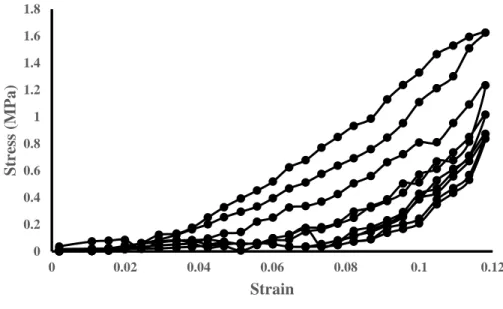
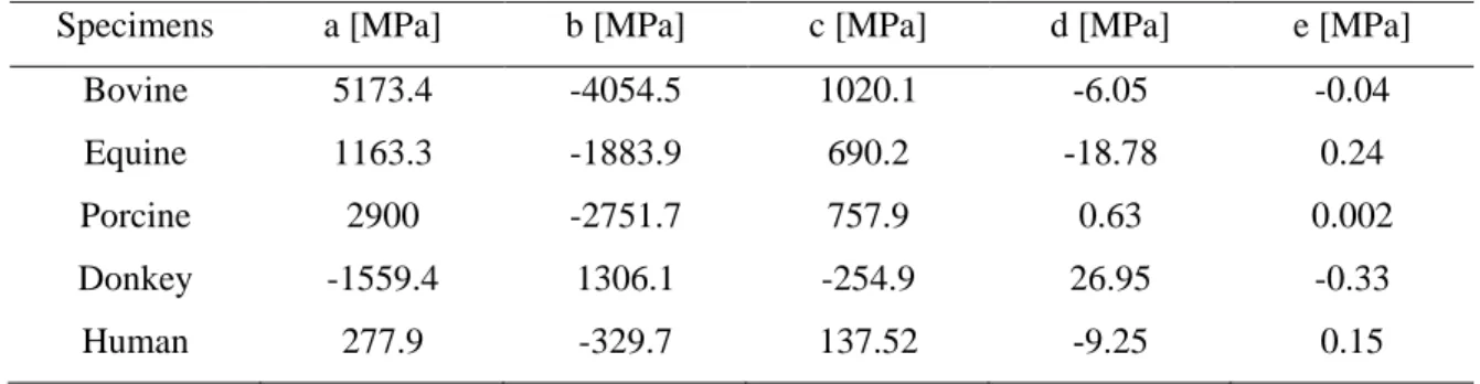
Figure 2-9. The average Cauchy stress–stretch data for bovine, equine, porcine and donkey pericardial tissues and human native aortic valve leaflets under tension in the fiber direction at crosshead speed 1 mm/s. Data are expressed as mean ±STD. ... 65
Figure 2-10. Bar graphs represent the ultimate tensile strength (UTS) (A), failure strain (B), and elastic modulus (C), for bovine (green), equine (black), porcine (red) , donkey (grey) pericardia and human aortic valve leaflets (blue) with speed 1 mm/s in fiber direction. ... 66
Figure 2-11. The average Cauchy stress–stretch data for bovine, equine, porcine and donkey pericardial tissues and human aortic valve leaflets in the axial (11) (A) and perpendicular (22) (B) directions. Data are expressed as mean ±STD. ... 67
Figure 3-1. Illustration of creep test [102]. ... 74
Figure 3-2. Illustration of stress relaxation test [102]. ... 74
Figure 3-3. Illustration of hysteresis test [102]. ... 75
Figure 3-4. Diagram of the uniaxial stress relaxation test system (1: micro stepper motors; 2: load cell). ... 76
Figure 3-5. Stress-strain curves obtained from the uniaxial mechanical test on all specimens in fiber direction at three extension rates. ... 85
Figure 3-6. Tensile moduli of bovine (A), equine (B) and porcine (C) pericardia evaluated at 0.02 (green), 0.20 (black) and 1.00 mm/s (red) extension rates in fiber direction. ... 85
Figure 3-7. Average stress relaxation curves for bovine pericardium (A), equine pericardium (B), and porcine pericardium (C) tissues at four different strain levels. ... 86
xi
Figure 3-8. Stress-strain curve to evaluate the linearity of viscoelastic properties of bovine (A),
equine (B), and porcine (C) pericardial tissues. ... 87
Figure 3-9. Stress relaxation curves at 30% strain rate of the bovine, equine, porcine and donkey pericardia and the human aortic valve leaflets. ... 91
Figure 3-10. Normalized stress curves to evaluate the relaxation amount of tissues ... 91
Figure 3-11. Instantaneous modulus (A), relaxation modulus (B) and relaxation percentage (C) for the bovine (green), equine (black), porcine (red) and donkey (gray) pericardia and the human aortic valve leaflets (blue) at 30% strain level in fiber direction. ... 95
Figure 4-1. The geometry of the valve without base. ... 99
Figure 4-2. Transvalvular pressure applied as loading in the simulation. ... 99
Figure 4-3. The geometry of the valve with base. ... 100
Figure 4-4. Constraint function for normal contact [133]. ... 104
Figure 4-5. Mesh independent for pericardium models without the valve base. ... 106
Figure 4-6. Mesh independent for pericardium models with the valve base. ... 107
Figure 4-7. Comparison of von Mises stress distribution in four types of pericardium tissues for the model without valve base in the fully-opened position. ... 108
Figure 4-8. Von Mises stress distribution in four types of pericardium tissues for the model without valve base in the fully-opened position. ... 109
Figure 4-9. Comparison of von Mises stress distribution in four types of pericardium tissues for the model without valve base in the fully-closed position. ... 110
Figure 4-10. Von Mises stress distribution in four types of pericardium tissues for the model without valve base in the fully-closed position. ... 111
Figure 4-11. Comparison of von Mises stress distribution in four types of pericardium tissues for the model with valve base in the fully-opened position. ... 112
Figure 4-12. Von Mises stress distribution in four types of pericardium tissues for the model with valve base in the fully-opened position. ... 113
Figure 4-13. Comparison of von Mises stress distribution in four types of pericardium tissues for the model with valve base in the fully-closed position. ... 114
Figure 4-14. Von Mises stress distribution in four types of pericardium tissues for the model with valve base in the fully-closed position. ... 115
Figure 5-1. Scanning electron microscopy observations of bovine, equine, porcine and donkey pericardia on serous and fibrous sides. ... 120
Figure 5-2. Light microscopy observations of bovine, equine, porcine and donkey pericardia with three stainings (HE, MT, and PSR under bright field and dark field). ... 122
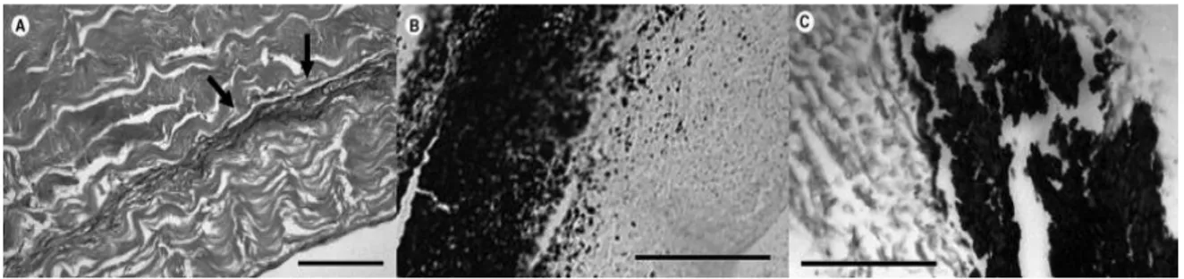
Figure 5-3. Structure of the collagen bundles from different pericardium tissues. A: bovine, B: equine, C: porcine, and D: donkey.The delaminations are marked by arrows. ... 123
Figure 5-4. Transmission electron microscopy observations of bovine, equine, porcine and ... 124
Figure 5-5. Deformation of pericardium tissue of the commercial Edwards SAPIEN 3 transcatheter heart valve after crimping (A), and illustration of the bending of the pericardium sheet (B). R: radius of curvature; θ: radian of curvature; L: length of neutral line; L1: length of the external layer; ∆L: change in length of the external layer; a: thickness of the pericardium sheet [146]. ... 126
Figure 6-1. SEM observations of the donkey pericardium. The serous side (outflow) of both non-decellularized and non-decellularized pericardial tissues features a smooth surface with undulation caused by the underneath wavy structure of collagen laminates at low magnification. The collagen bundles in the non-decellularized pericardium show a better defined structure compared to the decellularized one. They are scattered all over this smoothing surface of collagen fibers. The structure of the decellularized pericardium is more compact and scattered fibers are less frequent. ... 131 Figure 6-2. Cross-section of pericardia in histology where the fibrous portion (inflow) is on the left and the serous one (outflow) on the right. After decellularization, the H&E staining (upper panels) demonstrates that almost all the nuclei (dark) are eliminated and extracellular matrix components
xii
(pink) including collagen are preserved. Masson’s trichrome staining confirms these observations and show the presence of undulated collagen fibers (green) in both pericardial tissue types without a significant difference. Moreover, nuclei are not present in the decellularized pericardium, as well as capillary structures. Scale bars: 100 µm (small panels) and 50 µm (large panels). ... 132 Figure 6-3. Histology of the pericardium stained with picrosirius red under normal (above) and polarized (below) microscopy, confirming the waviness of collagen bundles. The decellularization results in minor contraction of the structure. Scale bars: 100 µm (small panels) and 50 µm (large panels). ... 133 Figure 6-4. TEM imaging of the non-decellularized (top) and decellularized (bottomn) donkey pericardial samples. A low magnification of the non-decellularized pericardium shows numerous cells, whereas in the decellularized one they look similar to ghost cells. ... 134 Figure 6-5. Representative Cauchy stress–stretch data for non-decellularized (top), and
decellularized donkey pericardia (bottom) under tension. Left-hand plots show the data in the axial (11) direction, while the right-hand ones in the perpendicular (22) direction. Fitted Fung models determined for these samples (solid red lines) are superimposed over the raw data ... 135
xiii
List of tables
Table 2-1. Comparison of genetic algorithm with other optimization methods [95] ... 61 Table 2-2. Average coefficients of fitting polynomial function (σ(λ)=aλ4+bλ3+cλ3+dλ+e) of order four for pericardium specimens and human aortic valve leaflet samples. ... 66 Table 2-3. Parameters in constitutive models for biaxial data. ... 67 Table 2-4. Average strain energy of the pericardia and human aortic valve leaflet ... 68 Table 3-1. Coefficients of the three-term Prony model for pericardium tissues at different strain levels ... 88 Table 3-2. Coefficients of the QLV model for pericardium tissues at different strain levels ... 89 Table 3-3. Coefficients of the three-term modified superposition model for pericardium tissues at different strain levels ... 90 Table 3-4. Parameters of the visco-hyperelastic model ... 92 Table 6-1. Parameters in the two constitutive models for biaxial data (P< 0.05) ... 136
xiv
List of abbreviations
Symbol Description
TAVI Transcatheter aortic valve implantation TAVs Transcutaneous aortic valves
MHVs Mechanical heart valves FEA Finite element analysis PHVs Prosthetic heart valves FEM Finite element modeling SEM Scanning electron microscopy TEM Transmission electron microscopy UTS Ultimate tensile strength
GOA geometric orifice aperture
MM Medtronic Mosaic
EPM Edwards Perimount Magna PTFE Polytetrafluoroethylene
PU Polyurethane
PEU Poly(ether urethane) PCU Poly(carbonate urethane)
POSS-PCU Polyhedral oligomeric silsesquioxane poly(carbonate-urea) urethane SSAV Semi-stented surgical aortic valve
SIBS Poly (styrene-b-isobutylene-b-styrene) PAS Platelet activity state
EOA Effective orifice area
TEHV Tissue engineered heart valve PGA Polyglycolic acid
UCC Umbilical cord cells P4HB Poly-4-Hydroxybutyrate STL Stereolithographic ECM Extracellular matrix
xv bFGF Basic fibroblast growth factor MSCs Mesenchymal stem cells GA Genetic algorithm GOH Gasser-Ogden-Holzapfel
xvi
Declaration
I declare that this thesis represents my own work and contains no material which has been accepted for the award of any other degree, diploma or qualification in any universities except where due reference has been made in the text of the dissertation. To the best of my knowledge and belief, this thesis contains no material published or written by another person except where due acknowledgement has been made.
xvii
Acknowledgements
Firstly and foremost, I would like to express my sincere gratitude to my supervisors Prof. Nasser Fatouraee, Prof. Robert Guidoin, and Prof. Ze Zhang for their continuous support of my Ph.D. project, their patience, motivation, and immense knowledge. Their guidance helped me in all aspects of my research and writing of this thesis. Prof. Guidoin also played a key role in defining and carrying out of my Ph.D. project.
I thank the BioSud, Buenos-Aires, Argentina and the Changhai Hospital of Naval Military Medical University Shanghai China for supplying the pericardia free of charge.
I would like to thank all my colleagues in the biofluid group of Amirkabir University and the biomedical group of Laval University for their assistance during my Ph.D. candidature. To all my friends, thank you for your understanding and encouragement. It is impossible to list all your names here, but you are always on my mind.
I wish to thank my beloved parents for their faith in me, their everlasting support, and their motivation throughout my life. Finally, and most importantly, I would like to thank my husband for his support, quiet patience, and sacrifice.
1
2
Background
The treatment of heart valve diseases varies according to the type and severity of the diseases. In general, there is no medication to cure such a disease. Hence, replacing the dysfunctional valve by a prosthetic heart valve is often preferred. There are two types of artificial heart valves currently used, i.e., biological valves and mechanical heart valves (MHVs). Determining which type of the valve is appropriate for a patient depends on the nature of the valve diseases as well as the patient’s age and medical history. The MHVs are often implanted in patients younger than 65 years old, while the bioprosthetic valves are used mainly in elderly. Now more than half of the implanted valves are bioprosthetic, especially after the introduction of transcatheter aortic valve implantation (TAVI) in 2007 [1].
Each type of the prosthetic valves has its own limitations. MHVs have an excellent durability (25-30 years) but need lifetime anticoagulation, raising concerns about thromboembolism and hemorrhage [1]. The recent generation of MHVs still has turbulence and areas of high shear stress, which induce platelet activation, aggregation, and deposition [2]. Biological valves don’t need anticoagulation, but they are susceptible to calcification. Durability is the main problem of them, which lasts 10 to 15 years [1].
Motivation
Biological valves are preferred because of their reasonable durability, no need for anticoagulant and importantly the capability to be delivered through catheters. Knowing that the mechanical property and collagen structure of the pericardial tissues greatly affect the strength and durability of the prosthetic valves [3], a careful investigation of the anisotropic collagen structure and the correlation with the biaxial mechanical properties becomes extremely important. Furthermore, because pericardium is a fragile material, any mishandling, and even the normal crimping/ballooning, can lead to a dramatic damage to it particular at the surface layers of the leaflets [4]. Such damages were found substantial in the deeper layers of small diameter devices [5], [6]. These damages can impair the biofunctionality and biodurability of the device, and aggravate the thrombogenicity of the flow surface [7]. So it is necessary to select an appropriate tissue that is more resilient to the handing, crimping and deployment procedures.
3
Objective
The goal of this thesis therefore is to identify the most appropriate tissue with long durability to manufacture bioprosthetic heart valves by analyzing the mechanical and histological properties of equine, porcine, and donkey pericardia with respect to those of bovine pericardium and human aortic valve leaflets.
Therefore, this study aims to:
Extract the comprehensive mechanical properties of pericardium tissue and native aortic valve leaflets;
Develop finite element analysis (FEA) to evaluate the valve durability;
Extract the histological properties of the pericardium tissues to evaluate the structure and arrangement of the fibers of the tissues;
Thesis outline
This thesis consists of six chapters. They are summarized as follows:
Chapter 1
A thorough review of the scientific literature concerning approaches to developing prosthetic aortic heart valves is provided. The literature review includes the limitations of commercially available prosthetic heart valves (PHVs) and the problems of the underdevelopment valves. Finally, based on these findings, a realistic solution to developing an alternative aortic valve with high biofunctionality and biodurability is proposed.
Chapter 2
This chapter provides a brief review of the types of mechanical tests to extract the elastic mechanical properties of the tissues. The optimization methods to obtain the parameters of the constitutive models which represent the elastic properties of the samples. Finally, the results of the elasticity measurements of the tissues are provided.
4
Chapter 3
This chapter provides a brief review of the types of mechanical tests to extract the viscoelastic mechanical properties of the tissues. The optimization methods to obtain the coefficients of the constitutive models which describe the viscoelastic properties of the samples. Finally, the results of the viscoelastic measurements of the tissues are provided.
Chapter 4
In this study, numerical analysis was performed on heart valve prosthetics with different leaflets, and the type of solution is based on the contact theory. The purpose is to investigate the stress on the valve leaflets during the opening and closing the valve. So at the beginning of this chapter, the theory of this analysis is introduced. In this study, all dimensions used for the model are based on the dimensions of the aortic valve. We then describe the modeling steps in Adina software. A detailed description of the applied load conditions, boundary conditions, and solid properties are discussed separately in this chapter.
Chapter 5
In this chapter, the structures of the different pericardia are compared. The structure of the collagen bundles in the leaflets acts as a key factor in determining the in vivo fate of the valves. The preservation of the wavy structure and individualized collagen filaments is known to play an important part in determining the mechanical properties of the pericardium. One of the objectives of this study was to characterize the thickness and structure of porcine, equine, and donkey pericardium in order to assess their suitability as an alternative material for the manufacture of transcatheter heart valves. In this chapter, the pericardium specimens were sampled from equine, porcine, and donkey pericardium tissue. The results were compared with the bovine pericardia through light microscopy, scanning electron microscopy (SEM), and transmission electron microscopy (TEM).
5
Chapter 6
In this chapter the potential benefits of decellularization are evaluated. The presence of cells in the traditional type of fixation is questionable, but no answer has yet been found. Nowadays, some researchers have concluded that the decellularization method can achieve better results than traditional fixation. So in this chapter, we compare non-decellularized and decellularized donkey pericardium tissues mechanically and histologically.
6
1
Chapter 1
7
1.1 Introduction
The literature review presented in the following sections comprises a complete review of the scientific literature concerning the approaches in developing prosthetic aortic heart valves. Limitations of the commercially available PHVs and the problems of those under development are discussed. Finally, based on these findings, a realistic solution to develop aortic valves with high biofunctionality and biodurability is proposed.
1.2 Heart structure
The heart is an irregular cone consisting of four chambers (left atrium, left ventricle, right atrium, and right ventricle) and four valves (mitral, tricuspid, pulmonary, and aortic) as illustrated in Figure 1-1. The heart lies between the right and left pleural sacs in the middle mediastinum. One-third of the heart is to the right of the median (sagittal) plane of the body and two thirds to the left of this plane [8].
The two upper chambers (atria) are separated by a structure called the interatrial septum. Similarly, the two lower chambers (ventricles) are separated by a structure called the interventricular septum. The valves allow the blood to flow in one direction and prevent the return of blood [9].
The mitral valve is located between the left atrium and the left ventricle, while the tricuspid valve is between the right atrium and the right ventricle. The pulmonary valve connects the right ventricle with the pulmonary artery; and the aortic valve connects the left ventricle with the ascending aorta. The mitral and tricuspid valves are called atrioventricular valves, and the pulmonary and aortic valves are called semilunar valves. The atrioventricular valves are attached to the myocardium by the papillary muscles and fibrous cords and are responding to myocardial contractions. The semilunar valves do not have a direct attachment to the myocardium [9].
8
Figure 1-1 Anatomy of the heart [10].
1.3 Aortic valve
The aortic valve is located at the left ventricular outlet, allowing blood to enter the aortic artery and preventing backflow. The valve consists of three half-moon shaped leaflets in the vicinity of the Valsalva sinus (Fig. 1-2). The aortic valve opens and closes approximately 103,000 times daily and 3.7 billion times in its lifetime. Since the aortic valve is located on the high blood pressure area, this valve experiences the highest pressure, fatigue, and strains [8].
1.4 Aortic valve diseases
Aortic valve diseases are common clinical problems that are likely to increase with the aging population. Aortic valve abnormalities can generally be classified into two groups: valve incompetence, such as aortic valve leakage, and valve obstruction and insufficiencies, such as stenosis or sclerosis [11].
9
Figure 1-2 Aortic valve [12].
1.4.1 Aortic stenosis
Aortic stenosis can be due to subvalvular, valvular, or supravalvular obstruction to the left ventricular outflow. Subvalvular aortic stenosis usually occurs as a fibromuscular membrane or narrowing of the left ventricular outflow tract. Supravalvular aortic stenosis usually occurs due to a congenital narrowing of the ascending aorta and usually begins just above the sinuses of Valsalva. Valvular stenosis is the most common type of aortic valve stenosis and is caused by an abnormality of the aortic valve leaflets. The causes of valvular aortic stenosis can be divided into congenital, rheumatic, and degenerative stenosis. Congenital aortic stenosis accounts for the most cause of valvular stenosis in young adults and may be unicuspid, bicuspid, or tricuspid. A bicuspid valve is most common in males and accounts for 1-2% of the population. The two leaflets are usually of unequal size with the larger leaflet generally having a raphe, which may give the appearance of a tricuspid valve.
10
Unicuspid valves produce severe obstruction in infancy and thus are rarely encountered in adults [4,6].
Degenerative aortic stenosis is most common in the elderly and accounts for the majority of cases in adults. It usually develops after years of mechanical stress on a normal aortic valve. It also occurs due to progressive calcium deposition at the leaflet bases, which limits the movement of the leaflet (Fig. 1-3). It is the most common form of aortic stenosis in patients for aortic valve replacement [11].
1.4.2 Aortic regurgitation
Aortic regurgitation or leakage occurs when the valve doesn’t close properly, causing blood backflow into the left ventricle. The ventricle normally adapts to this abnormality by enlarging itself to accommodate the greater workload. In fact, in pure or predominant regurgitation, the left ventricle is able to comply for a long time with the volume and pressure
overload due to the compensatory mechanisms. Aortic stenosis is also one of the major causes
of aortic leakage, resulting in eccentric left ventricular dilation and hypertrophy [11].
11
1.5 Currently available Prosthetic Heart Valves
Currently, there are no medications to cure heart valve diseases, leaving surgical treatment the only option. Depending on the severity and type of the disease, the treatment can be either repairing the valve or replacing it with a PHV. In case of replacing the valve, determining which type of prosthetic valve is most appropriate for a particular patient depends on the nature of the heart valve diseases as well as the patient’s age and medical history. Currently, there are two types of PHVs used, i.e., mechanical valves and biological valves.
1.5.1 Mechanical valves
The first mechanical heart valve (MHV) was introduced in 1952. Over the years, more than 30 different designs have been manufactured all over the world. The development of these valves began with the simplest caged-ball valves, then evolved into the tilting disc (monodisc) and bileaflet valves.
1.5.1.1 Caged-ball valves
As the first generation of mechanical valves, the ball and cage design consists of a ball held in a cage (Fig. 1-4-A). It was first implanted in 10 patients by Dr. Charles A. Hufnagel, of which six survived the surgery. That was the first success of the artificial heart valves. The valve was made of an acrylic ball that was placed in a plexiglass cage [15].
The Starr–Edwards valve is the most famous ball and cage valve. The original ball of this valve is made of the Silastic, held by a stellite alloy cage. During diastolic, the ball blocks the metal rings or the backflow [16]. Another popular valve is the Smeloff–Cutter, which was introduced into clinical use in 1964. In this model, the Silastic ball does not sit at the titanium alloy ring but is stopped by another smaller cage. This design allows a small amount of backflow and prevents blood clots formation. The most important problems of the Smeloff–Cutter valve are high pressure drop and poor flow pattern [17].
Later, to reduce thromboembolism, the ring was covered with a polypropylene fabric with the intention to grow a layer of endothelium. By decreasing blood contact with the outer
12
surface of the cage, the clotting rate decreased. However, the probability of fabric rupture was very high after several years of implantation.
The ball and cage design completely blocks central flow. So blood needs more energy to bypass the ball. In addition, such valves became highly unpopular due to the damage to blood cells caused by their collision with the valve body, causing the formation of small clots. Therefore, the patients must take anticoagulant for the rest of their life [17].
1.5.1.2 Tilting disc valves
In the 1960s, a new type of prosthetic valves was developed, which used a diagonal disc instead of the ball to better mimic natural blood flow. The disk held to the textile-covered metal ring by two fasteners opens and closes during blood flow. While this valve, called a tilted disk, could well prevent blood pressure drop, it was quickly eroded. For this reason, in 1969, a new type of tilted disk was made with a floating disc of Delrin, which, at the opening of the valve, was like an airfoil in the bloodstream with an angle depending on the disk holders. The floating design of the disc eliminates the joints and hence no tear. The lifetime of this type of valves was longer than the previous model. In 1971, the Delrin disk was replaced by a pyrolytic carbon disk because it does not react with blood and does not swell and stagnate in the valve. This minimizes the risk of destroying the valve due to excessive opening and closing and breakage of the fasteners [18].
Currently, the most common model of the tilting disc is the Medtronic - Hall model, which has been in clinical use without modification since 1977 (Fig. 1-4-B). It was designed to have the largest orifice area [19], [20].
The tilting disc valves are far better than the cage-ball valves. Many tilting disk valve models have been known for decades for their ability to prevent artificial valve leakage, endocarditis, and clotting.
1.5.1.3 Bileaflet valves
In 1979, the first two-leaflets valves called "St. Jude Cardiac valve prosthesis" were introduced, which included two discs instead of one (Fig. 1-4-C). The two semicircular discs
13
rotate around a hinge. These valves are more capable of controlling blood flow and clot formation and reducing bacterial infection than previous types [15].
Carbon leaflets are very strong and have high blood compatibility. The leaflets open completely by rotating around the hinge and move in the direction of blood flow. Because the leaflets can’t close completely and unavoidably generating some backflow, the bileaflet valves are still not ideal [17].
The bileaflet valve distinguishes itself from other mechanical valves by its central flow as in a healthy heart, and a larger effective orifice area (EOA). The least disturbance to the central flow causes less damage to blood cells and so requires less anticoagulant [17]. The bileaflet valves are the safest mechanical valves known.
An important issue with the mechanical valves is the hemorrhagic complications. This risk is permanent across all types of mechanical valves. However, the strength of anticoagulant treatment differs with respect to the type of mechanical valves [21]. While the performance of the mechanical valves has been improved due to better material blood compatibility and hemodynamics, leading to a lower thromboembolic risk [21], patients implanted with mechanical valves still need lifelong anticoagulation, meaning the risk of thrombogenic complications. Even the recent generation of MHVs still has turbulence and the areas of high shear stress, which induce platelet deposition, aggregation, and activation [2], [22]. The accumulative effect of repeatedly passing through the valve also results in the platelets beyond their activation threshold [23]. In addition, the blood disruption and flow abnormalities also damage other types of blood cells. However, despite these disadvantages, MHVs have a high durability.
14
Figure 1-4. (A) Caged-ball valves; (B) Disc valve, Medtronic–Hall; (C) Bilealet valve, St. Jude Medical [16].
1.5.2 Biological valves
The rationale for the development of biological valves was to reduce the risk of complications related to the MHVs, i.e., thrombosis and bleeding due to anticoagulation [16]. Biological valves include homografts, pulmonary autografts, porcine aortic valves, and bovine pericardial valves. Bioprosthetic valves can be divided into stented and stentless valves. The stented valves consist of the valve leaflets mounted on a polymeric or alloy stent frame, and a circular or scallop-shaped external sewing ring placed outside of the stent frame. The stentless valves on the other hand have neither the stent frame nor the base ring. The stentless valves are designed to achieve a large orifice area to obtain a superior flow pattern and better hemodynamic features [24]. Recently, transcatheter valves represent a significant proportion of the aortic bioprostheses. The most popular transcatheter aortic valves implanted to date have been the balloon-expandable Edwards Sapien valves (Fig. 1-5) and the self-expandable CoreValve system. Prior to deployment, the valves must be crimped to fit in a delivery sheath. The crimping procedure looks similar to crushing the tissue. Such a crude procedure damages the leaflets to different degrees [4].
A biological valve is either a porcine aortic valve or a valve assembled from bovine pericardium that is fixed with glutaraldehyde that crosslinks and stabilizes the tissue. The crosslinks reduce the biodegradability and antigenicity of the tissue, modify its mechanical properties, and reduce its thrombogenicity [25], [26]. Bioprosthetic valves do not require
15
anticoagulation but are susceptible to calcification. They currently last about 15 years, after which another surgical intervention may be required. Studies have aimed at creating a bioprosthesis with the tissue leaflets that would show a long-term structural stability [11].
1.5.2.1 Porcine Valves
There are different models of porcine aortic valves that are commercially available, such as the popular St. Jude Medical–Epic (Fig. 1-6). Pigs are selected because of the anatomic similarities between them and human beings. The valves are harvested and treated chemically to prevent foreign body rejection. Leaflet tears and dehiscence are the main failure mode of porcine valves can be due to many factors, including mechanical stresses, calcification, and material deterioration [27]. Researchers have compared porcine valves with pericardium valves. In a clinical study of 108 patients, 54 patients received the Medtronic Mosaic (MM) porcine valves, and 54 others received the Edwards Perimount Magna (EPM) bovine pericardial valves [28]. At 5 years, the EPM valves were found significantly superior to the MM prostheses based on the hemodynamic analyses and the clinic incidence, i.e., prosthesis mismatch and regression of left ventricular mass index. The hemodynamic superiority of the EPM prostheses in comparison to the MM prostheses appeared in the first year and became more significant over time. In general, researchers have concluded that bovine valves are superior because of the low percentage of adverse events and better hemodynamic
16
Figure 1-5 Bioprosthesis Edwards–Sapien designed for transapical aortic valve implantation [16].
17 1.5.2.2 Pericardium valves
The pericardium tissue used in manufacturing the bioprosthetic heart valves encloses the heart and consists of two layers, namely, fibrous and serous layers (parietal and visceral) (Fig. 1-7). The collagen fibres in the two layers align in different directions. Such an arrangement of the fibres gives the pericardium its viscoelastic properties and the ability to deform in all directions [8], [30], [31]. In order to choose an appropriate pericardial tissue to construct better heart valves, researchers have performed different experiments and tested the pericardia from different animal species.
Figure 1-7. Structure of heart wall [32].
Inflation tests on ostrich pericardium
In this research [33], ostrich pericardium was proposed as an alternative to bovine pericardium. The ostrich pericardia were cut circularly to a diameter of 2 cm and fixed in a 0.625% glutaraldehyde solution for 24 hours. The pericardium was sutured, and the tests were repeated with the sutures. Hydrostatic pressure was applied to the ostrich membrane using a hydraulic simulator. The tensile strength of the tissue was recorded up to the point of rupture. Since the load was applied to the leaflets through the sutures, high shear stress was created in the tissue adjacent the sutures and damaged the prosthesis. In this study, the tensile
18
strength was calculated using Laplace's formula for thin-walled membranes as following [33]:
(1-1) where Ts is the tensile strength, p is the pressure, r is the radius of the membrane, and e is the thickness of the membrane. The elongation was measured by the changes in length of the longest arc of the dome. The tensile strength /elongation ratio was calculated using the least-squares method. The best fit for the data was:
(1-2) The tensile strength of the ostrich pericardium was maximally 55 MPa and minimally 30 MPa, whereas the strengths of the canine and calf pericardia were approximately 13 and 9 MPa respectively [33]. The tissue stiffness was also calculated when different types of sutures were used, among which the tissue sutured with the silk suture showed the highest tensile strength compared to the tissues sutured with the nylon suture.
Investigating the mechanical properties of pericardium using finite element analysis In this study [25], the effect of the mechanical properties of the pericardium on the mechanical behaviors of the valve has been investigated using the finite element model (FEM). The geometry used in this study was extracted from the Pericarbon Sorin S.p.A. biological aortic valve (Fig. 1-8).
The pressure difference between the ventricle and the aorta was applied to the model as the loading. At first, the mechanical properties of the glutaraldehyde fixed pericardial tissue were extracted using the uniaxial tensile tests in three directions, as showed in Figure 1-9. As shown in the figure, the tissue was anisotropic, with the 0˚ strips having a higher elastic modulus. According to the experimental data, in the modeling, the tissue texture was considered orthotropic. In FEM, two models with two different Young’s moduli in two directions were considered. According to the orthotropic material, two orthogonal axes were considered with reference to radial (r) and circumferential (c) valve directions. The models A and B, with the Er=3.4 MPa and Ec=4.3 MPa for model A and the Er=4.3 MPa and Ec=3.4 MPa for model B, were considered. Finally, it was concluded that the model A had a better behavior in regard to the load curve, without any delay during either the opening or the closing phase. This behavior was also very similar to what we saw in real human valve
2 3 1 2 3 y b x b x b x / 2 s T pr e
19
leaflets. The stress distribution was also investigated, in which the model B showed the higher Von Mises stress values compared to the model A [25].
Figure 1-8. The Pericarbon Sorin S.p.A. aortic valve and the geometric model in closed configuration [25].
Figure 1-9. a. Cutting directions for one sample b. Stress-strain mean curves for specimens [25].
Chemical and mechanical tests of ostrich pericardium
In this study [34], the biochemical characteristics (histology, water content, amino acid composition, and collagen and elastin contents), mechanical properties, and calcification in a subcutaneous rat model were measured. For mechanical test, 12 specimens of the ostrich pericardium were prepared for uniaxial test in comparison with the same number of the
bovine pericardial specimens. The stress-strain data were fitted to the equation y= a1x + a2x2
20
of elongation. The ostrich pericardium showed a stiffer behavior than the bovine pericardium (Fig. 1-10).
Figure 1-10. Stress–strain curves for ostrich and calf GA-stabilized pericardium [34].
For histology, the native and glutaraldehyde treated tissue samples were fixed in 4% formaldehyde in PBS, processed and stained with hematoxylin–eosin to assess general morphology and with the orcein van Gieson technique to visualize elastin. The glutaraldehyde treated ostrich pericardial tissue revealed a normal morphology, presenting a well-structured pattern of collagen fibers.
The water content of the glutaraldehyde-stabilized ostrich pericardium was higher than that of the bovine origin. The ostrich pericardium was also thicker than the bovine pericardium. In addition, the amino acid content of the tissues was investigated. It was concluded that the amount of amino acids in the glutaraldehyde treated tissues was not significantly different from that in the native tissues. The authors also examined the elastin and collagen content of the native ostrich and native bovine tissues. According to the study, elastin was 1.6 times lower in the ostrich tissue than in the bovine tissue, whereas no significant difference in the collagen content of the two tissues.
In this study, six pericardial specimens of 1 cm in diameter were implanted in the abdominal muscle of mice for 30 and 60 days. At the end of this period, the implanted tissues were extracted for histological analysis and to test the calcium phosphate levels. There was no significant difference between the two tissues within the first 30 days regarding tissue
21
degradation. However, after 60 days, the amount of calcium phosphate in the bovine tissue was much higher than that in the ostrich tissue, and the rate of tissue destruction in bovine was greater (Fig. 1-11). Finally, based on these tests, the authors concluded that the ostrich pericardial tissue was mechanically and chemically similar to the bovine pericardium and even better [34].
Figure 1-11. Light microscopic appearance of pericardium after implantation. After 30 days (A: ostrich pericardium) and 60 days (B: ostrich pericardium; C: calf pericardium) implantation in a
subcutaneous rat model [34].
Investigation of the micromechanical behaviors of bovine pericardium using uniaxial tensile tests
In this study [35], the micromechanical behaviors of the glutaraldehyde fixed bovine pericardium were investigated using the uniaxial tensile tests and digital imaging. The uniaxial tests were performed at a rate of 0.02 mm/s. A high-resolution optical camera was used to obtain the digital images of the specimens during the test.
The curve of the uniaxial tensile tests is composed of three regions. The first region corresponds to a small elongation from point O to A in Figure 1-12a, which represents the alignment of the collagen fibers along the direction of the tensile force. The second region corresponds to a linear behavior located between points A to B, where the fibers are mainly aligned in the direction of the applied load. Finally, the third region corresponds to the critical limit B, beyond which the curve shows a nonlinear behavior and finally the rupture of the fibers at point C.
At the beginning of the stress–stretch curve, a non-smooth displacement vector field was observed due to the initial collagen fiber alignment with respect to the direction of the force as shown in Figure 1-12b. When the fibers were completely aligned, the displacement vector field took the shape of a hyperbolic displacement field, shown in Figure 1-12c. This behavior
22
was observed in the linear region between A and B. Finally, when the critical limit was reached, the mechanical response became nonlinear again; and from the displacement vector field, it could be inferred that the fibers had begun to split, indicating the failure of the material (Fig. 1-12d) [35].
Figure 1-12. a. Critical points in the stress versus λ–λ−2 ratio curve b. fiber alignment; OA segment. c. start of the linear behavior; AB segment d. second nonlinear behavior; BC segment [35].
The fatigue behaviors of the glutaraldehyde fixed calf pericardium
In this study [36], the fatigue behaviors of the calf pericardium treated with glutaraldehyde were investigated based on two indications of injury, i.e., tissue deformation and energy loss. To perform the tests, circular specimens were attached to a tube filled with saline. The fluid pressure inside the tube was then slowly increased till reaching a fixed value (mean pressure Pm). The pressure was then modulated into a sinusoidal oscillation symmetrical to the Pm at a predesigned amplitude and 1 Hz. Five thousands cycles at one particular combination of pressure amplitude and mean pressure were performed. Deformation in the middle of the sample was measured and the energy required for this deformation was calculated assuming a spherical deformation. The energy levels were also measured after 10 and 5000 cycles. The overall energy and the energy after 10 cycles were investigated at different mean pressures and different deformations. The energy curve respect
23
to different mean pressures was exponentially, and it was linear respect to different pressure ranges (Fig. 1-13). The energy diagrams and diameter changes were also linear. It was concluded that both the mean and the oscillatory pressures increased the damage, and the tissue used for prosthesis should be more rigid to withstand the pressures[36].
Figure 1-13. (a) E10 − Pm and (b) E10 − ΔP tendency curves [36].
Evaluation of the kangaroo pericardium using biaxial tensile test
In this study [37], the mechanical properties and stress distribution across the leaflet either made of kangaroo or bovine pericardium were evaluated using FEM. Two valve geometries were investigated and compared to each other. One valve had a geometry similar to that of the native aortic valve, therefore the parameters proposed by Thubrikar could be used. The other valve design had attachments at the commissures that go straight down, which causes this valve not to have a distinct hyperbolic shape at the base (Fig. 1-14).
24
Figure 1-14. Two valve geometries used for Finite element models [37].
The stents were designed with an outer diameter of 20 mm and a wall thickness of 0.5 mm for in vivo trials in sheep. In this study, before FEM modeling, the mechanical behaviors of the kangaroo and bovine pericardia were extracted using the biaxial tests (Fig. 1-15). Fung’ constitutive equation improved by Sun and Sacks was used as bellow:
2 2 2 1 11 2 22 3 11 22 4 12 5 12 11 6 12 22 [ 1] 2 2 2 2 Q C W e Q A E A E A E E A E A E E A E E
(1-3)
where W is the strain energy per unit mass of the tissue, Eij is the Green strain tensor, and C and Ai are material constants. FEM was performed to compare the pericardium samples with human aortic leaflets. The strain energy in the center of each model was determined. It was concluded that thicker bovine and kangaroo pericardia exhibited lower strain energy and requires less work against the internal forces than in the case of the native human valve tissue. This suggests that the bovine and kangaroo tissues would be mechanically fit for manufacturing heart valve prostheses.
FEA was also used to evaluate the concepts A and B (Fig. 1-16), in order to choose the most feasible design for in vivo studies. Both normal and hypertensive pressure differences across the valve were examined. The leaflet attachment forces were determined to investigate the probability of tissue tearing. The stress distribution across the leaflet was evaluated during both systole and diastole. Both concepts were simulated in the modified Fung constitutive
25
model using the properties extracted from the bovine and kangaroo pericardial materials. The concept B showed more locations of higher stress concentration in all cases, especially at the base, and the significant folding at the corners. So the concept A is probably more preferable [37].
Figure 1-15. Nonlinear regression fitting results for the normal stresses for kangaroo pericardium [37].
26
Morphological and mechanical comparison of the bovine and porcine pericardia In this study [38], the bovine and porcine pericardial tissues were compared to both morphologically and mechanically. The pericardial tissues were first harvested in the slaughterhouse and transferred to the laboratory in cold saline. They were cleaned of fatty tissue and finally fixed in a glutaraldehyde solution.
The histological observations were performed using the images from SEM, light microscopy and TEM. The uniaxial tensile tests were performed on the specimens to investigate the mechanical properties. It should be noted that in this study, the grip-to-grip distance represented the gauge length of the samples. The thickness of the porcine and bovine pericardia were 280±30 and 260±30 μm, respectively. The samples were preconditioned with three cyclic loading sequences estimated to 10% of failure strain prior to testing. The specimens were loaded to failure at a displacement rate of 12 mm/min. Ultimate tensile strength (UTS) and failure strain were defined by the peak stress and the maximum deformation withstood by the samples prior to failure. Tensile modulus was defined as the slope of the linear portion of the stress–strain curve that normally comprised between 25% and 80% of the UTS.
It was concluded that the porcine pericardium was more prone to wrinkle when compared to its bovine counterpart, which was found stiffer. Also, the bovine pericardium showed more loose collagen bundles than the porcine pericardium did (Figs. 1-17 and 1-18). The Young’s modulus of the bovine pericardium was higher than that of the porcine pericardium (Fig. 1-19). Also, in this study, the tensile tests were performed in both axial (fiber direction) and perpendicular directions. The results showed that the final stress and elastic moduli calculated in the direction perpendicular to the fibers were significantly lower than that calculated at the axial direction of the fibers. Finally, this work concluded that the porcine pericardium is better than the bovine pericardium because of the structure and the relationship between collagen bands [38].
27
Figure 1-17. Scanning electron microscopy of both sides of the bovine pericardium i.e. serous side, inflow (A1 and A2), and fibrous side, outflow (B1 and B2). The serous side is smooth and glistening and has damaged mesothelial cells on its surface. On the other hand, the fibrous side fails
28
Figure 1-18. Scanning electron microscopy of both sides of the porcine pericardium i.e. (serous side A1 and A2) and fibrous side (B1 and B2). The serous surface is smooth and glistening with a wavy
morphology, caused by the crimping of the underlying bundles of collagen. The fibrous surface shows collagen bundles that are not incorporated in the structure [38].
29
Figure 1-19. Ultimate tensile strength (UTS) for bovine (black) and porcine (grey) pericardia [38].
Investigation of the size of the stent using a finite element model
The objective of this study [39] was to determine the impact of the incomplete TAV
stent expansion on TAV leaflet stress and strain distributions. Such increased mechanical
stress and flexural deformation may lead to an accelerated tissue degeneration and reduced durability. In this study, the computational simulation results of incompletely expanded TAVs were compared to that of the fully-expanded circular TAVs.
A planar biaxial stretching system was used to determine the mechanical properties of the bovine pericardium patch (Fig. 1-20). The Fung stress-strain function was fitted to the data: 2 2 [ 1] 2 2 Q xx xx xy xx yy yy yy c W e Q c E c E E c E (1-4)
where Ex and Ey are the Green strains in x and y directions, respectively. cxx, cyy, cxy, and c are the material constants.
The FEM was performed using the ABAQUS/Explicit package. In the simulations, only the leaflets were modeled, and the stent was considered rigid. A transvalvular pressure waveform determined from repeated in vitro tests was applied to the leaflets as loading.
![Figure 1-5 Bioprosthesis Edwards–Sapien designed for transapical aortic valve implantation [16]](https://thumb-eu.123doks.com/thumbv2/123doknet/2908980.75495/34.918.298.621.103.422/figure-bioprosthesis-edwards-sapien-designed-transapical-aortic-implantation.webp)
![Figure 1-9. a. Cutting directions for one sample b. Stress-strain mean curves for specimens [25]](https://thumb-eu.123doks.com/thumbv2/123doknet/2908980.75495/37.918.138.782.486.709/figure-cutting-directions-sample-stress-strain-curves-specimens.webp)
![Figure 1-10. Stress–strain curves for ostrich and calf GA-stabilized pericardium [34]](https://thumb-eu.123doks.com/thumbv2/123doknet/2908980.75495/38.918.251.659.191.469/figure-stress-strain-curves-ostrich-calf-stabilized-pericardium.webp)
![Figure 1-15. Nonlinear regression fitting results for the normal stresses for kangaroo pericardium [37]](https://thumb-eu.123doks.com/thumbv2/123doknet/2908980.75495/43.918.249.661.243.567/figure-nonlinear-regression-fitting-results-stresses-kangaroo-pericardium.webp)

![Figure 1-28. The measurement of PAS for the bileaflet mechanical valve and SIBS valve [61]](https://thumb-eu.123doks.com/thumbv2/123doknet/2908980.75495/55.918.236.668.606.902/figure-measurement-pas-bileaflet-mechanical-valve-sibs-valve.webp)