i
Reliable Message Dissemination in Mobile Vehicular
Networks
par Benrhaiem Wiem
Département d’informatique et de recherche opérationnelle Faculté des arts et des sciences
Thèse présentée Thèse présentée à la Faculté des études supérieures en vue de l’obtention du grade de Philosophiæ Doctor (Ph.D.)
en computer science
Avril, 2017
© Benrhaiem Wiem, 2017
ii
Les réseaux véhiculaires accueillent une multitude d’applications d’info-divertissement et de sécurité. Les applications de sécurité visent à améliorer la sécurité sur les routes (éviter les accidents), tandis que les applications d’info-divertissement visent à améliorer l'expérience des passagers. Les applications de sécurité ont des exigences rigides en termes de délais et de fiabilité ; en effet, la diffusion des messages d’urgence (envoyés par un véhicule/émetteur) devrait être fiable et rapide. Notons que, pour diffuser des informations sur une zone de taille plus grande que celle couverte par la portée de transmission d’un émetteur, il est nécessaire d’utiliser un mécanisme de transmission multi-sauts. De nombreuses approches ont été proposées pour assurer la fiabilité et le délai des dites applications. Toutefois, ces méthodes présentent plusieurs lacunes.
Cette thèse, nous proposons trois contributions. La première contribution aborde la question de la diffusion fiable des messages d’urgence. A cet égard, un nouveau schéma, appelé REMD, a été proposé. Ce schéma utilise la répétition de message pour offrir une fiabilité garantie, à chaque saut, tout en assurant un court délai. REMD calcule un nombre optimal de répétitions en se basant sur l’estimation de la qualité de réception de lien dans plusieurs locations (appelées cellules) à l’intérieur de la zone couverte par la portée de transmission de l’émetteur. REMD suppose que les qualités de réception de lien des cellules adjacentes sont indépendantes. Il sélectionne, également, un nombre de véhicules, appelés relais, qui coopèrent dans le contexte de la répétition du message d’urgence pour assurer la fiabilité en multi-sauts. La deuxième contribution, appelée BCRB, vise à améliorer REMD ; elle suppose que les qualités de réception de lien des cellules adjacentes sont dépendantes ce qui est, généralement, plus réaliste. BCRB utilise les réseaux Bayésiens pour modéliser les dépendances en vue d’estimer la qualité du lien de réception avec une meilleure précision. La troisième contribution, appelée RICS, offre un accès fiable à Internet. RICS propose un modèle d’optimisation, avec une résolution exacte optimale à l'aide d’une technique de réduction de la dimension spatiale, pour le déploiement des passerelles. Chaque passerelle utilise BCRB pour établir une communication fiable avec les véhicules.
iii
Vehicular networks aim to enable a plethora of safety and infotainment applications. Safety applications aim to preserve people's lives (e.g., by helping in avoiding crashes) while infotainment applications focus on enhancing the passengers’ experience. These applications, especially safety applications, have stringent requirements in terms of reliability and delay; indeed, dissemination of an emergency message (e.g., by a vehicle/sender involved in a crash) should be reliable while satisfying short delay requirements. Note, that multi-hop dissemination is needed to reach all vehicles, in the target area, that may be outside the transmission range of the sender. Several schemes have been proposed to provide reliability and short delay for vehicular applications. However, these schemes have several limitations. Thus, the design of new solutions, to meet the requirement of vehicular applications in terms of reliability while keeping low end-to-end delay, is required.
In this thesis, we propose three schemes. The first scheme is a multi-hop reliable emergency message dissemination scheme, called REMD, which guarantees a predefined reliability , using message repetitions/retransmissions, while satisfying short delay requirements. It computes an optimal number of repetitions based on the estimation of link reception quality at different locations (called cells) in the transmission range of the sender; REMD assumes that link reception qualities of adjacent cells are independent. It also adequately selects a number of vehicles, called forwarders, that cooperate in repeating the emergency message with the objective to satisfy multi-hop reliability requirements. The second scheme, called BCRB, overcomes the shortcoming of REMD by assuming that link reception qualities of adjacent cells are dependent which is more realistic in real-life scenarios. BCRB makes use of Bayesian networks to model these dependencies; this allows for more accurate estimation of link reception qualities leading to better performance of BCRB. The third scheme, called RICS, provides internet access to vehicles by establishing multi-hop reliable paths to gateways. In RICS, the gateway placement is modeled as a k-center optimisation problem. A space dimension reduction technique is used to solve the problem in exact time. Each gateway makes use of BCRB to establish reliable communication paths to vehicles.
Key words: emergency message dissemination, Internet of Vehicles, Reliability, broadcast,
iv
Contents
Chapter 1 Introduction ... 14
1.1. Introduction ... 14
1.2. Vehicular Ad Hoc Networks ... 16
1.2.1. V2V and V2I communication modes ... 16
1.2.2. DSRC Overview ... 17
1.2.3. VANET characteristics ... 20
1.2.4. VANET Applications ... 23
1.3. Motivations and Problem statement ... 29
1.4. Thesis Contributions... 34
1.5. Thesis Organization ... 36
Chapter 2 Related work ... 37
2.1. Introduction ... 37
2.2. Flooding ... 37
2.3. Broadcasting challenges in urban environment ... 38
2.4. Emergency message dissemination ... 39
2.4.1. CSMA-based multi-hop broadcast ... 39
2.4.2. Limitations of CSMA-based multi-hop broadcast schemes ... 44
2.4.3. Repetition-based Broadcast schemes ... 45
2.4.4. Limitations of repetition-based MAC schemes ... 47
2.4.5. Summary of emergency message dissemination schemes ... 47
2.5. Internet Gateway Discovery ... 49
2.5.1. Proactive approaches ... 49
2.5.2. Reactive approaches ... 50
2.5.3. Hybrid approaches ... 51
2.5.4 Limitations of Internet gateway discovery schemes ... 51
2.6. Conclusion ... 53
Chapter 3 Reliable Emergency Message Dissemination for Urban Vehicular Networks ... 54
Abstract ... 54
v
3.3. REMD: An Overview ... 64
3.4. Initialization Phase: IN ... 67
3.5. Data Collection: DC ... 68
3.6. Local State Processing: LSP ... 70
3.7. Broadcast Reliability: BR ... 72
3.8. Forwarders selection... 77
3.9. C-Reliability ... 78
3.10. Simulation ... 81
3.11. Conclusion ... 89
Chapter 4 Bayesian Networks based Reliable Broadcast in Vehicular Networks ... 90
Abstract ... 90
4.1. Introduction ... 91
4.2. Related work and Motivation ... 94
4.3. BCRB: An Overview... 98
4.4. Training Data Collection: TDC ... 102
4.5. Graphical Model Learning: GML ... 104
4.6. Broadcast Reliability: BR ... 110
4.7. Interference Suppression: I-Suppression ... 113
4.8. Forwarders Selection: FS ... 114
4.9. Cooperative Reliability: C-Reliability ... 115
4.10. Simulations ... 117
4.11. Conclusion ... 125
Chapter 5 Optimal Gateway Placement and Reliable Internet Access in Urban Vehicular Environments ... 127 Abstract ... 127 5.1. Introduction ... 127 5.2. Related Work ... 130 5.3. Proposed Scheme ... 131 5.3.1. Assumptions ... 131
5.3.2. Basic Internet Access Strategy ... 132
5.4. Gateway Placement ... 133
vi 5.4.3. One-dimensional GP ... 136 5.4.4. Exact solution ... 138 5.5. Gateway Discovery ... 141 5.6. Performance Analysis... 142 5.7. Conclusion ... 149 Chapter 6 Conclusion ... 150
6.1. Background of the dissertation ... 150
6.2. Contributions and Findings ... 150
6.3. Future work ... 152
References ... 154
vii
Figure 1.1. Illustration of a pre-crash warning system [140] ... 15
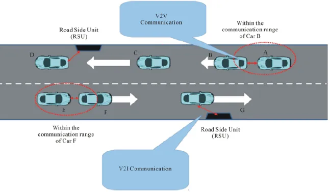
Figure 1.2 Vehicular Ad Hoc Network (V2V and V2I communications) ... 16
Figure 1.3. Layered DSRC architecture in the U.S. ... 17
Figure 1.4. IEEE 802.11 distributed coordination function (DCF) ... 20
Figure 1.5. Safe overtaking in urban roads ... 24
Figure 1.6. Head on collision warning ... 25
Figure 1.7. Intersection Collision Warning [138] ... 25
Figure 1.8. Post-crash notification ... 26
Figure 1.9. Cooperative collision warning due to a stopped vehicle ... 27
Figure 1.10. Illustration of multiuser interfering nodes ... 30
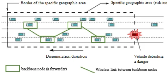
Figure 2.1. Illustration of a backbone in vehicular networks ... 41
Figure 3.1. Illustration of a traffic accident scenario. ... 56
Figure 3.2. Problems experienced by most of the multi-hop broadcasting schemes. (a) –(b) Single forwarder problem (c) Intermediate nodes reachability problem ... 62
Figure 3.3. Network model: (a) Target area structure, (b) Time schedule ... 66
Figure 3.4. Unipolar-orthogonal codes in two adjacent zones ... 68
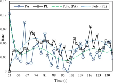
Figure 3.5. Distribution of PA and PL over time in a cell ... 71
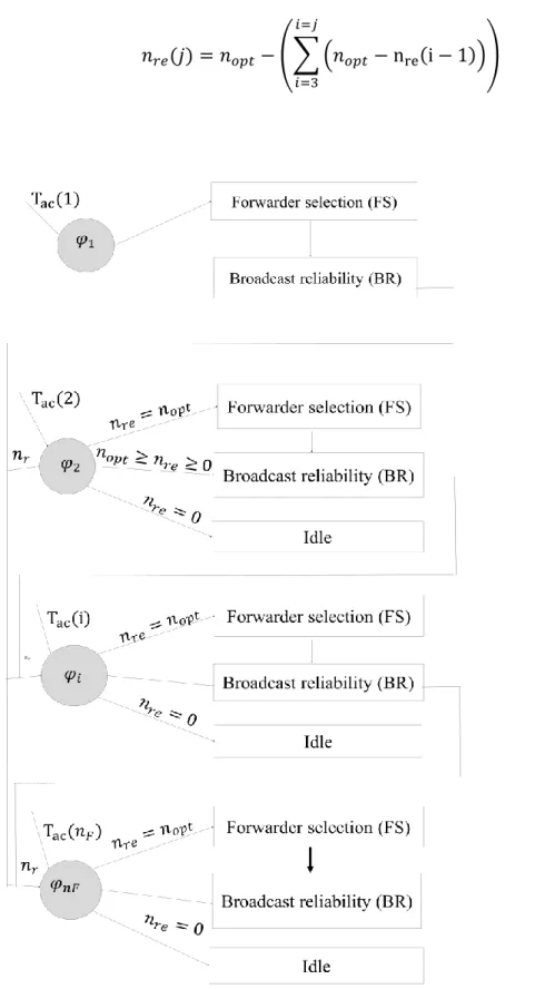
Figure 3.6. State machine of MAC Repetitions Layer (MRL) ... 76
Figure 3.7. State machine diagram of Cooperative reliability ... 80
Figure 3.8. Link reception quality vs. Density ... 83
Figure 3.9. PRR vs. Repetitions ... 84
Figure 3.10. Repetitions nopt vs. density ... 85
Figure 3.11. PRR vs Vehicle density ... 86
Figure 3.12. Delay vs Vehicle density ... 87
Figure 3.13. Network Load vs Vehicle density ... 88
Figure 4.1. Illustration of multiuser interfering nodes ... 91
Figure 4.2. Road segment structure ... 100
Figure 4.3. Cell information (i.e., Beacons reception state) collection during cell transit time. ... 103
viii
Figure 4.6. V-PC algorithm: Step (b): Construction of undirected acyclic graph: Independence test,
Intermediate test (i.e., ordering triangle edges test), Conditional independence test ... 108
Figure 4.7. Link reception quality estimation accuracy vs. training data collection duration ... 118
Figure 4.8. Link reception quality vs. density ... 119
Figure 4.9. PRR vs. repetitions ... 120
Figure 4.10. Repetitions vs. Density ... 121
Figure 4.11. A comparison of Link reception quality estimation for BCRB and REMD vs. vehicle density ... 122
Figure 4.12. PRR vs. Density ... 123
Figure 4.13. Delay vs. density ... 124
Figure 4.14. Network overhead vs. Density ... 125
Figure 5.1. Internet access architecture ... 132
Figure 5.2. Candidate gateways locations ... 135
Figure 5.3. Variation of minimum communication hops ... 144
Figure 5.4. PRR vs. gateways penetration rate: (a) vehicle density: 80 vehicles/kilometer, (b) vehicle density: 120 vehicles/kilometer ... 145
Figure 5.5. Average delay: (a) 80 vehicles/kilometer, (b) 120 vehicles/kilometer ... 147
ix
Table 1.1. Example of vehicular safety applications: communication requirements [5][136] ... 24
Table 2.1. A comparison of emergency message dissemination schemes ... 48
Table 2.2. Comparison between some gateway discovery schemes ... 52
Table 3.1. Simulated multi-hop broadcast schemes ... 81
Table 3.2. Simulation parameters ... 82
Table 4.1. Simulation parameters ... 117
Table 5.1. Simulation parameters ... 142
x
ACK ACKnowledgement
AIFS Arbitrary Inter-Frame Spacing
BCRB Bayesian networks and unipolar orthogonal Code based Reliable multi-hop Broadcast
BN Bayesian Network
BR Broadcast Reliability BSS Basic Service Set
BSSID Basic Service Set Identifier CCH Control Channel
CCI Control Channel Interval CDS Connected Dominating Set
CPF Cooperative Positive orthogonal code-based Forwarding CSMA/CA Carrier Sense Multiple Access/Collision Avoidance CTB Clear To Broadcast
CTS Clear To Send CW Contention Window
DCF Distributed Coordination Function DSRC Dedicated Short Range Communication EDCA Enhanced Distributed Channel Access FCC Federal Communication Commission FS Forwarders Selection
GML Graphical Model Learning GPS Geographic Positioning System
IEEE Institute of Electrical and Electronics Engineers ITS Intelligent Transportation Systems
LLC Logical Link Control LTE Long Term Evolution MAC Medium Access Layer
xi M-HRB Multi-Hop Reliable Broadcast OBU On-Board Unit
OCB Outside the Context of BSS
OFDM Orthogonal Frequency Division Multiplexing
PC Peter-Clark
PDP Packet Delivery Probability PHY Physical Layer
PLCP Physical Layer Convergence Procedure PMD Physical Medium Dependent
POC-MAC Positive Orthogonal Code based MAC PPDU Physical Protocol Data Unit
PRR Packet Reception Rate QoS Quality of Service
REMD Reliable Emergency Message Dissemination RICS Reliable Internet access System
RSSI Received Signal Strength Indication RSU Road Side Unit
RTB Request To Broadcast RTS Ready To Send
SAPF Speed Adaptive Probabilistic Flooding SCH Service Channel
SIFS Short Inter-Frame Space TDC Training Data Collection UPOC Uni-Polar Orthogonal Code V2V Vehicle-to-Vehicle
V2I Vehicle-to-Infrastructure VANET Vehicular Ad hoc Network
xii
My dear parents For your patience, your kindness, and prayers I dedicate this work as a token of my eternal gratitude and my profound respect
xiii
I would like to express my sincere gratitude to my advisor Prof. Abdelhakim Hafid for his patience, support, and understanding throughout the process of writing this dissertation. His valuable feedback and his insightful comments made the completion of this project possible.
Special thanks go to Dear Dr. Pratap Kumar Sahu for his guidance and encouragement during my first years as a Ph. D student. His explanations were easy to grasp and his feedback was highly appreciated.
I am absolutely indebted to my family members who have always unconditionally endured my absence, and provided love, care, and support all the way through.
I would like also to thank all my colleagues at LRC Laboratory for the beneficial discussions and continuous exchange of knowledge.
Last and not least, I would like to thank my friends and community in Montreal. Their support and presence gave me perspective and made the way of performing this work easier to walk.
14
Chapter 1
Introduction
1.1. Introduction
The exponential growth of population and business activities is yielding to severe transportation problems, such as loss of lives (e.g., because of accidents) and traffic congestion. Careful city planning does not scale well over time with an unexpected road usage. Land resources are limited in several countries making it difficult to build new infrastructure (e.g., bridges and highways). More recently, several vehicle safety devices (e.g., seat belts and airbags) have been produced for post-crash live saving goals.
Still, road accidents are considered one of the main causes of death. About 1,700,000 accidents cause over 40,000 deaths and more than 1,300,000 injuries each year in Europe [1]. More than 23% of these traffic fatalities occur due to high-speed, adverse weather and road conditions [1]. To enhance road safety, the recent focus is to provide real time early warning systems (pre-crash warning systems) to alert drivers about dangers ahead. The objective of such systems is to give drivers enough time to undertake early counter measures.
Figure 1.1 depicts a pre-crash warning system. Three vehicles move at speed of 115 km/h (32 m/s) and with an inter-vehicle spacing of 1 s (32 m). If the front vehicle starts hard-braking with deceleration of 4 m/s2, the second vehicle's driver reaction time is 1,5 s (the third vehicle's driver
reaction time is 3s). Without a pre-crash warning, driver 2 and vehicle 3 will slam on the brakes only after seeing the brake lights of the first vehicle, resulting in a 3-vehicle pileup accident. However, employing a pre-crash warning system can reduce (or avoid) the severity of the pileup accident. Indeed, if a warning notification about the hard-braking is conveyed with the minimum possible delay to vehicle 3, such a crash can be avoided [140]. Furthermore, the earlier drivers 2 and 3 are warned of the imminent vehicle crash, the less severe the accidents can be.
15
Figure 1.1. Illustration of a pre-crash warning system [140]
Intelligent Transportation Systems (ITS) using wireless communications and sensors are suggested to improve road safety. Here, roads and vehicles become not only a transportation platform but also a communication platform. Vehicular Ad hoc Networks (VANET) represent the key technology of ITS by enabling wireless communication among vehicles; indeed, it has been reported that VANETs have the potential to address more than 79% of all crashes involving unimpaired drivers. In VANET, every vehicle is equipped with a wireless communication device that enables Vehicle-to-vehicle (V2V) communication and Vehicle-to-Infrastructure (V2I) communication. Both V2V and V2I communications are standardized by the dedicated short-range communication DSRC standard [2].
The rest of the chapter is organized as follows. Section 1.2 presents V2V and V2I communication modes, the DSRC standard in the U.S, characteristics of VANETs and a sample of applications that can be implemented in VANETs. Section 1.3 describes our motivation and problem statement. Section 1.4 presents thesis contributions. Section 1.5 presents thesis organisation.
16
1.2. Vehicular Ad Hoc Networks
1.2.1. V2V and V2I communication modes
VANET architecture supports V2V and V2I communications. V2V communication allows the communication among neighboring vehicles. V2I communication allows the communication between vehicles and fixed roadside units (RSUs). RSUs are installed at fixed roadside locations. Each vehicle is equipped with a wireless communication device, called an on-board unit (OBU), to form wireless communication links between vehicles (or RSUs). Hence, OBUs communicate with other neighboring OBUs or with neighboring RSUs. RSUs have higher radio coverage than vehicles. One of the main benefits of RSU infrastructure is to relieve poor network connectivity (e.g., RSUs can increase the overall coverage of a vehicular network and enhance network performance (i.e., delay) between disconnected vehicles) [8]. RSUs are connected to the Internet via either wireline or wireless networks. In addition, by establishing connection with an RSU, a vehicle can access the Internet (see Figure 1.2).
17
The radio communication range varies based on the transmission power of the transceiver [2]. The maximum radio communication range of an OBU device is smaller than 1 km. If a message needs to be disseminated to nodes2 beyond the radio range, blind flooding (i.e., every vehicle
within a target area for message transmission retransmits the message) extends the radio coverage range of a node by multi-hop links. In dense networks, flooding degrades considerably the network performance (e.g., due to high packet collisions). The alternative techniques are non-flooding. These techniques, called message dissemination, allows only some vehicles, called “forwarders”, to retransmit the message, which is reviewed in Chapter 2 of this dissertation.
1.2.2. DSRC Overview
Dedicated Short Range Communication (DSRC) [2] is the emerging wireless technology for communication between OBUs and RSUs. The term “Dedicated” refers to the fact that the Federal Communications Commission (FCC) in the U.S, allocated 75 MHz of licensed spectrum in the 5.850–5.925 GHz frequency band, for vehicular communication [3]. The term “Short Range” conveys that communication takes place over short range radio links (i.e., hundreds of meters). The primary motivation for DSRC deployment is crash-prevention. DSRC frequency band is divided into one Control Channel (CCH) and six Service Channels (SCHs). Safety messages are exchanged on CCH. Figure 1.3 shows the protocol stack for DSRC communication in the U.S.
Figure 1.3. Layered DSRC architecture in the U.S.
2 Nodes designate either vehicles or RSUs
802.11p 802.11p 1609.4 LLC IEEE 802.2 IPv6 TCP/UDP HTTP 1609.1 WSMP 1609.3 1609.2 Security Physical layer MAC layer (MAC) LLC layer Network layer Transport layer Application layer
18
At the Physical (PHY) layer and medium access control (MAC) layer, DSRC uses IEEE 802.11p which is a modified version of IEEE 802.11 (WiFi) standard. In the next subsections, we present the DSRC Physical (PHY) layer and the DSRC Medium access control (MAC) layer.
1.2.2.1. Physical Layer
The physical layer of IEEE 802.11p is similar to IEEE 802.11as, with some adaptations for VANET characteristics. DSRC/IEEE 802.11p PHY reduces the signal band from 20MHz to 10MHz. As a result, the values of physical parameters (e.g., guard interval and duration of a data symbol) for IEEE 802.11p are doubled compared to the IEEE 802.11a PHY. The DSRC PHY protocol is defined in IEEE 802.11. The physical layer protocol is divided into two sublayers: the physical medium dependent (PMD) sublayer and the physical layer convergence procedure (PLCP) sublayer. PMD interfaces directly with the wireless medium. It uses the familiar orthogonal frequency division multiplexing (OFDM) technique, which was originally added to 802.11 in the 802.11a amendment. PLCP defines the mapping between the MAC frame and the basic PHY layer data unit. In a transmitter, PLPC processes the bytes in a MAC frame in order to be transmitted into OFDM symbols for transmission over the air by PMD. PLPC adds PHY layer overhead to the MAC frame to create the PHY Protocol Data Unit (PPDU). The MAC sublayer passes 3 parameters to PLPC: (1) length of the MAC frame; (2) transit data rate; and (3) transmit power. In a receiver, PLPC performs the inverse function to extract the MAC frame from PPDU. Furthermore, PLPC provides the received signal strength interference (RSSI). When PLPC requests PMD to transmit a frame, the PMD sublayer performs the OFDM modulation and transmits PPUD over the air. The PMD receiver performs the demodulation. The PMD sublayer passes RSSI with the received frame up to the PLPC sublayer. At the receiver, 802.11p does not modify the sensitivity requirement which is a function of the data rate of the packet. For 10 MHz, minimum sensitivity levels vary from -85 dBm at 3Mb/s to -68dBm at 27Mb/s. DSRC on 10 MHz channels is more suited to delay and Doppler effects in a vehicular environment.
1.2.2.2. MAC Sublayer
The MAC layer of IEEE 802.11p is based on IEEE 802.11a. Particularly, for V2V, DSRC defines a new type of 80211 communication, Outside the Context of a Basic service set (OBC), to cope with VANET high mobility (e.g., short-duration communication link in case of two
19
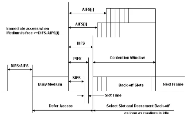
vehicles with opposing driving directions). OBC does not require neither authentication nor association when exchanging data frames. To distinguish frames sent in OCB mode, 802.11p sets the value of Basic Service Set (BSS) identifier (BSSID) field in the data frame header to 0xFFFFFF, also known as wildcard value. IEEE 802.11p utilizes the Enhanced Distributed Channel Access (EDCA) mechanism to provide service differentiation. The basic mechanism of sharing the medium between vehicles relies on the Distributed Coordination Function (DCF) of CSMA/CA. IEEE 802.11p does not alter CSMA/CA rules in the 802.11 [2] (the principles of "carrier sensing" and "collision avoidance"); carrier sensing is achieved through Clear Channel Assessment (CCA) and/or Network Allocation Vector (NAV). Collision avoidance is achieved using a back-off procedure. In a simplest communication scenario under CSMA/CA, if a vehicle has a frame to send, it first senses the wireless medium for Distributed Inter-frame Space (DIFS). If the medium is idle, the vehicle begins transmission of its frame. If the medium is busy, the vehicle performs a random back-off to wait before transmission. The countdown begins when the medium becomes idle. The above mechanism applies to both broadcast and unicast frames. Besides, EDCA enables 4 Quality of Service (QoS) classes by prioritizing data traffic within each node. Hence, each node maintains four queues. These queues have different Arbitrary Inter Frame Spacing (AIFS) and different back-off parameters; the higher the priority, the shorter AIFS. Each transmission queue of an Access Category (AC) operates as an independent DCF station (STA). Figure 1.4 shows the basic channel access procedure in DCF. Basically, in unicast communication, the sender transmits a packet and waits for an acknowledgment (ACK). If no ACK is received, a back-off procedure is invoked before a retransmission is allowed. For every attempt to send a packet, the size of the contention window (CW) is doubled from its initial value (CW min) until a maximum value (CW max) is reached. This enables to separate the nodes
that want to send at the same time. After a successful transmission (or when the maximum number of channel access attempts is reached), the contention window is reset to its initial value. Furthermore, vehicles can employ RTS/CTS control packets handshake to combat the hidden terminals problem. However, in broadcast communication, a frame is not acknowledged and is sent only once.
20
Figure 1.4. IEEE 802.11 distributed coordination function (DCF)
Besides, broadcast frames cannot use the RTS/CTS handshake making them prone to the hidden terminal problem. EDCA/DCF lacks deterministic QoS guarantee for broadcast communication. This issue is investigated in Chapters 3 and 4.
1.2.3. VANET characteristics
In this Section, we start by describing radio propagation issues, in urban vehicular networks (e.g., presence of buildings), and interferences; then, we present key characteristics of vehicular networks.
Radio propagation
Here, we consider direct communication between one transmitter and one receiver. The characteristics of radio signals change over time and space. Signal propagation is influenced by three basic physical phenomena [139]:
(a) Reflection, which occurs when a wave hits an object of very large dimension compared to the wavelength of the wave. These objects can be buildings or walls. If a wave is reflected, it changes its direction;
21
(b) Diffraction, which occurs if a wave hits an object that has sharp irregularities (e.g., building edges). In this case, many secondary waves occur that continue propagating;
(c) Scattering, which occurs if the propagation medium contains a high number of objects that are small compared to the wavelength, e.g., street signs. These objects split the wave into several ones. At the receiver, several of the waves arrive and they interfere with each other resulting in interferences between different propagation paths of one transmitted signal [139]. These effects are caused by the physical environment (e.g., frequency, distance, antenna heights, atmospheric conditions, and the presence of buildings) in which the signal propagates. To describe these effects on the signal, three types of radio propagation models are used [139]: (i) large-scale path loss; (ii) shadowing or large-scale fading; and (iii) small-scale fading. A possible way to describe the reception characteristics of a signal lies in subsequently applying mathematical descriptions of the three models to the transmitted signal: first, the signal attenuation due to the path loss is calculated, then, shadowing effects are added, and finally, the effects of fading are applied [139].
Interference
Here, we consider multiple transmissions in the network. Basically, there are two sources of interference on a communication channel from the perspective of a receiving node (We focus on the common control channel (CCH)): (a) Multi-path interference; and (b) Multi-user interference.
Multi-path interference is the fact that a transmission follows multiple paths, as explained in the previous paragraph.
Multi-user interference is the fact that multiple transmissions overlap on the same channel [139]. Multi-user interference occurs for two main raisons: (a) two senders that are geographically close to each other (in the radio ranges of each other) access the channel at the same moment in time. This interference can be mitigated using medium access schemes that are based on CSMA/CA. Indeed, using CSMA/CA, the channel may be accessed only if a node that wants to transmit a message does not sense any other transmission on the channel (see Section 1.2.2.2 for details about the EDCA/DCF scheme). The use of a random number of back-off slots reduces the probability that two senders that are geographically close to each other access the channel at the same moment. However, the back-off procedure cannot ideally avoid such simultaneous access
22
in broadcast transmission, resulting in collisions. This phenomenon is serious in multi-hop broadcasting that uses flooding (see. Section 2.2 of Chapter 2 for more details). Non-flooding techniques in consequence reduce the number of transmitters (forwarders) which can reduce probability of transmitting on the same slot; and (b) hidden terminal, defined as the access to the channel during the transmission of another packet. Hidden terminal is the primary cause of multi-user interference. Indeed, the CSMA/CA decides on whether the channel is in use or not by measuring the signal power on the wireless channel. The received power may become low over distance due to path loss (In chapter 3, we provide a method to compute signal power attenuation rate caused by background traffic at each receiver and we find out that this rate is proportional to the packet collision rate that occurs at same receiver). As a result, a node may sense the channel idle while another transmission that has a low reception power is ongoing at the specific receiver. The node, thus, decides to transmit although there is an ongoing transmission resulting in collision at a receiver positioned between the two transmitters [139].
Mobility
VANET is a highly dynamic and mobile environment. Vehicles have mobile characteristics (i.e., each driver has its own moving way to reach an individual geographical location). Yet, the degree of freedom is limited by the road network, traffic rules and the behavior of other vehicles on the same road. The mobility of nodes affects communication, as radio propagation characteristics and network topology continuously change [139].
Distributed decentralized system
In VANET, a huge number of mobile vehicles and stationary RSUs participate in the communication. Such a communication system is distributed and decentralized. Hence, a centralized control that provides management and coordination functionality is not possible. Instead, immediate and direct communication among all nodes is established and provided in a decentralized manner. Such a decentralized control leads to interferences of uncoordinated transmitters [139].
Broadcast communication
Data traffic generated by safety applications is broadcast traffic. Broadcast means that the transmitted data (e.g., crash warning) is not addressed to one specific vehicle, but to all vehicles positioned in the surrounding of the transmitter. The challenge of data dissemination/broadcast
23
is that a reception by every node within a specified surrounding cannot be guaranteed as there is no suitable way to acknowledge the reception of broadcast messages. Even if acknowledgement schemes are used, it will not be possible to ensure that every possible receiver gets the message. This is due, in part, to the fact that there is no information on how many nodes are potential (good) receivers. Consequently, reliability of transmissions cannot be guaranteed for broadcast communication. This makes the impact of interference even more severe in broadcast transmissions.
1.2.4. VANET Applications
This section overviews vehicular applications, several user cases and their associated QoS requirements. ITS applications can be classified into three categories: (a) road safety applications; (b) traffic efficiency and management applications; and (c) infotainment applications.
1.2.4.1 Road Safety Applications
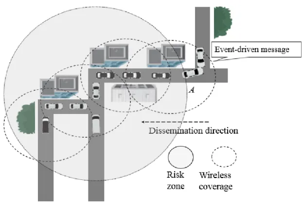
Safety applications are employed to decrease the probability of crashes. The U.S. Vehicle Safety Communications Consortium has identified more than 75 application scenarios enabled by DSRC [4]. These applications can be accomplished by sharing, between vehicles and RSUs, (a) periodic messages (also called beacons): they are preventive safety messages used, for example, to predict collisions. Note that beacons can be also used by non-safety applications (e.g., road traffic control). Exchange of beacons makes vehicles aware of their environment; indeed, beacons contain information about the state of the sending vehicle (e.g., position, direction, and speed); and (b) event-driven messages (also called emergency or safety messages): they are generated due to the detection of unsafe situations (e.g., a car crash). More specifically, a vehicle generates an emergency message on detecting a danger. A vehicle is defined as the source node when it detects the danger on the road. The emergency message should be delivered to all nodes in the target area, also called risk zone3, exposed to the potential danger as quickly
as possible. The risk zone is extended behind the source vehicle along the road. All vehicles in the risk zone should be notified ahead of time, before they reach the potential danger location, to allow them to take action in time (e.g., slow down or brake). Emergency messages are
24
disseminated in a broadcast fashion since their content is beneficial to all vehicles in the risk zone. Safety applications have strict reliability and delay requirements (See Table 1.1).
Table 1.1. Example of vehicular safety applications: communication requirements [5][136] Safety application Transmit mode Range Max. Latency
(ms)
Reliability requirement
Over taking vehicle warning Periodic ≤ 250 1000 High
Head on collision warning Periodic ≤ 250 200 High
Intersection collision warning Event-driven ≤ 300 100 High Post-crash Notification Event-driven ≤ 300 500 High Cooperative collision warning Event-driven ≤ 300 100 High In the following, we present some examples of safety applications and their use cases.
Overtaking vehicle warning (OVW)
OVW [137] [138] aims at preventing collision between vehicles in an overtake situation, in urban roads. A possible use case of OVW application is depicted in Figure 1.5; vehicle 1 is willing to overtake vehicle 3. A Powered Two Wheeler (PTW) 2 is already doing an overtaking maneuver on vehicle 3. Collision between vehicle 1 and PTW 2 is prevented when PTW 2 informs vehicle 1 to stop its overtaking procedure. This situation is critical for PTW users due to blinds spots and differential of speed between PTW and a car which does not allow the driver to be aware of the presence of a motorcyclist. The purpose behind this use case is to avoid collision between PTW and vehicles by giving a warning to the vehicle.
.
25
Head on collision warning (Do Not Pass Warning)
DNPW [137] [138] reduces the risk of a head collision by sending early warnings to vehicles that are traveling in opposite directions. This use case is also denoted as “Do Not Pass Warning”. As shown in Figure 1.6, vehicle 1 attempts to overtake vehicle 3 which obstructs the driver's 1 field of view, while vehicle 2 is approaching from the opposite lane. The purpose behind this use case is to warn the driver of vehicle 1, of an incoming vehicle in the adjacent lane. Thus, vehicle 1 needs to delay or abort the overtaking manoeuvre. This allows to avoid accidents linked to head on collision situations.
Figure 1.6. Head on collision warning Intersection collision warning (ICW)
ICW [137] [138] aims at reducing the risk of lateral collisions for vehicles that are approaching road intersections. The danger is detected by vehicles or RSUs. The information is signaled to the approaching vehicles in order to lessen the risk of lateral collisions. Figure 1.7 depicts an example of the Intersection Safety application.
26
A crash happens at an intersection creating a dangerous situation. Now, drivers approaching this intersection will be warned about the crash. The purpose of this use case is to avoid critical situations resulting from an accident beforehand. Intersections are probably the most complex part of road infrastructures and places where collisions can result in serious injury or death. An accident at an intersection can result in other accidents as an unforeseen situation would exist. At intersections, traffic-flow is very complex. Hence, the driving behaviour of other drivers could change immediately, due to such unforeseen situations [138].
Post-Crash Notification (PCN)
In PCN [137], a vehicle involved in an accident would broadcast warning messages about its position to trailing vehicles (in the risk zone) so that they can take decision with time in hand. The PCN application may be implemented using both V2V and V2I. V2V has the advantage of transmitting quickly the information through a discover-and-share policy. Using specific sensors, PCN consists of measuring possible changes in the rational behavior of the driver (e.g., quick brake use, rapid direction changes, and so on), which are then communicated back to other vehicles along the same direction (See Figure 1.8).
Figure 1.8. Post-crash notification
Cooperative Collision Warning (CCW)
CCW [137] [138] is a wireless communication based collision warning. Especially, CCW is supposed to allow warning in the context of road geometry changes (i.e., road curves). CCW has advantages over In-vehicles sensor warning systems which are expensive, or even useless, in some situations (i.e., road curves). CCW provides warnings to drivers based on the motions of neighboring vehicles. Indeed, each vehicle, through GPS, is able to estimate its location relative to surrounding vehicles. Such an information
27
enables to alert and warn drivers of impending threats (i.e., a stopped or slow-moving vehicle before arrival at the curve) without the use of sensors. A V2V cooperative safety system is, then, formed to forward collision warning. A typical CCW use case is depicted in Figure 1.9. Before arriving to the curve, vehicle 2 can detect a stopped car while driving (V1). This can be done by estimating the relative distance. Not so different from PCN, the information is flooded to the vehicles in the risk zone. Note that CCW is set up only in a V2V communication mode.
Figure 1.9. Cooperative collision warning due to a stopped vehicle
In situations where the maximum radio communication range does not reach the intended distance, message dissemination using multi-hop broadcast is necessary. This will be addressed in Chapters 3 and 4.
1.2.4.2. Traffic efficiency and management
Traffic efficiency and management applications focus on improving traffic flow. Speed Management (SM) applications [5] assist drivers in managing the speed of their vehicles to avoid unnecessary stopping. Cooperative Navigation (CN) applications [5] aim to manage the navigation among vehicles, like platooning. Congestion Road Notification (CRN) applications [5] detect and notify drivers about road congestions; CRN is used for route and trip planning. It evaluates new routes when heavy congestion is detected on a route or a portion of it.
28
1.2.4.3. Infotainment applications
The aim of infotainment applications is to offer comfort to drivers and/or passengers. In modern cities, people spend a considerable amount of time commuting by car from one place to another. A plethora of infotainment applications [6] are made available to vehicular users anytime and anywhere. This calls for vehicular networks to provide Internet access to vehicles. Infotainment applications include content download, media streaming, VoIP, social networking, gaming, cloud access, etc. Infotainment applications will be offered to passengers using service channels. A number of these applications is based on delay-sensitive video streaming requiring real-time transmission. To enhance the end-user experience, parameters such as frame rate, frame dropping, and timeliness are the basis of a good video quality. Hence, infotainment applications require low end-to-end delay and high reliability (low packet loss). More details about QoS support in infotainment applications can be found in [7] [8] [9].
Internet Access
In-vehicle Internet access [10] allows a vehicle to connect to the Internet (e.g., to use infotainment applications) through an Internet gateway. Typically, a vehicle connects to an Internet gateway in its vicinity. In case no Internet gateway in the range, a vehicle relies on multi-hop communications to connect to an Internet gateway beyond its transmission range. An Internet gateway discovery protocol is, then, required to discover routes (i.e., an established route is a fixed succession of nodes between the source and the destination) to Internet gateways not in the range. Internet service providers (ISPs) offer Internet access through various wireless technologies (i.e., LTE) using Internet gateways. Once connected to Internet, a vehicle can access Internet services (i.e., email). In the following, we briefly describe Internet gateways as well as the gateway discovery/advertisement process.
Internet gateway
Traditionally, an Internet gateway is an RSU, installed in fixed position along a roadside [36]. Unfortunately, Internet access through RSUs requires pervasive RSUs to ensure each vehicle is in RSU’s transmission range [11] (i.e., the typical range of an RSU is few hundred meters). Such a requirement incurs high infrastructure deployment cost. Several research efforts [12][13][14][15][16] are proposed to optimally place RSUs. Indeed, deploying a new RSU needs intensive investigation [11]; for instance, the land where to place a new RSU may be private requiring owner permission. It may be difficult, if not impossible, to get such a permission.
29
Therefore, deploying new RSUs often requires a large amount of investment and elaborate design, especially at the city scale. Consequently, Internet access systems that rely only on roadside infrastructure are impracticable to be implemented. Recently, the concept of long-term evolution (LTE)-connected vehicles [17] (i.e., a vehicle equipped with 802.11p and LTE interfaces) has received a lot of attention. Once in the range of a LTE base station, the vehicle gets Internet access. Actually, LTE provides a robust mechanism for mobility management of vehicles [18] (i.e., supports data rate of 10 Mbps with speed up to 140 km per hour). LTE also fits the bandwidth demands and the quality of service requirements of infotainment applications [18]. However, mobile data is experiencing explosive growth [19]; this makes LTE cellular infrastructure bandwidth not able to keep up with connecting high number of connected vehicles [20]. Also, it has been reported that cellular infrastructure connectivity cannot evolve once it is installed [17]. Furthermore, many vehicles incur frequent handoffs, because of high mobility, requiring higher bandwidth [21]. Hence, allowing only some connected vehicles to operate as Internet gateways (mobile Internet gateways) to other vehicles may be effective [22]. Various Internet access systems using connected vehicles as Internet gateways [23] [24] [25] [26] have been proposed. Getting Internet access through either RSUs ([12] [13] [14]) or connected vehicles ([23] [24] [25] [26]) relies on multi-hop communication links [36].
Gateway discovery/advertisement
Gateway discovery/advertisement is the process of finding a gateway that matches the requirements of requestors (i.e., vehicles). Conventionally, an Internet gateway periodically advertises its services (i.e., broadcasts an advertisement message) to announce its presence in either one-hop or multi-hop area using flooding. Furthermore, a requester (vehicle), in turn, discovers and selects gateways using a gateway discovery scheme; the requestor sends discovery messages, in the network to establish a route to a convenient gateway. Route discovery process relies on multi-hop broadcasting to find an appropriate Internet gateway. Existing gateway discovery/advertisement schemes are reviewed in Chapter 2.
1.3. Motivations and Problem statement
V2V and V2I communications are expected to enable diverse safety and infotainment applications. IEEE DSRC/802.11p is the emerging communication standard for vehicular communication. Broadcast is the preferred communication mode for vehicular applications.
30
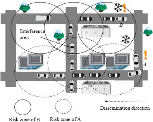
In big cities, several emergency events have to coexist together to achieve life-saving goals. On detecting an unexpected event (i.e., a traffic accident), a vehicle immediately issues an event-driven message to notify neighboring vehicles/drivers ahead of time to allow them to take action in time. Conceived to be just up to few hundred meters [27], an emergency message has to be forwarded hop-by-hop to far-away vehicles (in the risk zone). Figure 1.10 shows a scenario of hazardous driving conditions on adjacent road segments.
Figure 1.10. Illustration of multiuser interfering nodes
Vehicle A (involved in a crash) broadcasts an emergency message 𝑀𝐴 to the vehicles in the risk zone of A. Vehicle B (involved in a crash) broadcasts an emergency message 𝑀𝐵 to the vehicles
in the risk zone of B. On receiving a message, a vehicle can slow down/brake to avoid hitting the car(s) it follows. A single uninformed vehicle, may result in terrible causalities [27][28][29][30]. The successful dissemination of emergency messages makes a difference between life and death. Thus, no driver should be deprived of information about emergency events. Broadcast-based emergency message dissemination needs timely and lossless medium access. Consequently, high
31
reliability of message dissemination is required (e.g., the probability of packet reception should be greater than 0.99 [29]).
Infotainment applications call for vehicular communication networks to support Internet services in vehicles [31]. Indeed, In-vehicle Internet access [10] allows a vehicle to connect to the Internet through an Internet gateway. Traditionally, an Internet gateway is RSU, installed at fixed position along a roadside. Recently, the concept of LTE-connected vehicles [17] (i.e., a vehicle equipped with 802.11p and LTE interfaces) has received a lot of attention. Once in the range of a LTE base station, the vehicle gets Internet access. Allowing some connected vehicles to operate as Internet gateways (mobile Internet gateways) to other vehicles may be effective [22]. Getting Internet access through either RSUs ([12] [13] [14]) or connected vehicles ([23] [24] [25] [26]) relies on multi-hop communication links. Typically, a vehicle connects to a gateway in its vicinity. In case no Internet gateway in the range, a vehicle relies on multi-hop communications. To do so, an Internet gateway discovery scheme is required to discover routes (i.e., an established route is a fixed succession of nodes between the source and the destination) to Internet gateways not in the range. Internet gateway discovery schemes should be enable the establishment of reliable paths to Internet gateways. The discovery process can be done in two ways: (1) a gateway periodically sends advertisement messages; or (2) a requestor sends discovery messages. If some nodes along the path have low reception probability, the communication would be stopped.
Nevertheless, many factors can influence probability of successful message reception in wireless communications. In vehicular networks, vehicles share a common wireless channel by using the same radio frequencies. Each node competes for channel access when it needs to transmit, without any guarantee of success. Typically, several factors reduce probability of successful message reception in wireless communications. Random loss is caused by lossy wireless channels and node mobility. In city road networks, severity of interfering nodes increases (i.e., overhearing a packet not intended for the receiving node is considered as interference) [29] [30]. Vehicles may receive signals from other vehicles on adjacent streets. Both periodic messages (i.e., beacons) and emergency messages [30] are transmitted on CCH. Beacons increase the severity of interfered/collided packets. Furthermore, high mobility of vehicles makes reliability of communication in vehicular networks more complex [27].
32
Despite DSRC/802.11p based broadcast has the potential to provide low latency in one-hop [28], it is reported to be defective in terms of reliability making it a major reason that hinders the deployment of IEEE DSRC/802.11p [32]. IEEE DSRC/802.11p defines the MAC layer to be based on CSMA/CA [32] with minor modifications. The channel access mechanism of DSRC/80211p is Enhanced Distributed Channel Access (EDCA); it is not able to provide predictable reliability for safety services. As a result, IEEE DSRC/802.11p MAC is not able to guarantee broadcast reliability. More specifically, 802.11p MAC does not implement any broadcast reliability mechanism [33] (e.g., DSRC/802.11p-based broadcast does not support acknowledgement [32]). Comparing broadcast to unicast, no mechanism is used to alleviate the hidden terminal problem (i.e., virtual carrier sensing is not used in IEEE 802.11 broadcast [32]). Hence, the current draft of IEEE 802.11p MAC [34] [35] cannot meet strict reliability requirements (e.g., 99%).
In multi-hop broadcasting, the probability of successful message reception decreases with the number of hops [36]. Forwarder selection increases the probability of collisions/interference [28] [33]. IEEE 802.11 MAC does not offer any specific support to improve reliability in multi-hop, apart from the naïve flooding scheme [38]. However, such a solution may lead to the broadcast storm problem [39] resulting in unreliability (i.e., high packet loss) and delayed communication [39].
Thus, the objective of this dissertation is to contribute to the design and the evaluation of new solutions that ensure efficient safety message dissemination (multi-hop communications) for urban vehicular applications considering QoS requirements (i.e., delay and reliability). On one hand, this work proposes two new emergency message dissemination schemes that provide best reliability, compared to existing schemes, while satisfying delay requirements of safety applications. On the other hand, it proposes and evaluates, an Internet access scheme that provides Internet access to vehicles considering delay and reliability in order to enable infotainment applications.
The first 2 contributions of this thesis address the problem of emergency message dissemination, in urban VANETs, considering the requirements of safety applications in terms of reliability (packet reception rate) and delay. In the literature, several approaches have been proposed to deal with this issue. Among them, Several CSMA-based multi-hop broadcast schemes have been proposed (e.g., [60][33][26][61][42][43][44][45]). Despite their good
33
performance in low density network, exiting schemes sustain major shortcomings in urban environment. On one hand, in fast schemes (e.g., [60][33][26][61][62]), the emergency message is forwarded to selected forwarders in quick successions. However, in case the forwarder has moved away or is malfunctioning, the multi-hop communication would not be possible. Efficient schemes [42][43][44][45], on the other hand, propose techniques to mitigate the broadcast storm problem. However, these schemes don’t consider MAC layer issues in their forwarding node selection mechanism yielding to unreliable transmissions. They use control packet exchange and/or acknowledgement packet and select a single forwarding node at each hop. DSRC/802.11p-MAC [32] can’t characterize/detect random access events resulting in unreliability. In harsh network conditions, a sender does not know whether its transmitted message is successfully received or not. Recently, repetition-based broadcast MAC schemes (e.g., [46][48]) have been proposed to enhance broadcast reliability for safety applications. The basic idea is to repeat (i.e., transmit) the message multiple times within a frame in order to increase reception probability; a frame consists of L time slots. Random repetitions schemes like SFR [46] and AFR [46] randomly select repetition slots. It has been proved that selecting k slots out of L raises the probability of successful message reception [46]. Expanding upon this finding, structured repetitions are proposed to further protect repeated packets from hidden terminal problem [49]. Positive Orthogonal Codes (POC), known as Uni-Polar orthogonal codes (UPOC) [47], as structured repetition patterns, have been reported to suppress hidden terminal problem [49]; an UPOC is a binary code of fixed length L, where cross-correlation between any pair of code-words is less than a given value [49]. However, without evaluating the channel condition, if fixed number of messages is forwarded within frame, we may be sending either too few or too many packets. Too many packets may lead to considerable overhead and too few packets may lead to unreliability. It is important to note that most existing Repetition-based MAC schemes [46][48][49] are not compatible with emerging DSRC/802.11p [32].
The third contribution focuses on the problem of providing Internet access in urban vehicular environments considering reliability and delay. Several Internet gateway discovery schemes (i.e., [50][26][51][52]) have been proposed in the literature. These schemes can be classified into three categories: (1) Proactive approaches: Internet gateways advertise themselves in the whole network; (2) Reactive approaches: vehicles that want Internet access, need to flood the network for Internet gateway discovery; and (3) Hybrid approaches: Internet gateways advertise
34
themselves to their neighbors (1 or n hops away); then, requesters send packets to find an Internet gateway in these advertisement areas. Despitetheir good performance in 1-hop, existing schemes (e.g., [26][51][53][54]) make use of link stability metric, which is based only on mobility metrics (e.g.,relative motion between neighboring vehicles, speed, etc.), to determine paths to Internet gateways. In city settings, such a selected route can be broken frequently owing to the high mobility of vehicles. Any node that ensures progress toward the destination can be used for forwarding. The forwarding decision is based on the position of destination vehicle and position of one hop neighbors. However, the link to the selected node may be unreliable in harsh network conditions leading to packet loss. From above discussions, we can conclude that the route discovery schemes do not guarantee reliable communication, in city settings.
1.4. Thesis Contributions
The thesis consists of three contributions: (1) a reliable multi-hop broadcast scheme, called Reliable Emergency Message Dissemination scheme (REMD), suitable for a wide range of vehicular safety applications; (2) a new multi-hop broadcast scheme, called Bayesian networks and unipolar orthogonal Code based Reliable multi-hop Broadcast (BCRB); and (3) an Optimal Gateway Placement and Reliable Internet Access in Urban Vehicular Environments, called reliable multi-hop Internet access system (called RICS) for urban vehicular environments.
In the first contribution, we propose REMD which is compatible with IEEE DSRC/802.11p. Basically, REMD divides the target area into multiple cells (fine-grained vehicle positions) to form adjacent grid-like zones. REMD consists of 5 proposals (1) a curve-fitting and polynomial extrapolation based scheme to estimate, with good accuracy, the reception quality of link (in each cell) in the transmission range of the sender; (2) a Max-Min optimisation problem and its resolution that allows to determine an optimal number of repetitions (i.e., message transmissions) to satisfy 1-hop reliability requirements. The problem resolution consists of calculating packet reception rate (PRR) using exact Poisson’s binomial distribution. In urban vehicular networks, Poisson’s binomial distribution does not follow an asymptotic Poisson distribution. We turn to find the exact formula of probability mass function (p.m.f) of the distribution using a Fast Fourier transform (FFT) based algorithm, labeled PMF-FFT. The time complexity of PMF-FFT is 𝑂(𝑛 × log(𝑛)), where n is number of cells. The input to the optimization problem is link reception qualities computed in (1); (3) a UPOC-based scheme that carefully generates repetition patterns
35
to minimize/avoid interferences between senders (vehicles) located on different road segments; (4) a scheme that selects appropriate forwarders, at each hop, with the objective to satisfy multi-hop reliability requirements. These forwarders, at each multi-hop, cooperatively repeat the message (based on the number of repetitions computed in (2) and repetition patterns determined in (3)) to support reliability requirement in next hop; and (5) a sub-layer between MAC and LLC responsible for generating broadcast repetitions. Simulations validated REMD (the analytical model) and did show its outperformance compared to existing schemes in terms of reliability, end-to-end delay and network load.
In the second contribution, we propose BCRB which is compatible with IEEE DSRC/802.11p; it focuses on the main limitations of the first contribution: (1) link reception quality estimation: BCRB proposes a Bayesian networks based scheme to estimate, with good accuracy, link reception quality, at different locations in the zone covered by the transmission range of the sender. This estimation is based on executing a training data collection phase (TDC) that exploits beacons periodically generated by vehicles. To learn the Bayesian network, we make use of a modified version of PC [111] algorithm, called V-PC, together with the Expectation Maximization (EM) [116] algorithm. We make use of a graph indexing method to execute V-PC in 𝑂(𝑛), where n is number of cells; and (2) Optimal number of repetitions: BCRB proposes a more accurate resolution of the Max-Min optimisation problem that allows determining an optimal number of repetitions (i.e., message transmissions) to satisfy 1-hop reliability requirements for each receiver in transmission range. More specifically, BCRB guarantees broadcast reliability for each receiver in the zone covered by the transmission range of the sender using a combination of packet delivery probability (PDP) and packet reception rate (PRR) metrics. Simulations validated our scheme (the analytical model) and did show its outperformance compared to existing schemes in terms of reliability, end-to-end delay and network load. Furthermore, simulations did show that both REMD and BCRB successfully provide assured reliability while satisfying end-to-end delay requirements of safety applications. BCRB could achieve less end-to-end delay and network load compared to REMD for all vehicle densities. Also, BCRB outperforms REMD in terms of link reception quality estimation accuracy especially in low vehicle density.
In the third contribution, we propose RICS for urban vehicular environments that uses our proposed BCRB. We make use of both LTE-connected vehicles and the already deployed RSUs
36
infrastructure as Internet gateways. Indeed, RSUs have a considerable impact on network reliability, as they are fixed reliable nodes [55]. Because of random mobility of vehicles, there is the possibility of network fragmentation. Static RSUs may act as bridges between fragmented groups of vehicles [11]. LTE-connected vehicles enhance Internet gateways availability because adding such vehicles (e.g., buses and taxis) doesn’t require additional infrastructure (e.g., land). In [22], it has been reported that using connected vehicles as Internet gateways increases the probability, for moving vehicles, to set up paths with fewer hops. To ensure reliable multi-hop In-vehicle Internet access, we determine minimum possible communication hops, from a requesting vehicle to a fixed/mobile Internet gateway, with high reliable advertisement message dissemination. To accomplish this, we model the Internet gateways placement problem (called GP) as a 2-dimentional k-center [56] optimization problem. This problem is known to be NP-hard. We make a dimension reduction of the optimization problem and propose an exact time resolution algorithm 𝑂(𝑛2 × log(𝑛)), where n is number of vehicles, to solve it. In addition to
computing minimum communication hops, we implement an Internet gateway discovery protocol (using BCRB) which exploits the reception quality of 802.11p wireless links to establish high reliable communication paths. Simulations did show that RICS outperforms existing schemes in terms of reliability, end-to-end delay and network load.
1.5. Thesis Organization
The rest of this thesis is structured as follows. In Chapter 2, we describe existing approaches in the literature that address the aforementioned issues (i.e., emergency message dissemination and Internet gateway discovery/advertisement process in vehicular network). Chapter 3 presents REMD. Chapter 4 describes BCRB. Chapter 5 presents RICS. Chapter 6 summarizes the major contributions of this dissertation and outlines few/possible future research directions.
37
Chapter 2
Related work
2.1. Introduction
IEEE DSRC/802.11p based broadcast is the preferred communication mode for vehicular applications. Several safety applications forward emergency messages hop-by-hop to vehicles in the risk zone. Infotainment applications call for vehicular networks to support Internet services in vehicles [31]. An Internet gateway discovery scheme is required to establish multi-hop communication path to an Internet gateway. Both safety and infotainment applications have rigid QoS requirements (i.e., delay, reliability). Flooding seems to be the straightforward technique for multi-hop broadcasting in vehicular networks. However, it is not used since it will cause a sharp drop in the performance of vehicular applications. Non-flooding methods are, then, preferred. Yet, several challenges face these methods in urban vehicular networks.
The remainder of the chapter is organized as follows: Section 2.2 describes challenges of flooding. Section 2.3 briefly describes broadcasting challenges in urban settings. Section 2.4 reviews emergency message dissemination schemes that are proposed in the literature to ensure reliability and delay requirements for safety applications. Section 2.5 reviews Internet gateway discovery/advertisement approaches that are proposed in the literature to ensure access of vehicles to Internet. Section 2.6 concludes the chapter.
2.2. Flooding
Flooding, also called blind flooding, is the simplest solution to reach all nodes in vehicular networks. It is the straightforward solution to perform multi-hop broadcasting. The main idea is that when a vehicle receives a message, it checks whether it is the first reception of this message. If the response is yes, it rebroadcasts it; otherwise, it discards it. Flooding has several drawbacks:
38
Redundancy: A vehicle may broadcast a message to its neighbors while all the neighbors might already have received the message. The main reason for redundancy is that transmission ranges of vehicles may overlap with each other. Redundancy is also related to network density; indeed, a node may receive as many messages as it has neighbors in its transmission range. In vehicular networks, a node may have up to 100 neighbors (i.e., transmission range of the IEEE DSRC/802.11p may reach up to 1 km and the density of vehicles may reach more than 100 vehicles per kilometer) [57]; in this case, flooding results in 100 receptions by vehicle.
Collisions: VANET is a CSMA/CA vehicular network. This means that each vehicle is equipped with a CSMA/CA transceiver that accesses the air medium following IEEE DSRC/802.11p. Here, collisions occur for 3 major reasons: (a) Vehicles use the back-off mechanism of DCF which is defective in dense network. This is because neighboring vehicles may have passed their back-off procedures and after hearing the broadcast message (and having passed a DIFS period), all neighbors may start rebroadcasting at around the same time; (b) The RTS/CTS control packet handshake is not used in a broadcast transmission. The number of collisions caused by the hidden terminal problem may be significant; and (c) A collision detection (CD) is absent in IEEE 802.11p. Once a collision occurs, without collision detection (CD), a vehicle keeps transmitting the message even if its previous messages are lost, which leads to further collisions.
This phenomena, caused by flooding, is called “broadcast storm” problem which results in unreliability (i.e., high packet loss) and high latency [39]. Non-flooding techniques which allow only a subset of vehicles to rebroadcast the message, are, thus, preferred. Non-flooding is based on selecting a subset of neighboring vehicles, called “forwarders”, which rebroadcast the received message to next hop vehicles. Originating from the source node, a message is broadcasted through the forwarders in order to reach vehicles in target area (e.g., risk zone). Non-flooding techniques carefully select forwarders in order to satisfy application requirements in terms of reliability and delay. Indeed, the objective of these methods is to compensate the lack of reliability in IEEE DSRC/802.11p and/or guarantee rapid delivery of messages.
2.3. Broadcasting challenges in urban environment
Broadcasting faces several challenges in city setting. Especially, transmission in wireless medium is vulnerable to packet collisions and interferences due to various wave propagation
39
issues (e.g., signal attenuation, noise and jitter). Indeed, a transmitted signal undergoes three principal physical phenomena (i.e., diffraction. refraction and scattering) in the presence of obstacles, e.g., buildings. These are quite predominant in urban vehicular networks in the presence of high rise buildings and moving vehicles (e.g.,big trucks) making vehicular communication quite unreliable. Furthermore, transmissions originated from vehicles on neighboring streets (e.g.,parallel/perpendicular streets) interfere with each other resulting in collisions. Achieving very high reliability in the presence of all kinds of wireless network vulnerabilities is a major challenge in vehicular networks. Several non-flooding techniques have been proposed for emergency message dissemination and/or gateway discovery. In the following sections, we review the most representative approaches.
2.4. Emergency message dissemination
Emergency messages are designed for life-saving goals. Hence, emergency message dissemination needs timely and lossless medium access. The first part of this section presents the different CSMA-based broadcast medium access control (MAC) schemes that have been designed for multi-hop broadcasting together with their limitations. The second part of this section presents repetition-based broadcast medium access control (MAC) schemes together with their limitations. Afterwards, we outline our proposed solutions to ensure reliable and rapid emergency message dissemination in urban environment.
2.4.1. CSMA-based multi-hop broadcast
IEEE DSRC/802.11p CSMA/CA-based MAC does not offer any specific mechanism to disseminate data considering applications requirements (reliability and delay) in multi-hop, apart from the naïve flooding scheme [38]. To avoid the broadcast storm, different CSMA-based multi-hop broadcasting schemes have been proposed in the literature. They can be classified into three broad categories: Probabilistic schemes (i.e., [37][58]), Backbone-based schemes (e.g., [59] [44]) and Delay-based schemes (e.g., [60][33][26][61][62][63][64]).
2.4.1.1. Probabilistic schemes
Probabilistic schemes are designed to alleviate broadcast storm problem. These schemes propose selecting forwarders by the use of probabilistic broadcasting, also called probabilistic flooding. The main idea is to reduce the percentage of redundant messages by selecting only some
![Figure 1.1. Illustration of a pre-crash warning system [140]](https://thumb-eu.123doks.com/thumbv2/123doknet/12332555.326457/15.918.182.722.93.506/figure-illustration-pre-crash-warning.webp)