HAL Id: hal-01153072
https://hal.archives-ouvertes.fr/hal-01153072
Submitted on 19 May 2015
HAL is a multi-disciplinary open access
archive for the deposit and dissemination of
sci-entific research documents, whether they are
pub-lished or not. The documents may come from
teaching and research institutions in France or
abroad, or from public or private research centers.
L’archive ouverte pluridisciplinaire HAL, est
destinée au dépôt et à la diffusion de documents
scientifiques de niveau recherche, publiés ou non,
émanant des établissements d’enseignement et de
recherche français ou étrangers, des laboratoires
publics ou privés.
On the molecular origin of supercapacitance in
nanoporous carbon electrodes
Céline Merlet, Benjamin Rotenberg, Paul Anthony Madden, Pierre-Louis
Taberna, Patrice Simon, Yury Gogotsi, Mathieu Salanne
To cite this version:
Céline Merlet, Benjamin Rotenberg, Paul Anthony Madden, Pierre-Louis Taberna, Patrice Simon, et
al.. On the molecular origin of supercapacitance in nanoporous carbon electrodes. Nature Materials,
Nature Publishing Group, 2012, vol. 11 (n° 4), pp. 306-310. �10.1038/NMAT3260�. �hal-01153072�
O
pen
A
rchive
T
OULOUSE
A
rchive
O
uverte (
OATAO
)
OATAO is an open access repository that collects the work of Toulouse researchers and
makes it freely available over the web where possible.
This is an author-deposited version published in :
http://oatao.univ-toulouse.fr/
Eprints ID : 13891
To link to this article :
DOI:10.1038/NMAT3260
URL :
http://dx.doi.org/10.1038/NMAT3260
To cite this version :
Merlet, Céline and Rotenberg, Benjamin and Madden, Paul Anthony
and Taberna, Pierre-Louis and Simon, Patrice and Gogotsi, Yury
and Salanne, Mathieu On the molecular origin of supercapacitance
in nanoporous carbon electrodes. (2012) Nature Materials, vol. 11
(n° 4). pp. 306-310. ISSN 1476-1122
Any correspondance concerning this service should be sent to the repository
administrator:
staff-oatao@listes-diff.inp-toulouse.fr
On the molecular origin of supercapacitance in
nanoporous carbon electrodes
Céline Merlet
1,2, Benjamin Rotenberg
1,2, Paul A. Madden
3, Pierre-Louis Taberna
2,4, Patrice Simon
2,4,5,
Yury Gogotsi
6and Mathieu Salanne
1,2*
Lightweight, low-cost supercapacitors with the capability of rapidly storing a large amount of electrical energy can con-tribute to meeting continuous energy demands and effectively levelling the cyclic nature of renewable energy sources1. The
excellent electrochemical performance of supercapacitors is due to a reversible ion adsorption in porous carbon elec-trodes. Recently, it was demonstrated that ions from the electrolyte could enter sub nanometre pores, greatly increas-ing the capacitance2–4. However, the molecular mechanism
of this enhancement remains poorly understood. Here we provide the first quantitative picture of the structure of an ionic liquid adsorbed inside realistically modelled microporous carbon electrodes. We show how the separation of the pos-itive and negative ions occurs inside the porous disordered carbons, yielding much higher capacitance values (125 F g−1)
than with simpler electrode geometries5. The proposed
mech-anism opens the door for the design of materials with im-proved energy storage capabilities. It also sheds new light on situations where ion adsorption in porous structures or membranes plays a role.
Electrochemical double layer capacitors (EDLCs) store the charge at the electrode/electrolyte interface through reversible ion adsorption at high-surface-area porous carbon electrodes. The recent discovery of the capacitance increase2 in carbide-derived carbon (CDC) microporous structures has given rise to a great deal of technological activity to refine potential devices6 and fundamental research to uncover the underlying molecular phenomena7–10. Despite this activity, the molecular mechanism is still not quite clear: the large capacitances achieved seem to demand a much higher level of charge separation at the interface under the influence of an applied potential than can be readily explained by studies of idealized electrode geometries. To build higher-performance materials, one should know whether the increase in capacitance is due only to a larger surface area or if the pore structure also plays a role. Addressing these questions through experiments alone is difficult because we lack the techniques to probe the relationship between the local degree of charge separation and the local structure of pores. From the macroscopic point of view, electrochemical studies carried out in pure ionic liquid electrolytes have shown that the highest capacitances are obtained when the pore size matches the radii of the ionic species4.
From the theoretical point of view, the ionic liquid/solid electrode interface had remained poorly studied until very recently11. Since then, spurred by the possible technological
1UPMC Université Paris 06, CNRS, ESPCI, UMR 7195, PECSA, F-75005 Paris, France,2Réseau National sur le Stockage Electrochimique de l’Energie (RS2E),
FR CNRS 3104, France,3Department of Materials, University of Oxford, Parks Road, Oxford OX1 3PH, UK,4CIRIMAT, UMR CNRS 5085, Université Paul
Sabatier, Bat. 2R1, 118 Route de Narbonne, 31062 Toulouse Cedex 9, France,5Institut Universitaire de France, 103 Boulevard Saint Michel, 75005 Paris,
France,6Department of Materials Science & Engineering, Drexel University, 3141 Chestnut Street, Philadelphia, Pennsylvania 19104, USA.
*e-mail: mathieu.salanne@upmc.fr.
applications in EDLCs and batteries12, this topic has been more intensively addressed and it is now well established that the ions adopt a multi-layered structure at the surface of a planar electrode5,13–15. Owing to the correlation between ions of opposite charge, the first adsorbed layer carries a larger charge than the electrode, which is counterbalanced in the second layer. This phenomenon extends up to several layers, leading to the so-called overscreening effect16–18. For porous systems, a model in which the ions are lined up in a cylindrical micropore has been proposed7. The role of the polarization of the surface of the electrode in screening the repulsion between ions of similar charge was also investigated for slit-like pores, leading to the concept of a superionic state19. This model is consistent with the picture obtained in molecular dynamics (MD) simulations of carbon nanotube micropores of various sizes in an ionic liquid9. It should be noted, however, that the capacitances calculated in the latter study were smaller than the typical experimental ones by an order of magnitude. Up to now, all the simulations involving carbon materials reported capacitances ranging between 0.5 and 3.0 µF cm−2 (≈6–40 F g−1, see Supplementary Table SIII) for a full electrochemical cell8,9,15, but much higher values (up to ≈13 µF cm−2) were obtained in simulations based on a restricted primitive model of an ionic liquid between two metallic plates20.
The EDLC simulation cell developed for the present study is depicted in Fig. 1, where the top panel is a snapshot extracted from a simulation, and the bottom panel illustrates the electrification of an electrode held at various electrical potentials. The MD simulation proposed here differs from previous approaches8,9 as two key features have been taken into account: (1) a realistic atomistic structure for a microporous carbon electrode from Palmer et al.21 corresponding to CDCs synthesized from crystalline TiC using respective chlorination temperatures of 1,200◦
C (CDC-1200) and 950◦
C (CDC-950; ref. 4), and (2) the polarization of the electrode atoms by the ionic charges. The latter approach allows us to perform simulations of (conducting) electrodes of arbitrary geometry under constant applied electrical potentials (1Ψ = Ψ+−
Ψ−
) (refs 22, 23), that is, in the same way as the experiments are performed. The charges carried by the carbon atoms are calculated on the fly during the simulation, and are affected by the local geometry of the electrode and the potential from surrounding ions. The integral capacitance of the full cell is determined from C = hQtoti/1Ψ where hQtoti denotes the average total charge on one electrode23. It can be compared to the experimental data because the capacitance is fairly constant for the range of voltages that
= ¬0.5 V N+ = 104 N¬ = 55 N+ = 82 N¬ = 82 N+ = 66 N¬ = 115 = 0.5 V = 0 V Ψ Ψ Ψ
Figure 1|The EDLC simulation cell.Upper panel: the simulation cell consists of a BMI-PF6ionic liquid electrolyte surrounded by two porous electrodes
(CDC-1200) held at constant electrical potentials (blue: C atoms, red: the three sites of BMI+and green: PF−
6 ions; a coarse-grained model is used to
describe these ions—see Methods). Lower panel: structure of the electrode for various voltages. For each value, the same snapshot is shown twice: The ionic distribution is shown on the left. The degree of charging of the electrode atoms is shown on the right, where the carbon atoms are coloured according to the charge q they carry (green: q< 0, red: q > 0 and yellow: q ≈ 0). A movie showing the fluctuations of these charges during the simulation is provided in Supplementary Movie S1. The charging mechanism involves the exchange of ions between the bulk and the electrode.
c b
a
Figure 2|Typical structure of the ionic liquid inside electrified pores of the CDC-1200 material.Blue: C–C bonds, red: BMI+and green: PF− 6. a, Local
structure near a positive surface (+0.5 V), the anionic density is enhanced. b, A single anion in a nanotube-like pore positively polarized (+0.5 V). c, same as a but near a negative surface (−0.5 V). Owing to confinement effects, the ionic liquid cannot adopt the same multi-layered structure as on non-porous materials.
we study24. The electrolyte is a coarse-grained model of the ionic liquid 1-butyl-3-methylimidazolium hexafluorophosphate, BMI-PF6 (ref. 5). Using this new MD simulation approach, we obtain capacitance values of 87 and 125 F g−1 for CDC-1200 and CDC-950, respectively. These values are far higher than reported in previous simulations of ionic liquids adsorbed in porous carbon materials and in agreement with the experimental data2,4,24.
A first hint at the reason why previous simulations involving carbon nanotubes did not show quantitative agreement with experimental data9is the observation that the electrode is wetted by the ionic liquid even at a null potential (the wetting of the electrodes during an equilibration simulation can be seen in a Supplementary Movie S2). This behaviour was also observed in simulations of a simplified model of the porous system which included as a main ingredient the image forces due to the polarization of a metallic wall20. Therefore, the anomalous increase in the capacitance does
not rely on a simple mechanism of potential-driven entrance of liquid into the porous network. The situation is better characterized by the interpenetration of the two heterogeneous structures of the solid carbon material and the ionic liquid. We show in Fig. 2 some typical arrangements of the liquid inside electrified pores of different shapes and under different potentials. The ions experience a variety of environments, for example, graphene-like sheets and nanotube-like pores coexist in the same material. Inside the pores, the structure of the ionic liquid is dominated by the same Coulomb ordering effects that occur in the bulk25, although the average coordination number drops from seven in the bulk to four inside the electrode (Supplementary Fig. S2). This de-coordination is similar to the desolvation observed for hydrated ions in narrow carbon pores26. When a positive (negative) voltage is applied, the electrode surface acts as a charge compensator for the negative (positive) ions, whose coordination number decreases even more
0.56 0.60 0.64 0.68 0.72 0.76 0.80 0.84 Distance to the surface (nm)
0.56 0.60 0.64 0.68 0.72 0.76 0.80 0.84 Distance to the surface (nm)
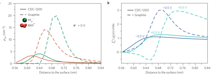
CDC-1200 Graphite PF6 BMI+ = 0 V CDC-1200 Graphite ¬0.5 V ¬0.5 V +0.5 V +0.5 V Ψ 0 5 10 15 20 25 0 1 2 3 a b ¬ ion (nm ¬3) ρ z∫ (0 q (u )/ )d u ρσ
Figure 3|Density profiles normal to the electrode surface for graphite and CDC materials.a, Ionic density profiles (ρion) for the two types of ions and
Ψ =0 V; the distances are given with respect to the surface accessible to an argon atom probe, with the origin set to the position of the carbon atoms. Further density profiles for different conditions are given in Supplementary Fig. S4. b, Integral over the distance to the surface (z) of the charge density (ρq)
of the ionic layer normalized by the electrode surface charge (σ ) for Ψ = 0.5 or −0.5 V. The function reaches a value of unity when the two quantities are equal. No overscreening effect is observed for the CDC-1200, in contrast to the graphite electrode.
(only three on average for1Ψ = 1.0 V). The minor species become more highly coordinated (five on average) inside the pore. The situation envisioned by Shim and Kim9 using ideal 1D carbon nanotube structures is recovered here as we observe, on charging, the entrance of an isolated anion in an initially empty nanotube-like pore (Fig. 2b). The volume occupied by the liquid in the electrode remains almost constant, but the ratio of numbers of ions of different charge deviates substantially from unity (Supplementary Tables S4 and S5). The charging mechanism involves the exchange of ions between the electrodes and the bulk electrolyte, and not the filling of the pores by the liquid. These results are qualitatively in accord with the model for a superionic state proposed by Kondrat and Kornyshev19,20, with the carbon surface compensating the charge of the ions. For a slit-like pore, an exponential screening of the interionic correlations by the surface is expected19. To go beyond this analysis, we now contrast the local structure inside the pores with that at a planar graphite electrode.
When studying the local structure inside the pores, special care must be taken in correctly defining the electrode surface. Following the experimental procedure, we define it as the surface accessible to an argon atom probe; the ionic density profiles are then calculated with respect to the normal to the local surface27. The first point we need to address is whether the ions adsorb on the surface of porous carbon in the same manner as on planar graphite electrodes. From Fig. 3a, which reports the density profiles in both cases, it is immediately seen that the situation is very different: in the porous electrodes, both cations and anions are allowed to approach the surface more closely—by ≈ 0.07 nm. In a parallel-plate capacitor, the capacitance varies as the inverse of the distance between the two charged planes, suggesting that this shorter carbon atom–ion distance is partly at the origin of the capacitance increase in porous CDCs.
The integration of the ionic density profiles shown in Fig. 3a gives access to the number of atoms adsorbed at the surface of the electrode. For both types of ions this number is smaller for the porous carbon than for the graphite electrodes. This result may seem rather counterintuitive given that the capacitance behaves in the opposite way, and suggests that a different charging mechanism is at play. As the liquid structure at the interface with a planar electrode is characterized by important overscreening effects, we calculate the total surface charge accumulated across the liquid-side of the interface. This quantity, normalized by the surface charge of the electrode, is reported in Fig. 3b. For an applied
¬0.02 0 0.02 0.04
Capacitance per atom (eV¬1)
Fraction of carbon atoms (%)
CDC-1200 CDC-950 Graphite 0.004 0.0110.016 0 0.5 1.0 1.5 2.0
Figure 4|Influence of the material local structure on the charging of the carbon atoms.The distributions of capacitances per atom are given for positively charged electrodes. The average value is indicated by an arrow. The distributions are much broader and more skewed in CDCs than for a planar graphite electrode. In particular, CDC-1200 seems to be an intermediate between graphite and CDC-950, owing to the presence of small graphitic domains in the sample.
potential difference of 1 V between the electrodes, the charge in the first adsorbed layer on a graphite electrode reaches a value which is three times higher than the charge of the electrode itself. This overscreening behaviour, observed for both the negative and positive graphite electrodes, arises from ionic correlations: the polarization of the first layer is coupled to that of the next layers. As a result, only a fraction of the adsorbed ions are effectively used in the electricity storage process. On the contrary, for porous electrodes, there is only one adsorbed layer, and the charging mechanism involves the exchange of ions with the bulk liquid. The total charge in this first layer balances exactly that of the electrode, resulting in a much better efficiency. Because the attraction of the ions in the first layer to the carbon surface is not balanced by that of a well-organized second layer, these ions approach the surface more closely than in the planar case. This unexpected new mechanism accounts for the larger charge stored inside microporous electrodes and reveals its microscopic origins.
Although the two carbon structures present high storage capabilities, the capacitance of CDC-950 exceeds that of CDC-1200 by 43%. These carbon materials have similar pore size distributions and average pore size (0.93 nm and 0.95 nm; ref. 21) but different local features, such as small graphitic domains in the latter (see, for example, Fig. 2a). This indicates that the local structure can affect the capacitance value. To evaluate the importance of these local effects, we compare the distribution of capacitance per carbon atom for a positively charged electrode, defined as qi/1Ψ, where qiis the local charge carried by a carbon atom, in Fig. 4. These are markedly different, with much broader and more skewed distributions for the CDCs than for graphite. For the latter, the distribution contains a relatively large amount of negative values, owing to the presence of counterions (here cations) in the first adsorbed layer5. It is centred around a peak located close to the average value, shown by an arrow on the figure. For CDCs, one observes a peak for charges close to zero (carbon atoms which are located in very small pores and are therefore not in contact with the liquid) and a large population of highly charged carbons. Positively charged cations hardly approach close to the surface, which results in a much smaller number of negatively charged carbon atoms than in planar graphite. The smaller capacitance of CDC-1200 is also reflected in the intermediate charge distribution and correlates with the greater occurrence of graphitic zones in the sample.
In conclusion, we propose a new mechanism to explain the enhanced capacitance in microporous carbon electrodes. Using a realistic model for the EDLC cell, we report capacitances in quantitative agreement with experimental results. We show that this increase is not merely due to a larger surface area and demonstrate the key role of the pore size and microstructure. The electrode is wetted by the electrolyte at null potential and the charging process involves the exchange of ions with the bulk electrolyte without changing the volume of liquid inside the electrode. This exchange is accompanied by a partial decrease of the coordination number of the ions rendered possible by the charge compensation by the electrode. The efficiency of the storage process over that of planar graphite electrodes arises from the confinement, which prevents the occurrence of overscreening effects. The computational approach presented here opens the door for systematic studies involving various pore geometries and ions of different sizes to design materials with optimized energy storage capabilities.
Methods
The MD simulations employ a coarse-grained model of the BMI-PF6ionic liquid,
in which the cations and anions are respectively represented by 3 and 1 interaction sites28. The interactions with the carbon surface are described as in our previous
study5. The CDCs produced above 1,000◦C have an electrical conductivity of
metallic nature29, so that we assume here that they are perfect conductors. Metallic
conditions inside the electrode are enforced by calculating the charge on each carbon atom such that the potential felt by this atom is constant and equal to a specified value22. This set-up was shown to provide an accurate description of the
structure of the adsorbed layer and a correct estimation of the cell capacitance in the case of graphite electrodes5.
The production runs are performed with a timestep of 2 fs in the NVT ensemble, where the temperature is maintained at 400 K by applying a Nosé–Hoover thermostat with a weak relaxation time constant of 10 ps. This temperature was chosen to have sufficiently high diffusion coefficients for the ions, so that the computational cost is minimized. Periodic boundary conditions are employed along two directions only (Fig. 1), and electrostatic interactions are calculated using a two-dimensional Ewald summation22.
The EDLC simulation cell developed for the present study is shown in Fig. 1. The microporous carbon electrodes are generated using a quenched MD procedure21; depending on the quenching rate, materials of various
pore size distributions and specific surface areas are obtained. Here we have performed simulations with two different carbons, which correspond to CDCs synthesized from crystalline TiC using respective chlorination temperatures of 1,200◦C and 950◦C (ref. 21). The pore sizes are distributed between 0.3
and 1.7 nm (ref. 21).
When passing from a bulk carbon material to the extended system of interest here, the change of periodic boundary conditions on one side of the box leads to the formation of some unphysical dangling bonds, which were removed. The system is
allowed to equilibrate first for a period of 1.25 ns, during which the carbon atoms had a charge of 0 (that is, the constant potential conditions are not set yet). Then a second equilibration of 1.2 ns is performed where the carbon atom charges are fixed at +0.01 and −0.01 e in the left and right electrodes respectively. During the last nanosecond of this equilibration period, starting configurations for the production runs are extracted every 100 ps. We then perform 10 production runs of 10 ps using the constant applied potential method described above (the choice of the applied potential value for each specific run is detailed in the Supplementary Information, together with the total number of atoms and the simulation cell geometry). For each material, two different orientations of the electrodes are tested (symmetrical or antisymmetrical), so that the total production time involved for gathering the statistics is of 200 ps.
References
1. Miller, J. R. & Simon, P. Electrochemical capacitors for energy management.
Science321, 651–652 (2008).
2. Chmiola, J. et al. Anomalous increase in carbon capacitance at pore sizes less than 1 nm. Science 313, 1760–1763 (2006).
3. Raymundo-Piñero, E., Kierzek, K., Machnikowski, J. & Béguin, F. Relationship between the nanoporous texture of activated carbons and their capacitance properties in different electrolytes. Carbon 44, 2498–2507 (2006). 4. Largeot, C. et al. Relation between the ion size and pore size for an electric
double-layer capacitor. J. Am. Chem. Soc. 130, 2730–2731 (2008). 5. Merlet, C., Salanne, M., Rotenberg, B. & Madden, P. A. Imidazolium
ionic liquid interfaces with vapor and graphite: Interfacial tension and capacitance from coarse-grained molecular simulations. J. Phys. Chem. C 115, 16613–16618 (2011).
6. Simon, P. & Gogotsi, Y. Materials for electrochemical capacitors. Nature Mater. 7, 845–854 (2008).
7. Huang, J., Sumpter, B. G. & Meunier, V. Theoretical model for nanoporous carbon supercapacitors. Angew. Chem. Int. Ed. 47, 520–524 (2008). 8. Yang, L., Fishbine, B. H., Migliori, A. & Pratt, L. R. Molecular simulation
of electric double-layer capacitors based on carbon nanotube forests. J. Am.
Chem. Soc.131, 12373–12376 (2009).
9. Shim, Y. & Kim, H. J. Nanoporous carbon supercapacitors in an ionic liquid: A computer simulation study. ACS Nano 4, 2345–2355 (2010).
10. Feng, G. A. et al. The importance of ion size and electrode curvature on electrical double layers in ionic liquids. Phys. Chem. Chem. Phys. 13, 1152–1161 (2011).
11. Kornyshev, A. A. Double-layer in ionic liquids: Paradigm change? J. Phys.
Chem. B111, 5545–5557 (2007).
12. Armand, M., Endres, F., MacFarlane, D. R., Ohno, H. & Scrosati, B. Ionic-liquid materials for the electrochemical challenges of the future. Nature Mater. 8, 621–629 (2009).
13. Lanning, O. & Madden, P. Screening at a charged surface by a molten salt.
J. Phys. Chem. B108, 11069–11072 (2004).
14. Fedorov, M. V. & Kornyshev, A. A. Ionic liquid near a charged wall: Structure and capacitance of electrical double layer. J. Phys. Chem. B 112, 11868–11872 (2008).
15. Vatamanu, J., Borodin, O. & Smith, G. D. Molecular insights into the potential and temperature dependences of the differential capacitance of a room-temperature ionic liquid at graphite electrodes. J. Am. Chem. Soc. 132, 14825–14833 (2010).
16. Fedorov, M. V. & Kornyshev, A. A. Towards understanding the structure and capacitance of electrical double layer in ionic liquids. Electrochim. Acta 53, 6835–6840 (2008).
17. Feng, G., Huang, J., Sumpter, B. G., Meunier, V. & Qiao, R. A ‘counter-charge layer in generalized solvents’ framework for electrical double layers in neat and hybrid ionic liquid electrolytes. Phys. Chem. Chem. Phys. 13, 14723–14734 (2011).
18. Bazant, M. Z., Storey, B. D. & Kornyshev, A. A. Double layer in ionic liquids: Overscreening versus crowding. Phys. Rev. Lett. 106, 046102 (2011). 19. Kondrat, S. & Kornyshev, A. A. Superionic state in double-layer capacitors
with nanoporous electrodes. J. Phys. Condens. Matter 23, 022201 (2011). 20. Kondrat, S., Georgi, N., Fedorov, M. V. & Kornyshev, A. A. A superionic state
in nanoporous double-layer capacitors: Insights from Monte Carlo simulations.
Phys. Chem. Chem. Phys.13, 11359–11366 (2011).
21. Palmer, J. C. et al. Modeling the structural evolution of carbide-derived carbons using quenched molecular dynamics. Carbon 48, 1116–1123 (2010). 22. Reed, S. K., Lanning, O. J. & Madden, P. A. Electrochemical interface
between an ionic liquid and a model metallic electrode. J. Chem. Phys. 126, 084704 (2007).
23. Pounds, M., Tazi, S., Salanne, M. & Madden, P. A. Ion adsorption at a metallic electrode: An ab initio based simulation study. J. Phys. Condens. Matter 21, 424109 (2009).
24. Chmiola, J., Largeot, C., Taberna, P-L., Simon, P. & Gogotsi, Y. Desolvation of ions in subnanometer pores and its effect on capacitance and double-layer theory. Angew. Chem. Int. Ed. 47, 3392–3395 (2008).
25. Hardacre, C., Holbrey, J. D., Nieuwenhuyzen, M. & Youngs, T. G. A. Structure and solvation in ionic liquids. Acc. Chem. Res. 40, 1146–1155 (2007). 26. Ohkubo, T. et al. Restricted hydration structures of Rb and Br ions confined in
slit-shaped carbon nanospace. J. Am. Chem. Soc. 124, 11860–11861 (2002). 27. Willard, A. P. & Chandler, D. Instantaneous liquid interfaces. J. Phys. Chem. B
114, 1954–1958 (2010).
28. Roy, D. & Maroncelli, M. An improved four-site ionic liquid model. J. Phys.
Chem. B114, 12629–12631 (2010).
29. Vora, P. M. et al. Correlating magnetotransport and diamagnetism of sp2–bonded carbon networks through the metal–insulator transition. Phys. Rev. B84, 155114 (2011).
Acknowledgements
We acknowledge the support of the French Agence Nationale de la Recherche (ANR) under Grant ANR-2010-BLAN-0933-02 (‘Modelling the Ion Adsorption in Carbon
Micropores’). We are grateful for the computing resources on Hector (UK National HPC) provided by EPSRC through the UKCP consortium. Y.G. is supported by the US National Science Foundation under International Collaborations in Chemistry Grant No. 0924570. P.S. and Y.G. thank the Partner University Fund (PUF) for funding their collaborative efforts. We thank J. C. Palmer and K. Gubbins for providing us the raw data from ref. 21.
Author contributions
C.M., B.R., P.A.M. and M.S. designed the research. C.M. carried out simulations. All authors contributed to the analysis and discussion of the data and writing the manuscript.
Additional information
The authors declare no competing financial interests. Supplementary information accompanies this paper on www.nature.com/naturematerials.Reprints and permissions information is available online at www.nature.com/reprints. Correspondence and requests for materials should be addressed to M.S.