HAL Id: hal-01593122
https://hal.archives-ouvertes.fr/hal-01593122
Submitted on 26 Sep 2017
HAL is a multi-disciplinary open access
archive for the deposit and dissemination of
sci-entific research documents, whether they are
pub-lished or not. The documents may come from
teaching and research institutions in France or
abroad, or from public or private research centers.
L’archive ouverte pluridisciplinaire HAL, est
destinée au dépôt et à la diffusion de documents
scientifiques de niveau recherche, publiés ou non,
émanant des établissements d’enseignement et de
recherche français ou étrangers, des laboratoires
publics ou privés.
Cooperative Resource Management and Power
Allocation for Multiuser OFDMA Networks
Mohamad Yassin, Samer Lahoud, Marc Ibrahim, Kinda Khawam, Dany
Mezher, Bernard Cousin
To cite this version:
Mohamad Yassin, Samer Lahoud, Marc Ibrahim, Kinda Khawam, Dany Mezher, et al.. Cooperative
Resource Management and Power Allocation for Multiuser OFDMA Networks. IET Communications,
Institution of Engineering and Technology, 2017, 11 (16), pp.2552 - 2559. �10.1049/iet-com.2017.0201�.
�hal-01593122�
Cooperative Resource Management and Power
Allocation for Multiuser OFDMA Networks
Mohamad Yassin
∗‡?, Samer Lahoud
∗, Marc Ibrahim
‡, Kinda Khawam
§, Dany Mezher
‡, Bernard Cousin
∗∗University of Rennes 1, IRISA, Campus de Beaulieu, 35042 Rennes, France
‡Saint-Joseph University, ESIB, Campus des Sciences et Technologies, Mar Roukoz, Lebanon §University of Versailles, PRISM, 45 Avenue des Etats-Unis, 78035 Versailles, France
?Corresponding author’s email: [email protected]
Abstract—Mobile network operators are facing the challenge to increase network capacity and satisfy the growth in data traffic demands. In this context, Long Term Evolution (LTE) networks, LTE-Advanced networks, and future mobile networks of the Fifth Generation seek to maximize spectrum profitability by choosing the frequency reuse-1 model. Due to this frequency usage model, advanced radio resource management and power allocation schemes are required to avoid the negative impact of interference on system performance. Some of these schemes modify resource allocation between network cells, while others adjust both resource and power allocation. In this article, we introduce a cooperative distributed interference management algorithm, where resource and power allocation decisions are jointly made by each cell in collaboration with its neighbor-ing cells. Objectives sought are: increasneighbor-ing user satisfaction, improving system throughput, and increasing energy efficiency. The proposed technique is compared to the frequency reuse-1 model and to other state-of-the-art techniques under uniform and non-uniform user distributions and for different network loads. We address scenarios where throughput demands are homoge-neous and non-homogehomoge-neous between network cells. System-level simulation results demonstrate that our technique succeeds in achieving the desired objectives under various user distributions and throughput demands.
Index terms— Inter-Cell Interference Coordination, RRM, 3GPP LTE, satisfaction function, fractional frequency reuse.
I. INTRODUCTION
The increasingly growing demand for mobile broadband communications and the proliferation of mobile applications and services have led to the dense deployment of mobile networks with aggressive frequency reuse patterns. In fact, the Long Term Evolution (LTE) [1] of Universal Mobile Terrestrial radio access System (UMTS) allows using all the available spectrum according to the frequency reuse-1 model. While trying to improve system throughput and increase spec-trum profitability, mobile network operators find themselves constrained by Inter-Cell Interference (ICI) problems. ICI re-duces Signal-to-Interference and Noise Ratio (SINR), and has a negative impact on system performance. Another important concern for mobile network operators is minimizing signaling traffic required to coordinate resource and power allocation be-tween LTE/LTE-A base stations, also called evolved-NodeBs (eNodeBs).
Third Generation Partnership Project (3GPP) has chosen Orthogonal Frequency Division multiple Access (OFDMA) technique for the downlink of the radio interface [2]. The
smallest resource unit to be allocated to a User Equipment (UE) is called Resource Block (RB). At each eNodeB, the scheduler allocates the available RBs for active UEs every Transmit Time Interval (TTI), also called scheduling period (1 ms). There is no intra-cell interference problems, since each RB is allocated to only one UE within the same cell [3].
Several Inter-Cell Interference Coordination (ICIC) tech-niques are conceived to mitigate the negative impact of ICI on system performance. We classify them into static and dynamic techniques. For instance, Fractional Frequency Reuse (FFR) and Soft Frequency Reuse (SFR) [4] apply pre-planned frequency and power allocation strategies between eNodeBs of the same cluster. Dynamic ICIC techniques are capable of responding to time-varying traffic demands in the network by modifying RB attribution, power allocation or both on a smaller time scale.
In this article, we introduce a cooperative ICIC technique that exploits communications between adjacent eNodeBs to reduce ICI problems in multiuser OFDMA networks such as LTE/LTE-A networks. Our technique aims at improving system throughput, UE satisfaction, and energy efficiency under various UE distributions and network loads. We de-fine a satisfaction function as well as satisfaction throughput thresholds for each cell in the simulated network. The time scale of the proposed technique is higher than the scheduling period, since it sets RB and power allocation restrictions for the scheduler of each eNodeB. It also adjusts RB distribution between cell-center and cell-edge zones for each LTE cell. Our technique is compared to the frequency reuse-1 model, FFR, SFR, and other ICIC techniques. System-level simulation results show that the proposed technique achieves significant improvements under various UE distributions and network loads.
The rest of the article is organized as follows: in sec-tion II, we describe existing ICIC techniques. System model is reported in section III, while details about our proposed ICIC algorithm are given in section IV. System-level simulator and simulation parameters are described in section V, and simulation results are reported in section VI. Conclusion is given in section VII.
II. ICIC APPROACHES
The frequency reuse-N model [5] mitigates inter-cell in-terference. However, the spectral efficiency is reduced, since only N1 of the available spectrum is used in each cell. The frequency reuse-1 model [6] increases spectral efficiency and network capacity due to dense usage of the available RBs in the network. However, ICI problems have a negative impact on UE throughput, especially for UEs located at the edge of the cell.
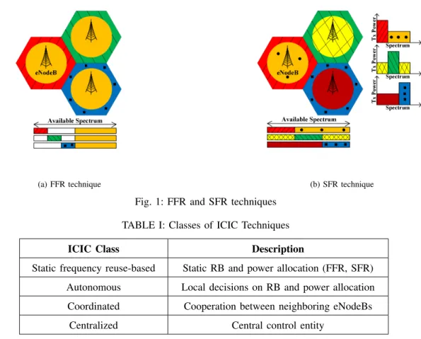
FFR is a static ICIC technique where restrictions on RB usage [7] are made to protect cell-edge UEs. FFR assumes that UEs of the cell-center zone do not receive high power interfering signals from the neighboring cells. Nevertheless, UEs in cell-edge zone are close to the cell boundary and receive strong ICI. After creating two zones per cell, FFR divides the available spectrum into a few non-overlapping frequency sub-bands [8]. Cell-center and cell-edge UEs from the same cell operate over different frequency sub-bands. Cell-edge UEs of the neighboring cells also operate over non-overlapping frequency sub-bands as shown in Fig. 1a
SFR [9] protects cell-edge UEs by reducing the transmission power allocated to their interfering RBs in the cell-center zones of the neighboring cells. SFR’s resource and power allocation for a cluster of three adjacent LTE cells is illustrated in Fig. 1b. SFR succeeds in mitigating ICI without largely sacrificing spectral efficiency [10]. Restrictions on RB and power allocation for both FFR and SFR techniques are stati-cally made in each cell, and no modifications are made even when network load increases, or when UEs are not uniformly distributed between cell zones.
Several dynamic ICIC techniques are introduced [11–13]; some of them adjust frequency and power allocation in each cell locally, without any cooperation between eNodeBs. Other techniques depend on the signaling exchange between neigh-boring eNodeBs. An example of autonomous ICIC techniques is the heuristic power control algorithm introduced in [14]. The scheduler of each eNodeB locally adjusts downlink trans-mission power allocated to each RB depending on the received Channel Quality Indication (CQI) feedbacks. Authors in [15] describe an ICIC technique that responds to network dynamics, through exchange of interference related information among neighboring cells. It is a dynamic cooperative FFR-based ICIC technique. Other ICIC techniques require the existence of a management entity to control RB and power allocation over the entire network. They are known as centralized techniques, and they are characterized by a heavy signaling burden and high complexity. For instance, in [16], a centralized entity collects information about RB usage and ICI from a set of eNodeBs, then it sends its decisions to the network schedulers. Moreover, Coordinated Multi-Point (CoMP) [17, 18] creates a framework of transmission and reception methods using multi-ple geographically distributed antennas. Real-time information about RB allocation and interference status are exchanged among eNodeBs through X2 interface. The classification of ICIC techniques is summarized in Table I.
III. SYSTEMMODEL
ICIC techniques proposed for multi-user OFDMA [19] networks, divide each cell into cell-center and cell-edge zones. The former contains UEs close the serving eNodeB, while the latter contains UEs located near the cell boundary. This geographical classification assumes that cell-center UEs are characterized by high SINR values, and that cell-edge UEs have lower SINR. However, we have cell-center UEs suffering from interference or fading problems, as well as cell-edge UEs with good radio conditions due to shadow fading. This approach also requires the knowledge of the exact position of each UE existing in the network, which results in an additional information exchange and processing load. In our work, we classify UEs according to their radio conditions. Instead of using geographical positions, we perform UE classification according to mean wideband SINR, since it reflects the useful signal power to the received interference. An SINR threshold (SIN Rthreshold) is set to classify UEs: when mean SINR of a UE is higher than the predefined SIN Rthreshold, it is considered as a Good Radio (GR) conditions UE; otherwise, it is considered as a Bad Radio (BR) conditions UE. GR UEs are commonly known as cell-center UEs, and BR UEs as cell-edge UEs. Our classification is more accurate than the traditional approach: UEs suffering from ICI are classified as BR UEs, even if they are close to the serving eNodeB. Moreover, it does not require any localization information.
Let K denote the set of active UEs, I denotes the set of LTE/LTE-A eNodeBs, and N is the set of RBs available in each cell. We consider a UE k attached to cell i and allocated RB n. The corresponding SINR is given by:
SIN Rik, n= P i n· Gik, n P j6=i Pnj· Gjk, n+ PT N , (1) where Pi
n is the downlink transmission power allocated by cell i for the RB n, Gi
k, n is channel gain for UE k served by eNodeB i on RB n, and PT N is the thermal noise power on the considered RB. Channel gain includes all key fading components i.e., path loss, shadowing and multipath that UE k experiences on RB n. Indexes i and j refer to the serving and the interfering cells, respectively.
Let Rik, n denote the achievable rate on RB n for user k in the cell i, then:
Rik, n= f (SINR i
k, n). (2) Where f (.) is the adaptive modulation and coding function that maps SINR to rate. In our work, we consider an LTE/LTE-A network of several adjacent hexagonal cells. Each cell is equipped with 120◦ directional transmit antennas with an azimuth offset of 30◦. The frequency reuse-1 model is used to serve UEs existing within each cell.
LTE/LTE-A networks require the transmission of UE feed-back in order to adapt transmission to current channel condi-tions. In this context, CQI is a four-bit value sent from UE to eNodeB [20] that reflects the level of SINR of a given
(a) FFR technique (b) SFR technique
Fig. 1: FFR and SFR techniques TABLE I: Classes of ICIC Techniques ICIC Class Description
Static frequency reuse-based Static RB and power allocation (FFR, SFR) Autonomous Local decisions on RB and power allocation Coordinated Cooperation between neighboring eNodeBs
Centralized Central control entity
frequency band in downlink channels. It indicates the highest modulation and coding scheme that guarantees a block error rate lower than 10% for physical downlink shared channel transmissions. Several reporting modes are supported: for example, wideband CQI feedbacks reflect the average channel quality across the entire cell bandwidth, while specific reports require the transmission of one CQI per configured sub-band (narrowband CQI feedbacks).
We consider elastic traffic sessions, such as file transfer, web traffic, and email, since these are the traditional data services in mobile networks [21]. Then we define the satisfaction function for each UE k at time t, Sk(t), as a function of the achievable throughput for this UE, Rk(t), and it is given by [21]:
Sk(t) = 1 − exp(− Rk(t)
RS
), (3)
where RS is the satisfaction throughput for the considered UE, or the mean throughput beyond which UE satisfaction exceeds 0.63. Satisfaction with respect to Rk has a concave shape; it increases slowly as the throughput exceeds the sat-isfaction throughput RS for UE k. Therefore, the satisfaction of an LTE/LTE-A cell i having Ki UEs is given by:
Si(t) = Ki P k=1 Sk(t) Ki . (4)
LTE/LTE-A cells are hexagonal, and each cell exchanges signaling messages with its six neighboring cells. The cell i calculates mean satisfaction function S for the considered cluster C that contains KC UEs:
S = KC P k=1 Sk(t) KC . (5)
IV. COOPERATIVEICIC TECHNIQUE
We introduce a cooperative ICIC technique for multiuser OFDMA networks, where adjacent eNodeBs collaborate in order to reduce ICI problems. It is a distributed technique that requires cooperation between adjacent eNodeBs to adjust RB and power allocation. Initially, RB and power distribution between the different cells is performed according to the SFR scheme. Thus, the frequency reuse-1 model is chosen to maximize spectral efficiency. Decentralized cooperative interference mitigation schemes are adequate for medium-sized and big-medium-sized networks, where the centralized schemes face severe limitations in terms of signaling and processing load.
Our technique makes use of the signaling messages ex-changed between neighboring eNodeBs over X2 interface. Each cell has local information, concerning SINR of its active UEs, as well as their achievable throughputs and their
satisfac-tion. It also requests information about UE satisfaction from the neighboring cells. Therefore, adjacent eNodeBs adjust power allocation to the different RBs, in order to reduce ICI and to improve UE satisfaction in a collaborative manner.
As explained in previous sections, an LTE/LTE-A cell is divided into two zones, according to UEs wideband SINR values: GR and BR zones. Initially, one third of the available spectrum in each cell is kept for BR UEs, and the maximum downlink transmission power (Pmax) is allocated to each RB used in this zone. The remaining bandwidth is used at a lower transmission power (PGR) in the GR zone. BR UEs of adja-cent cells operate on different frequency sub-bands, and they receive low power interfering signals from their neighboring cells. ICIC algorithm intervention period is chosen to be higher than scheduling period (1 ms) and CQI feedback reception delay, so the scheduler of each eNodeB has enough time to investigate the impact of RB and power allocation changes on UEs throughput. Each cell performs periodically, every T TTIs, where T ≥ max(1 TTI, CQI feedback delay), the following actions:
1) Classify the available RBs according to mean narrow-band CQI feedback values
2) Collect information about mean throughput per UE in the neighboring cells
3) Request information about RB and power distribution from all the neighboring cells
4) Send Stop messages to the neighboring cells 5) Calculate the local cell satisfaction Si(t)
6) Calculate mean satisfaction for the neighboring cells S(t)
7) When unsatisfied, increase the downlink transmission power allocated to the worst low power RB, and ask the neighboring cells transmitting at high power to reduce their downlink transmission power allocated to this RB 8) When satisfied, keep the same RB and power distribution 9) Send Release messages to the neighboring cells 10) Locally adjust RB allocation between GR and BR zones
of the current cell according to throughput demands in each zone
Our proposed technique exploits the fact that adjacent eN-odeBs can exchange information related to UE throughput in each cell. When a given cell decides to perform the cooperative ICIC procedure, it sends Stop messages to its neighboring cells to avoid any potential conflict that might occur when adjacent cells take simultaneous power allocation decisions. Since the X2 interface between adjacent eNodeBs is bidirectional, the Stop messages contain a time stamp, that allows to avoid any potential deadlock that might occur if two eNodeBs send simultaneous Stop messages to each other. Every eNodeB calculates the mean satisfaction for its active UEs, as well as mean satisfaction for UEs in the neighboring cells. We tolerate a slight difference (∆iS) between the satisfaction of the local cell and mean satisfaction per cell to reduce the number of interventions performed by each cell. When power adjustments are done, a Release message is sent to the neighboring cells,
and RB distribution between GR and BR zones is locally made according to throughput demands in each zone.
The distributed algorithm operates at the scheduler of each eNodeB as shown in Algorithm 1. Ri(t) denotes the mean throughput per UE in cell i; I is the number of cells in the neighboring cells pool I. Pi
n is the downlink transmission power allocated by cell i to the RB n. Pmax is the power allocated to a BR RB, while PGR is the downlink power per GR RB. RGR and RBR denote the mean throughput per GR and BR zones, respectively. After receiving narrowband CQI feedbacks from the UEs, eNodeB calculates mean CQI per RB. The coefficient γ equals 0.5, and it is used to emphasize the last received CQI feedback value, CQIn(t). eNodeB classifies the available RBs according to mean CQI values, then it sends signaling messages to its neighbors so that downlink transmission power allocated to the different RBs is kept the same.
Our algorithm consists of two phases: in the first phase, ad-jacent eNodeBs exchange the necessary information required to coordinate power allocation among neighboring cells, while in the second phase, each cell locally modifies RB distribution between the different zones. After setting restrictions on power allocation with its neighbors, each cell adjusts RB allocation between GR and BR zones according to UE throughput demands in each zone. The objective behind second phase is to dynamically respond to throughput demands within each cell, even when UE distributions are not homogeneous among GR and BR zones.
Figure 2 shows a cluster of seven adjacent hexagonal LTE/LTE-A cells. We assume that the central cell (eNodeB 7) has the highest traffic load, and seeks to improve its mean UE satisfaction. After exchanging the necessary signaling messages with its neighboring cells, eNodeB 7 increases the downlink transmission power allocated to a portion of the available bandwidth that was originally used at a low trans-mission power. It also orders the concerned neighboring cells (eNodeBs 1, 3, and 5) to reduce their downlink transmission power allocated to this portion of the spectrum. Therefore, eNodeB 7 reduces ICI and improves mean UE satisfaction via collaborative power allocation decisions. Moreover, it autonomously adjusts resource allocation between cell-center and cell-edge zones based on throughput demands in each zone.
V. SIMULATIONPARAMETERS
An LTE downlink system level simulator [22] is chosen as simulation platform. The original version of the simulator in-cludes the frequency reuse-1 model as well as FFR technique. In order to compare our technique with the frequency reuse-1 model and other reference ICIC techniques, we integrated SFR scheme within the simulator. We also adjusted the power allocation scheme so that the power mask can be modified according to the used technique. Finally, we integrated our proposed cooperative distributed ICIC algorithm. The simu-lated network includes seven adjacent hexagonal LTE/LTE-A cells, with a 5 MHz operating bandwidth. Since the total
Algorithm 1 Cooperative ICIC
1: Initially, RBs are distributed according to SFR
2: All UEs send CQI feedbacks to the eNodeB
3: for each RB ∈ RB pool do 4: CQIin(t) = K P k=1 CQIk n(t) K
5: CQIin(t) = γ × CQIin(t-1) + (1 − γ) × CQIn(t)
6: end for 7: Every T TTIs:
8: Cell i sends Stop messages to its neighbors
9: Sk(t) = 1 − exp(−Rk(t) RS ) 10: Si(t) = Ki P k=1 Sk(t) Ki 11: S(t) = KC P k=1 Sk(t) KC 12: if (Si(t) < (1 − ∆i S) × S(t)) then
13: Select the low power RB n with the lowest CQIin(t)
14: Pni ← Pmax
15: Pnj ← PGR; ∀j ∈ I
16: else
17: Keep the same power allocation mask
18: end if
19: Send Release messages to the neighboring cells
20: if (RGR − RBR > ∆th) then
21: Select RB n with the highest CQIi
n(t) from GR zone
22: Allocate this RB to the BR zone
23: else if (RBR − RGR > ∆th) then
24: Select RB n with the lowest CQIi
n(t) from BR zone
25: Allocate this RB to the GR zone
26: else
27: Keep the same RB distribution
28: end if
Fig. 2: LTE network of seven adjacent cells
bandwidth per RB equals 180 kHz, we have 25 RBs available in each cell. Traffic model is full buffer; thus, the available spectrum is permanently used to serve active UEs. With the
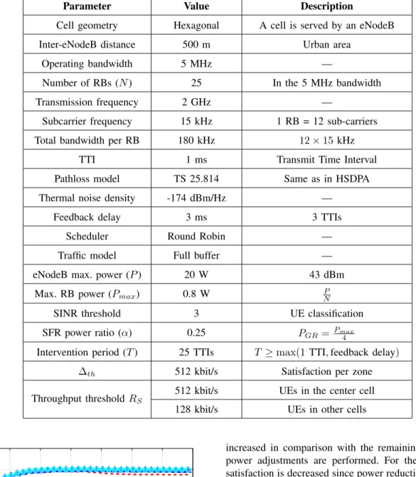
full buffer model, the maximum ICI is generated since all the available spectrum is simultaneously used in the adjacent cells. Thus, we place ourselves in a worse-case scenario. Simulation parameters are given in Table II.
VI. SIMULATIONRESULTS
A. Tolerated Satisfaction Ratio B. Tolerated Satisfaction Ratio
We simulate an LTE/LTE-A network having seven adjacent hexagonal cells, where each cell is serving 10 UEs. Simulation time is 350 TTIs (350 ms). Throughput satisfaction threshold for the center cell equals 4×RS; where RS is satisfaction threshold for UEs in all the other cells. In other words, throughput demands are not the same through the simulated network: it is required to provide higher throughputs for central cell UEs, since their satisfaction throughput threshold exceeds that of the other UEs.
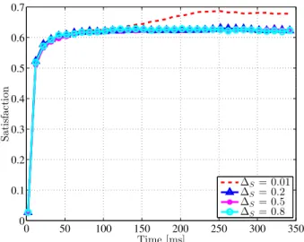
First, we study the impact of the tolerated satisfaction ratio ∆S, which is a percentage of the mean satisfaction value, on the central cell satisfaction and mean satisfaction for the entire network. Simulations are repeated 100 times, and satisfaction versus time for central cell UEs and for all UEs versus time are reported in Fig. 3 and Fig. 4 respectively. The objective of this study is to find the most adequate value of ∆S i.e., the value that maximizes system satisfaction.
0 50 100 150 200 250 300 350 0 0.1 0.2 0.3 0.4 0.5 0.6 0.7 Time [ms] S at is fac ti on ∆S= 0.01 ∆S= 0.2 ∆S= 0.5 ∆S= 0.8
Fig. 3: Central cell satisfaction versus time
For tolerated satisfaction ratios higher than 20%, power allocation over the different RBs is kept the same, since all the cells achieve an acceptable satisfaction compared to mean satisfaction per UE. However, when ∆S equals 1%, satisfaction for central cell UEs is increased, while mean satisfaction per UE is slightly decreased with time. When the tolerated satisfaction is lower than 0.01×S, the central cell decides to increase transmission power allocated to some RBs (that were already used with a lower transmission power), and it orders all its neighbors to reduce the downlink power allocated to these RBs. Satisfaction for central cell UEs is
TABLE II: Simulation Parameters
Parameter Value Description
Cell geometry Hexagonal A cell is served by an eNodeB Inter-eNodeB distance 500 m Urban area
Operating bandwidth 5 MHz —
Number of RBs (N ) 25 In the 5 MHz bandwidth Transmission frequency 2 GHz —
Subcarrier frequency 15 kHz 1 RB = 12 sub-carriers Total bandwidth per RB 180 kHz 12 × 15 kHz
TTI 1 ms Transmit Time Interval Pathloss model TS 25.814 Same as in HSDPA Thermal noise density -174 dBm/Hz —
Feedback delay 3 ms 3 TTIs Scheduler Round Robin — Traffic model Full buffer — eNodeB max. power (P ) 20 W 43 dBm
Max. RB power (Pmax) 0.8 W NP SINR threshold 3 UE classification SFR power ratio (α) 0.25 PGR= Pmax
4
Intervention period (T ) 25 TTIs T ≥ max(1 TTI, feedback delay) ∆th 512 kbit/s Satisfaction per zone
Throughput threshold RS 512 kbit/s UEs in the center cell 128 kbit/s UEs in other cells
0 50 100 150 200 250 300 350 0 0.1 0.2 0.3 0.4 0.5 0.6 0.7 0.8 Time [ms] S at is fac ti on ∆S= 0.01 ∆S= 0.2 ∆S= 0.5 ∆S= 0.8
Fig. 4: Mean satisfaction versus time
increased in comparison with the remaining cases where no power adjustments are performed. For the remaining cells, satisfaction is decreased since power reduction will reduce the achievable throughput. Thus, mean satisfaction per UE in the entire network is slightly reduced. When ∆S is set to 1%, we maximize the satisfaction of the whole system.
In the following, the tolerated satisfaction ratio ∆S equals 1%. Hence, when the mean satisfaction per UE exceeds by 1% the satisfaction of a cell, it decides to launch a cooperative ICIC procedure with its neighbors in order to adjust power allocation and improve the satisfaction of its UEs. We compare our proposed cooperative ICIC technique with the frequency reuse-1 model, FFR, SFR, an adaptive ICIC technique given in [12], and an autonomous ICIC technique introduced in [23], where power allocation for the different RBs is not modified among adjacent eNodeBs. Nevertheless, periodic interventions are made by the scheduler of each eNodeB, locally, in order to find out whether GR or BR users are unsatisfied. RB distribution between cell zones is adjusted according to UEs
throughput demands in each zone.
The adaptive ICIC technique [12] operates as follows: • UEs are divided into cell-edge and cell-center UE groups. • RB and power allocation to the cell-edge group is per-formed. After that, the RB and power allocation to the cell-center group is performed.
• The RBs and power allocation to cell-edge UEs is performed using a waterfilling-based power allocation algorithm, so that all the cell-edge UEs satisfy the pre-determined target throughput.
• Problem constraints are related to the minimum through-put per UE, and to the maximum downlink transmission power.
• Each cell solves its own optimization problem with minimal exchange of information between the cells. C. Throughput Cumulative Distribution Function (CDF)
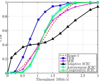
Under the same simulation conditions, we study the impact of each technique on throughput CDF for all UEs existing in the network. Throughput CDF is shown in Fig. 5.
0 0.5 1 1.5 2 2.5 3 0 0.2 0.4 0.6 0.8 1 Throughput [Mbit/s] C D F Reuse-1 FFR SFR Adaptive ICIC Autonomous ICIC Cooperative ICIC
Fig. 5: Throughput cumulative distribution function Although FFR succeeds in reducing ICI, especially for BR UEs, restrictions on RB usage between the different zones of each cell will reduce the amount of available spectrum dedicated for the existing UEs. Thus, FFR shows a lower percentage of UEs having throughputs higher than 512 kbit/s in comparison with reuse-1, SFR, autonomous, and coop-erative ICIC techniques. In fact, throughput CDF for FFR reaches the maximum value of dissatisfaction before that of reuse-1, SFR, autonomous, and cooperative ICIC techniques. SFR improves the frequency reuse-1 model by reducing the percentage of UEs with throughputs lower than 1 Mbit/s. Our cooperative ICIC technique shows the highest percentage of UEs having high throughputs, and it reaches its maximum value of dissatisfaction for the same throughput as for reuse-1. We also notice that the adaptive ICIC technique does not succeed in reducing the percentage of UEs characterized by low throughput values, since its CDF curve shows the
highest values for throughputs less than 0.5 Mbit/s. In fact, this technique does not take ICI problems into account, and resource allocation is performed in a manner that improves spectral efficiency. Therefore, BR UEs throughput decreases and more RBs are allocated to GR UEs in order to maximize system throughput.
D. Satisfaction Cumulative Distribution Function
For the same simulated scenario, we show satisfaction cu-mulative distribution function for all the compared techniques. Satisfaction function ranges from 0 (minimum satisfaction) to 1 (maximum satisfaction). Satisfaction CDF for the per-formed simulations are shown in Fig. 6.
0 0.2 0.4 0.6 0.8 1 0 0.2 0.4 0.6 0.8 1 Satisfaction S at is fac ti on C D F Reuse-1 FFR SFR Adaptive ICIC Autonomous ICIC Cooperative ICIC
Fig. 6: Satisfaction cumulative distribution function According to these results, adaptive ICIC always shows the highest percentage of UEs with low satisfaction values. The frequency reuse-1 model, SFR, and autonomous ICIC techniques have approximately the same satisfaction CDF, and our proposed cooperative ICIC technique has the best satisfaction CDF in comparison with the other techniques. For instance, when cooperative ICIC is applied, only 10% of UEs have a satisfaction below 0.9, while 30% of the active UEs have their satisfaction below 0.9 for the adaptive ICIC technique. Therefore, our technique improves UE satisfaction by adjusting power allocation over RBs used simultaneously in adjacent LTE cells.
E. Unsatisfied UEs versus Network Load
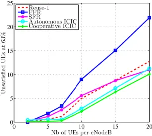
For an LTE network of seven adjacent LTE cells, with 25 RBs available in each cell, we study the impact of network load (number of UEs per eNodeB) on the percentage of unsatisfied UEs in the network. The percentage of satisfied UEs at 63% denotes the percentage of UEs characterized by a mean throughput higher than the satisfaction throughput threshold RS. When a UE has its throughput equal to RS, the satisfaction function equals 0.63. We investigate the percentage of UEs that are unsatisfied at 63% i.e., the number of UEs characterized by a throughput lower than RS, among all the
active UEs in the network. Figure 7 shows the percentage of unsatisfied UEs at 63% versus the number of UEs per eNodeB.
0 5 10 15 20 0 5 10 15 20 25
Nb of UEs per eNodeB
Un sat is fi ed UE s at 63% Reuse-1 FFR SFR Autonomous ICIC Cooperative ICIC
Fig. 7: Unsatisfied UEs at 63% versus network load For very low network load scenarios, such as two or five UEs per eNodeB, the frequency reuse-1 model and all the other ICIC techniques have approximately the same percentage of unsatisfied UEs. However, when the number of UEs per eNodeB increases, throughput demands become more difficult to satisfy, especially with the increased ICI. FFR has always the highest percentage of unsatisfied UEs, which increases with network load. Unsatisfied UEs with SFR technique are comparable to those with the frequency reuse-1 model. More-over, their percentage decreases when network load increases. Our proposed cooperative ICIC technique shows the lowest percentage of unsatisfied UEs regardless of the number of UEs per eNodeB. It adjusts power allocation over the available RBs for each cell in a collaborative manner, which reduces the number of UEs with low satisfaction values.
F. Energy Efficiency versus UE Distribution
We also investigate the impact of UE distribution on the performance of the compared ICIC techniques. We generate scenarios with different UE distributions by controlling the percentage of GR UEs among all the existing UEs in each cell. For every UE distribution scenario, simulations are repeated 50 times, and mean energy efficiency values are shown in Fig. 8. According to these results, the frequency reuse-1 model shows always the lowest energy efficiency among all the compared techniques. In fact, when the maximum downlink transmission power is permanently allocated to all the avail-able RBs, power consumption increases, ICI increases and the achievable throughput is reduced, especially for BR UEs. When using FFR, a fraction of the available spectrum is not used in each cell; therefore, no downlink transmission power is allocated to the unused frequency sub-band. Power consumption is reduced, while also improving SINR for BR UEs. For these reasons, FFR improves energy efficiency when compared to the frequency reuse-1 model. We also notice that
20 30 40 50 60 70 80 0.4 0.6 0.8 1 1.2 1.4 1.6 1.8 2 % of GR users E n er gy effi ci en cy [M b it /s /W ] Reuse−1 FFR SFR Adaptive ICIC Autonomous ICIC Cooperative ICIC
Fig. 8: Energy efficiency versus UE distribution
the adaptive ICIC technique is a compromise between the frequency reuse-1 model and FFR technique in terms of energy efficiency, since it succeeds in improving system performance in comparison with the frequency reuse-1 model.
Our cooperative ICIC technique shows an energy efficiency comparable to that of SFR. When there is more BR UEs in the network (the percentage of GR UEs is low), ICIC algorithm increases downlink transmission power allocated to selected RBs to increase BR UEs satisfaction. Thus, total power consumption increases, and energy efficiency is slightly lower than that of SFR. However, it shows the highest energy efficiency when the majority of UEs are GR UEs.
VII. CONCLUSION
Dense frequency reuse model is used in multiuser OFDMA networks, such as LTE/LTE-A networks to increase spectral efficiency, and to improve network capacity. However, the re-sulting ICI problems have a negative impact on UE throughput and system performance. ICIC techniques are proposed to improve UE throughput, without largely sacrificing spectral efficiency. They include static techniques, such as FFR and SFR, autonomous techniques, cooperative techniques, and cen-tralized techniques. Cencen-tralized resource and power allocation techniques are adequate for small-sized networks, since they generate a large amount of signaling overhead. Autonomous resource allocation schemes do not generate an additional signaling overhead. Thus, they are adequate for large-sized networks. The cooperative ICIC techniques are therefore a compromise between centralized and autonomous approaches. In this article, we introduced a cooperative distributed ICIC technique where communications between adjacent eNodeBs are required to adjust RB and power allocation. Our algo-rithm consists of two phases: in the first phase, signaling messages are exchanged to get the necessary information about UE satisfaction and power allocation in the neighboring cells. Decisions concerning transmission power adjustments are made in a collaborative manner during this phase. In the
second phase, the scheduler of each eNodeB locally adjusts restrictions on RB distribution between cell zones according to UE demands per zone. Simulation results show that our technique improves energy efficiency, enhances throughput cumulative distribution function, and reduces the percentage of unsatisfied UEs, when compared to the frequency reuse-1 model, FFR, SFR, adaptive ICIC, and non-cooperative ICIC techniques.
REFERENCES
[1] 3GPP, “Physical Layer Aspects for Evolved Universal Terrestrial Radio Access (UTRA) (Release 7),” 3GPP TR 25.814 V7.1.0, Tech. Rep., 2006.
[2] H. Schulze and C. Lueders, Theory and Applications of OFDM and CDMA Wideband Wireless Communications, 1st ed., Wiley, Ed. Chich-ester: UK: Wiley, 2005, vol. 1.
[3] Y. Sun, R. P. Jover, and X. Wang, “Uplink Interference Mitigation for OFDMA Femtocell Networks,” IEEE Trans. Wireless Commun., vol. 11, no. 2, pp. 614–625, February 2012.
[4] R. Kwan and C. Leung, “A survey of scheduling and interference mitigation in lte,” J. Electrical and Computer Engineering, vol. 2010, 2010.
[5] V. Donald, “Advanced mobile phone service: The cellular concept,” Bell System Technical Journal, The, vol. 58, no. 1, pp. 15–41, Jan 1979. [6] M. AboulHassan, E. Sourour, and S. Shaaban, “Novel Cell Selection
Algorithm for Improving Average User’s Effective Data Rate in LTE HetNets,” in 2014 IEEE Symposium on Computers and Communication, June 2014, pp. 1–6.
[7] N. Hassan and M. Assaad, “Optimal Fractional Frequency Reuse (FFR) and Resource Allocation in Multiuser OFDMA System,” in International Conference on Information and Communication Technologies ICICT ’09., Karachi, August 2009, pp. 88–92.
[8] K. Yang, “Interference Management in LTE Wireless Networks,” IEEE Wireless Commun., vol. 19, no. 3, pp. 8–9, July 2012.
[9] C. Jiming, W. Peng, and Z. Jie, “Adaptive Soft Frequency Reuse Scheme for in-Building Dense Femtocell Networks,” China Commun., vol. 10, no. 1, pp. 44–55, Jan 2013.
[10] Z. Qin, Z. Zhong, R. Xu, and G. Bai, “System Performance of Soft
Frequency Reuse in LTE Railway Networks,” in IEEE 11thInt. Conf.
Signal Processing (ICSP), vol. 2, Beijing, Oct 2012, pp. 1566–1570. [11] S. Karar and A. Das Barman, “Opportunistic Sub-channel and Transmit
Power Allocation in an OFDMA Based Cognitive Femtocell Network,” Wireless Personal Communications, vol. 84, no. 2, pp. 1303–1323, September 2015.
[12] T. Quek, Z. Lei, and S. Sun, “Adaptive Interference Coordination in Multi-Cell OFDMA Systems,” in IEEE 20th International Symposium on Personal, Indoor and Mobile Radio Communications, September 2009, pp. 2380–2384.
[13] A. Mahdavi Lenji and A. Shahzadi, “Power Allocation in Cooperative Communication System Based on Stackelberg Game,” Wireless Personal Communications, vol. 84, no. 1, pp. 123–135, 2015.
[14] M. Yassin, S. Lahoud, M. Ibrahim, and K. Khawam, “A Downlink
Power Control Heuristic Algorithm for LTE Networks,” in 21st Int.
Conf. Telecommunications, Lisbon, May 2014, pp. 323–327.
[15] B. Rengarajan, A. L. Stolyar, and H. Viswanathan, “Self-Organizing Dynamic Fractional Frequency Reuse on the Uplink of OFDMA
Sys-tems,” in Proc. 44thAnnual Conf. Information Sciences and Systems,
Princeton, 2010.
[16] M. Rahman and H. Yanikomeroglu, “Enhancing Cell-Edge Performance: A Downlink Dynamic Interference Avoidance Scheme with Inter-Cell Coordination,” IEEE Trans. Wireless Commun., vol. 9, no. 4, pp. 1414– 1425, April 2010.
[17] M. Sawahashi, Y. Kishiyama, A. Morimoto, D. Nishikawa, and M. Tanno, “Coordinated Multipoint Transmission/Reception Techniques for LTE-Advanced [Coordinated and Distributed MIMO],” IEEE Wire-less Commun., vol. 17, no. 3, pp. 26–34, June 2010.
[18] C.-M. Li and C.-H. Lin, “A Sectored CoMP with Constrained Greedy Resource Allocation for OFDM Communication System,” Wireless Personal Communications, vol. 84, no. 1, pp. 533–545, 2015.
[19] I. T. S. Sesia and M. Baker, LTE - The UMTS Long Term Evolution from
Theory to Practice, 1st ed., Wiley, Ed. Chichester: UK: WileyWiley,
2009.
[20] 3GPP, “Evolved Universal Terrestrial Radio Access (E-UTRA): Physical Layer Procedures,” 3GPP TS 36.213 V11.11.0, Technical Specification, December 2013.
[21] M. ElHelou, S. Lahoud, and M. I. I. Khawam, “A Hybrid Approach for Radio Access Technology Selection in Heterogeneous Wireless Networks,” in European Wireless, Guildford, 2013.
[22] J. Ikuno, M. Wrulich, and M. Rupp, “System Level Simulation of LTE
Networks,” in IEEE 71stVehicular Technology Conf., Taipei, May 2010,
pp. 1–5.
[23] M. Yassin, S. Lahoud, M. Ibrahim, K. Khawam, D. Mezher, and B. Cousin, “Non-Cooperative Inter-Cell Interference Coordination
Tech-nique for Increasing Through Fairness in LTE Networks,” in IEEE 81st