OFFSHORE STRUCTURES CONGRESS 2003 AUGUST 11-15, 2003
SAN DIEGO, USA VOLUME 1
COMMITTEE III.1
ULTIMATE STRENGTH
COMMITTEE MANDATE
Concern for the ductile behaviour of ships and offshore structures and their structural components under ultimate conditions. Attention shall be given to the influence of fabrication imperfections and in-service damage and degradation on reserve strength. Uncertainties in strength models for design shall be highlighted. COMMITTEE MEMBERS Chairman: B.C. Simonsen S.F. Estefen E. Fasano P. Grundy O. Hellan P. E. Hess P. Kujala E. Lehmann Y.Pu P. Rigo Z. Wan T. Yao KEYWORDS
Ultimate strength, plated structures, stiffened panels, offshore structures, ship structures, buckling, yielding, ductile, fracture, structural collapse, steel structures, aluminium structures, heat affected zone, composite structures, imperfections, in-service degradation, uncertainties, reliability
CONTENTS 1. INTRODUCTION 3 2. FUNDAMENTALS 4 2.1 General 4 2.2 Types of Loading 5 2.3 Forms of Collapse 5
2.4 Assessment of Ultimate Strength 6 2.5 Sensitivity Assessment 6
3. EMPIRICAL AND ANALYTICAL METHODS 6 3.1 Needs for empirical and analytical methods 6 3.2 Empirical methods 7
3.3 Analytical methods 7 4. NUMERICAL METHODS 8
4.1 General 9
4.2 Finite Element Method 9 4.3 Mesh Free Method 11
4.4 Idealized Structural Unit Method (ISUM) 11 5. EXPERIMENTAL METHODS 12
5.1- Resonance Thickness Measurement (RTM) 13 5.2- Ultrasonic Stress Measurements 13
5.3 - Strain Measurements with Thermovision 13 6. RELIABILITY 14
6.1 Ultimate Strength Modelling Bias and Uncertainties 14 6.2 Ultimate Strength Reliability Analysis 15
6.3 Ultimate Strength Reliability-Based Design And Optimisation 18 7. TUBULAR MEMBERS AND JOINTS 18
7.1 Tubular members 18 7.2 Joints 21
8. PLATES AND STIFFENED PLATES 21 8.1 General 21
8.2 Unstiffened plates 22 8.3 Stiffened plates 22 8.4 Steel sandwich panels 23 9. SHELLS 24
10. SHIP STRUCTURES 25
10.1 Strength analysis of ship structures 25 10.2 Ultimate hull girder strength 26
10.3 Ultimate strength of partial structure 27 11. OFFSHORE STRUCTURES 29
11.1 Jacket structures 29 11.2 Jack-up Platforms 30
11.3 Accident with the Semi-Submersible Platform P-36 31 11.4 FPSO 32 12. COMPOSITE STRUCTURES 33 13. ALUMINIUM STRUCTURES 37 14. BENCHMARK 39 14.1 Introduction 39
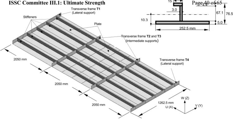
14.2 Reference panel description 40 14.3 Finite element modelling 41 14.4 Finite element analyses 43
14.4.1 Phase A - Calibration Assessment. 43 14.4.2 Phase A2 – Calibration with HAZ 44 14.4.3 Phase B1- Weld Types 44
14.4.4 Phase B2 – HAZ width (η) 45 14.4.5 Phase B3 – Initial Imperfection 46 14.4.6 Phase B4 - Residual Stresses 46 14.4.7 Phase B5 - Plate Thickness 47 14.5 Explicit Dynamic Analysis 47
14.6 Discussion 48 15. CONCLUSIONS 49 REFERENCES
1. INTRODUCTION
This is the report of the ISSC Technical Committee III.1 on Ultimate Strength covering the period from 2000 to 2003.
Despite its relatively long life, the area of ultimate strength is still being actively investigated and developed by practitioners and researchers worldwide. Indeed, many of the large maritime disasters that have occurred throughout the world over the past decade (Erika, Nakhodka, Prestige, P-36) are related to ultimate loads and strength. This type of public disaster will most likely continue to remind us about the importance of the field.
Accurate assessment of the ultimate strength of a structure is important not only for the initial design but also for the operation, maintenance, repair, and modification of the structure. The range of structures and materials for the initial design is obviously quite wide. When the types of in-service degradation are to be considered, the range of structures and loads becomes enormous. With approximately 250 papers and books referenced, the present report covers a good part of those configurations. But as it will appear, the growing demand for optimum structures throughout a structures lifetime makes plenty of room for improvements and expansions.
Chapter 2 outlines the fundamental ingredients of the area of Ultimate Strength. Chapter 3 discusses empirical and analytical methods. Chapter 4 covers numerical methods, i.e. mainly the finite element method but also advances in the alternative mesh-free methods and general solution techniques. Chapter 5 describes some new, interesting experimental methods of relevance to ultimate strength. Chapter 6 covers reliability methods. Chapter 7 discusses tubular members and joints, mainly of
interest for offshore structures. Chapter 8 covers work on stiffened and unstiffened plates which are the fundamental building blocks for ships. Chapter 9 covers shells, i.e. curved plate structures, which might be used in pipelines. Chapter 10 and 11 cover ship and offshore structures, respectively, i.e. the strength of a system composed of the components considered in the previous chapters. Chapter 12 and 13 cover ultimate strength issues for non-ferrous structures, i.e. composite and aluminium, respectively. Finally, Chapter 14 shows the results of a comprehensive study carried out by the Committee members with the objective to investigate the strength of welded aluminium panels subject to axial compression.
2. FUNDAMENTALS
2.1 General
The maximum load carrying capacity, here called the ultimate strength, is of relevance for • parts of a structure such as a stiffened plate, a tubular member or a joint,
• substructures such as a bulkhead, hatch cover or deck, or
• entire assembled structures such as a hull girder in bending or a steel jacket subjected to overturning forces.
Ideally, global ultimate strength should be achieved in a ductile and predictable manner. In practice this is difficult to achieve because elements of a structure might fracture in regions of high plastic strain in tension, or they might shed load rapidly as buckling occurs with some local yielding. Even if overall failure is less than fully ductile, it is important that components exhibit significant post-elastic deformation capacity.
Figure 1 Load-deflection characteristics of a structural element
Figure 1 describes typical load-deformation behaviour of a structural element. The hardening domain of behaviour which follows the initial elastic behaviour is important for redistribution of actions within a structure after yielding commences so that the structural elements share carrying the load more equally. If the weakest element fails too quickly then overall collapse can be triggered by a local failure. This is the tripping phenomenon of stiffened plate, which has the potential to cause overall collapse. For these reasons it is not sufficient to have a formula for ultimate strength of an element. The ductility characteristics must also be known. This is only possible with a combination of laboratory testing and historical analysis in the time domain.
Another reason for historical analysis is concerned with impact loading such as grounding and collision. In this case the load-deformation relationship is needed to determine the energy absorbed.
Load
hardening softening
Deflection maximum
Of course the value of the ultimate load capacity and confidence are vital questions for assessing the lifetime safety of a structure subjected to operational and environmental loads. Practical design requires knowledge of the ultimate load capacity and the degree of certainty with which that is known – typically represented by a probability distribution function, or at least data on standard deviation. Therefore one needs to know the sensitivity of the estimate of structural ultimate strength to variable factors affecting strength.
2.2 Types of Loading
It is appropriate to recall the types of load as stated in the 14th ISSC related to ultimate strength.
“Slowly” applied loads
The majority of loads to be considered fall into this category. These are environmental and operational loads due to wind, wave, current, cargo, drilling, etc., including inertial forces due to motion of the structure. The loading rates are slow enough for there to be no elevation of yield stress through high strain rates, or shock waves through the structure. There are generally statistical parameters regarding the distribution of these loads through the design life of the structure.
Cyclic loads
This is the case of repeated loads of high amplitude, relatively few in number, resulting in alternating or incremental plasticity. Such loads can arise from waves in a single storm, or an earthquake.
Dynamic (impulsive) loads
These are loads of duration less than or in the order of the period of vibration of the global or local structure at the point of impact. Wave slam and supply vessel docking forces are typical examples. Inertial forces are significant in mitigating maximum load effects, and elevation of yield stress due to high strain rates can be significant. An extreme case is impulsive loading due to explosion.
Crash loads
Major collisions and grounding accidents are examples of crash loads, which are covered by another ISSC Committee. In this case energy absorption is the most significant issue. Material strain rate effects, tearing, buckling, large plastic deformations, friction and ductile fracture are typically involved.
2.3 Forms of Collapse Single excursion failure
This is the case of collapse under monotonic loading established by time series analysis. It is the basic case for assessment of safety under operational and environmental loads. It includes the effects of nonlinear material and geometric behaviour, and the parameters affecting ultimate strength as listed below.
Cyclic failure
Load capacity under cyclic loading can be significantly less than the “static” strength under a single load excursion. Alternating plasticity can occur under fully reversed loading. Without accumulating visible permanent deflection the material subjected to alternating plasticity will rupture. It can be described as low cycle fatigue. Typical locations of such failures will be at discontinuities, such as misaligned butt welds in members and geometric discontinuities at joints. More often the loading is not fully reversible and incremental collapse occurs. Permanent deflections are seen to grow with each cycle of load until the structure becomes unserviceable or local ductility is exhausted at geometric discontinuities, resulting in fracture.
Crushing and tearing
This form of failure is typically associated with collision or grounding, where the load is, in fact, an accident. Here, the issue is energy absorption, and in the case of tankers, for example, integrity of containment.
2.4 Assessment of Ultimate Strength
Practical design is traditionally achieved by using simplified models of load and load effect, assuming elastic behaviour of the material, to be compared with simplified models of strength of both elements and the whole structure. These simplified models of strength are derived from extensive experimental, analytical and numerical studies where conservative combinations of imperfections, residual stress, thickness loss, etc., are assumed. Formulas for hull girder strength, stiffened panels, tubular joints, etc., are being refined as more and more studies are carried out, and as new materials and forms are considered.
However, as computational power increases, it is becoming feasible to contemplate direct analysis of ship and offshore structures combining computational fluid dynamics (CFD) with structural finite element modelling. For this reason, this report includes chapters on empirical, analytical, numerical and experimental methods. There have been significant advances in numerical modelling (for example finite element modelling, FEM) that have made it possible for a structural engineer to predict the ultimate strength of highly complex structures by non-linear modelling.
2.5 Sensitivity Assessment
Still, due to the complexity and uncertainties involved in ultimate strength predictions, any analysis – as well as this report – should include considerations regarding the sensitivity of the strength to
• material behaviour, such as material yield stress, ultimate strength, and strain hardening, • initial geometric imperfections and residual stresses due to welding and assembly, • plate thickness including thickness loss (from corrosion),
• mechanical damage resulting from service, for example fatigue cracks or impact dents, • loading rate, load introduction, alignment of actions, and boundary conditions.
Chapter 15 of this report by Committee III.1 contains an example of a sensitivity analysis of a stiffened aluminium panel continuous over three spans, subjected to axial compression.
Many more such studies are needed to establish the basis for a fully rational risk-based design.
3. EMPIRICAL AND ANALYTICAL METHODS
3.1 Needs for empirical and analytical methods
For an accurate estimation of the ultimate strength of structural members and systems, it is necessary to simulate the collapse behaviour considering the influences of yielding and buckling. In theory, the most versatile and accurate method to perform such an analysis is the FEM. However, incremental analysis is in general required, and this causes troubles related to computation time and memory in some cases. To avoid this, non-finite element methods are also used for strength analysis of ship structures. They can be grouped into two, which are empirical methods and analytical methods.
3.2 Empirical methods
Paik et al (2000a) derived empirical design formulas to evaluate buckling strength and ultimate strength of a rectangular plate subjected to general combined load on the basis of analytical and numerical results. In deriving the formulas, influences of initial imperfections, perforations etc. were considered. Paik and Thayamballi (2000) derived empirical design formulations to evaluate the local buckling strength of a stiffened plate by curve fitting on the basis of the analytical solutions considering the influence of constraint by stiffeners. Regarding the ultimate strength of stiffened plates, Paik and Kim (2002) derived advanced, yet design-oriented ultimate strength expressions for stiffened panels subjected to combined axial load, in-plane bending and lateral pressure assuming six patterns in collapse mode. These formulas were used by Paik et al (2002) to estimate the ultimate longitudinal strength of ship hulls.
For the perforated plate subjected to uni-axial thrust both in longitudinal and transverse directions, Yao
et al (2001a, 2002c) derived simple formulas to evaluate the elastic buckling strength and the ultimate
strength on the basis of the results of FEM analyses. Harada and Fujikubo (2001) also derived the empirical formulas for the same problem.
The average stress-average strain relationship for rectangular plates under uni-axial thrust was generated on the basis of the existing design formulas for both long and wide rectangular plates by Hu and Sun (1999). Hu et al (2001) used this relationship to evaluate ultimate hull girder strength of bulk carriers.
3.3 Analytical methods
Fujikubo and Yao (1999) derived an analytical formulation for accurate estimation of the elastic local buckling strength of a continuous stiffened plate subjected to bi-axial thrust considering the influences of plate/stiffener interaction and welding residual stress. The stiffener web was modelled by a plate, and very accurate buckling strength was obtained as indicated in Figure 2.
Figure 2. Comparison of predicted buckling strength with that by FEM (Stiffened plate with welding residual stress: σx, σy are buckling stresses and σY is yield stress). Fujikubo and Yao (1999). Murakami et al (2002) show an analytical formulation to simulate dynamical elastic secondary buckling accompanied by dynamical snap through. The analytical results showed good correlation with the FEM results. Cui et al (2002) generalised simplified analytical method to deal with ultimate strength of rectangular plates accompanied by initial deflection and welding residual stress under the combined bi-axial thrust, shear and lateral pressure loads.
Analytical and numerical methods are combined to simulate the elastoplastic large deflection behaviour of plates by Paik et al (2001b). That is, geometrical nonlinearity was treated by analytically solving the nonlinear governing equations of the elastic large deflection plate theory, while material nonlinearity is dealt with implicitly by using a numerical procedure.
To simulate the elastic/plastic buckling behavior of a simply supported rectangular composite plate subjected to edge compression, a theoretical approach based on the plastic theory has been developed by Soh et al (2000). For the analysis on composite laminated plates exposed to a combined loads, Yang and Zhang (2000) tried semi-analytical approach. In this approach, the formulations were based on the classical laminated plate theory (CLPT), and include the plate-foundation interaction effects via a two-parameter model (Pasternak-type) from which Winkler elastic foundation can be recovered as a limiting case.
Xue and Hoo Fatt (2001) used a five-plastic-hinge model to describe the non-axisymmetric post-buckling collapse of non-uniform circular ring subjected to external pressure loads. In the formulation, the principle of virtual work and upper bound theorem are applied to find the collapse pressure and collapse mode. The plastic hinge method was also applied in combination with geometrical nonlinearity by Kim et al (2002) to analyse the collapse behaviour of a space frame considering the influence of lateral torsional buckling. Tian et al (1999) performed a rigid plastic mechanism analysis to find the post-buckling response, and the Ritz method was applied to evaluate elastic buckling strength of shells with ring-stiffeners under general pressure load.
Hu et al (2000) simulated a tripping of stiffeners in stiffened panels subjected to combined loads on the basis of the Vlasov's differential equation for torsional buckling by applying the Galerkin's Method. In their formulation, a beam-column approach is employed taking into account the influence of panel local buckling on the constraint.
Paik et al (2001d) modelled a stiffened panel as an equivalent orthotropic plate, for which various elastic constants characterising structural orthotropies are determined in a systematic manner using classical theory of elasticity. The ultimate strength is determined from the condition that the highest edge stress reaches the yielding stress. The ultimate strength interaction relationships are also derived. Byklum and Amdahl (2002) derived analytical formulations to simulate elastic buckling and post-buckling behaviour of local panels in stiffened plating subjected to combined loadings. In their formulations, deflection of a panel is expressed as a sum of simply supported mode and clamped mode, both consisting of trigonometric series. The stiffener web is also treated as a plate but overall deflection of the stiffened plating is not considered. The calculated results showed good correlation with FEM results. The ultimate strength is defined as the initial yielding strength on the basis of the Von Mises’ yield condition.
Hopperstad et al (1999) applied the classical Stowell’s theory for plastic buckling to evaluate the ultimate compressive strength of aluminum stiffened plate in combination with the effective width concept, and with ultimate strength formulas recommended in the literature.
4. NUMERICAL METHODS
4.1 General
Numerical methods, such as the finite element method (FEM) and the mesh-less or particle method, have been an area of extremely active worldwide research for the last few decades. Therefore, it would be formidable task to review all published papers on the subjects (probably several thousand papers a
year). The focus of this chapter is only on some recent developments in FEM and mesh-less or particle methods for the ultimate strength assessment and non-linear analysis of the thin-walled structures.
4.2 Finite Element Method
Finite element simulations generally involve the solution of large sparse linear systems of equations for modeling in ever increasing detail geometrical and physical features. In order to meet such time and memory consuming demands for solving these equations, considerable research has been carried out for the application of parallel mathematical operations in a finite element analysis due to the widespread availability of parallel machines with large memory. Scott (2001) presented the development of the parallel frontal solver for finite element equations based on dividing the finite element domain into subdomains and applying the frontal method to each subdomain in parallel. Farhat et al. (2000) present the newly developed transient finite element tearing and interconnecting (FETI) methods and their application to the parallel analysis of large-scale linear and geometrical nonlinear structures. The numerical examples show that the present FETI method operates more efficiently on large numbers of subdomains and offers greater robustness, better performance, and more flexibility for implementation on a wider variety of computational platforms.
It is generally recognized that the return mapping algorithms, such as the radial return method, the closest point projection method and the spectral return-mapping method are robust and efficient for large inelastic computations. Lof et al. (2001) propose an adaptive return mapping algorithm for the integration of elasto-viscoplastic constitutive equations based on a combination of the beginning and end of the increment. Lee and Fenves (2001) present the stress updating formulation and consistent tangent modulus for rate-independent plastic-damage models on the basis of the spectral return-mapping algorithm. The equations were expressed in terms of the principal stresses and plastic multiplier in the spectral return-mapping scheme and the update stresses and plastic strains as well as the scalar parameter for damage are obtained by solving a nonlinear scalar equation.
Error control and adaptive algorithms play an important role in improving the approximation behavior of FEM. The error estimation and adaptive mesh generation were initially proposed in the 1970s for estimating the discretization error resulting from finite element analysis of linear problems based on residual and average error criteria. Subsequent studies on adaptive FEM based on error estimation were extended to include consideration of geometrical and material nonlinearities. Ladeveze (2001) developed a posteriori error estimators based on constitutive relation residuals, in which the classical error sources such as the space discretization, the time discretization and the iterative technique are included. Lopez (2001) presents an asymptotic predictor-corrector algorithm based on residual error minimization for tracing the equilibrium path of geometrically nonlinear plates and shells. Mang et al. (2001) present the practical application of adaptive FEM in ultimate load prediction of reinforced concrete shells. Askes and Rodriguze-Ferran (2001) propose a so-called rh-adaptive approach in order to combine the advantageous properties of both r-adaptive and h-adaptive strategies. It is performed by means of splitting the domain under consideration into two subdomains and the h-adaptive scheme is employed in one subdomain whereas the r-adaptive approach is used in the other subdomain. Duster et al. (2001) present an implementation of a three-dimensional p-adaptive FEM for curved thin as well as thick walled structures based on a hexahedral element formulation and the blending function method. Hand and Wriggers (2000) derived an error indicator for h-adaptive analysis of elastoplastic shells based on the super-convergent patch recovery procedure.
Another great important issue in FEM is the element model. Iintensive research efforts have been devoted and different techniques have been used to develop “simple, robust, generalized, extended, refined, efficient, modified, …” element models. Kolahi and Crisfield (2001) present a large strain
elastoplastic shell formulation based on the co-rotational description of the faceted Morley triangle. The obtained formulation is invariant to the node numbering by re-visiting the origins of the Morley triangle and re-casting the formulation as a special form of discrete Kirchhoff approach. Levy and Gal (2001) introduce a new approach to the geometrical nonlinear analysis of shells by perturbing the equilibrium equations. All contributions to the response of the same order of magnitude are included. Zielinski and Frey (2001) discuss the transformation and linearization of the finite element equations and present the expressions for the tangent matrix in the framework of the Total Lagrangian, Updated Lagrangian and co-rotational formulations.
Wang and Theirauf (2001) propose the two modifications for the finite rotation formulation and for the rotation update scheme in order to avoid the singularity of the rotation update procedure and improve the numerical stability of the iterative solution algorithm. Ibrahimbegovic et al. (2001) developed alternative parameterizations for constrained finite rotations in terms of the chosen rotation vector. The modification of finite rotation expression leads to a symmetrical tangent stiffness matrix and the simple implementation of the proposed additive iterative updates. The other typical research activities were the works of Hauptmann et al. (2000) on the application of the solid-shell concept for nonlinear analysis of large elastoplastic deformations and the works of Maccarini et al. (2001) on the nonlinear finite element formulation for shells of arbitrary geometry.
In recent years, the rotation-free shell element models have attracted considerable attention, in which the curvatures over an element are approximated in terms of the deflection of the nodes in a surrounding patch of elements. It leads to several advantages of the rotation-free shell elements, such as it becoming unnecessary to process finite rotational increments in nonlinear analysis, compared to the conventional shell elements with both translational and rotational degrees of freedom. Onate and Zarate (2000) present a general methodology for deriving rotation-free thin plate and shell triangular elements based on the combination of the standard finite element interpolation with finite volume concepts. Flores and Onate (2001) made an extension to nonlinear analysis of plates and shells by using an updated Langrangian formulation and elastic plastic model. The element performance is better than that of conventional triangular elements for linear problems in terms of the degrees of freedom. Very good results have been obtained in several examples including large displacement and large strain problems.
Motivated by the significant progress in computer-aided geometrical design, Cirak and Ortiz (2000) developed a so-called subdivision element model for thin shell analysis based on the subdivision surface concept. The element energy is given by a direct evaluation of the Kirchhoff-Love energy function. However, it is different to conventional element interpolation, as the displacement field of the subdivision element is interpolated from nodal displacement only and does not need nodal rotations. The displacement field within the subdivision element is dependent not only on the displacements of the nodes attached to the element but also on the displacements of all the immediately adjacent nodes in the triangulation. Recently, Cirak et al. (2001) extended the subdivision element to nonlinear shell analysis accounting for finite membrane and bending strains as well as thickness stretching and large deflections.
4.3 Mesh Free Method
Research efforts have recently been directed to eliminating or at least easing the requirement for meshing the domain to be analyzed. Most mesh-free methods do in fact need a mesh for the integration required in the principle of virtual work, so ‘mesh-free’ only refers to the fact that the spatial interpolation is carried out without a mesh. The interpolation functions are related to a node (a particle), which extend in all special directions and are therefore not confined to an element.
Comprehensive overviews of the theory and application of mesh free methods can be found in Belytschko et al (1996) and Li and Liu (2002).
The methods usually suffer from an important computational cost. Therefore, a combined approach based on coupling of FEM and mess-less or particle method is expected to achieve cost-effective procedure for practical application as discussed by Huerta and Mendez (2000).
The element free Galerkin method (EFG) was developed by Krysl and Belytschko (1996) for numerical analysis of the thin plate/shell based on Kirchhoff theory. It was extended by Donning and Liu (1998) to the analysis of moderately thick/thin beams and plates by using Mindlin-Reissner theory. Good convergence was achieved by using moving least-square interpolation functions and cardinal spline interpolation functions respectively. Recently Noguchi et al. (2000) enhanced EFG to deal with three-dimensional general shell and spatial structures by mapping the geometry of arbitrary curved surfaces in the two-dimensional space. The total Lagrangian formulation is employed to process the geometrical nonlinear behavior and the bi-cubic and bi-quadratic basis functions are adopted in the moving least square interpolation. Leitao (2001) proposes a mesh-less method for the approximate solution of the Kirchhoff plate problem based on the radial basis functions. The governing equations and the boundary conditions of the plate are satisfied at selected points by using the Hermite collection method. The formulation of this EFG method is straightforward and is similar to the degenerated approach in the FEM.It is also very simple to implement, computationally efficient and expected to be useful for more practical applications in engineering problems.
Yagawa and Furukawa (2000) presented a free mesh method (FMM), which is performed on a node-by-node basis without the global meshing. The FMM represents the domain to be analyzed in the discrete form of the appropriate allocation of nodes for creating local elements with a prescribed radius. The local elements are performed at each node in an autonomous manner according to the nodal information. The modifications of FMM have been proposed by Furukawa et al. (2000) with quadrilateral elements instead of the triangular elements to improve the accuracy of simulation. The FMM has good compatibility with parallel computers because its nodal information can be individually distributed to processors and the local elemental equations for each node are all constructed and analyzed in the processors independently. The significant advantage of FMM in comparison to other mesh-less methods is the reliability of its solution as the construction of the global equations is based on FEM, which has a documented level of accuracy.
4.4 Idealized Structural Unit Method (ISUM)
The ISUM can be regarded as a kind of FEM, but the elements (structural units) used in ISUM are usually more sophisticated and a larger part of the structure is considered as an element when it is compared the ordinary FEM. The theoretical background and the development of the ISUM were
well explained by Ueda (2000). According to this, ISUM can be divided into two categories, which are ISUMs of the first generation and the second generation. ISUMs of the first generation were based on the empirical formulations derived from the observations of the experimental and numerical/theoretical results, while the second generation is on the basis of mathematical approximations.
The ISUM of the second generation could be said to be a very sophisticated method, but at present it still fails to simulate the actual collapse behavior accompanied by the localization of plastic deformation at a certain region and the resulting elastic unloading at remaining regions in the post-ultimate strength range. This is because a periodical deflection mode such as a buckling mode is assumed for the shape function of the element even beyond the ultimate strength. To overcome this
problem, Fujikubo et al. (2000a) developed a new shape function for the lateral deflection of ISUM rectangular plate element. They proposed a new lateral shape function, which consists of two deflection terms on the basis of the characteristic deflection modes, observed in the collapse simulation by FEM. The ratio of the two deflection terms changes depending on the average strain. The applicability and the favorable accuracy of the newly proposed ISUM element have been demonstrated through comparison of the calculated results by ISUM and FEM analyses. Figure 3 shows the comparison of the element representation by FEM, ISUMs of the first and the second generations and new ISUM for the case of a rectangular plate subjected to longitudinal thrust.
Figure 3. Comparison of element representations by different methods of analyses (Rectangular plate subjected to longitudinal thrust). Fujikubo et al. (2000a).
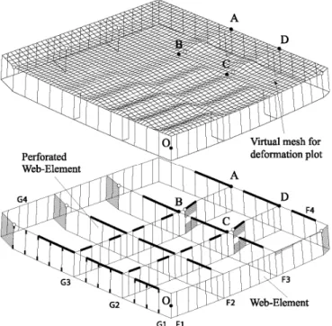
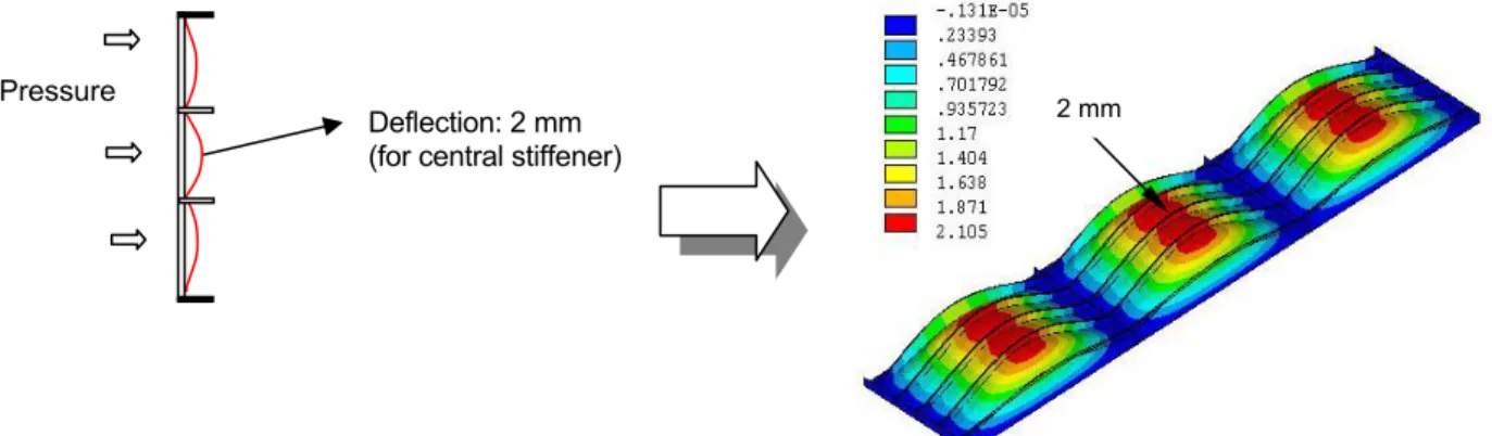
Fujikubo et al. (2000b) extended this ISUM element with a new modeling technique to evaluate overall buckling of stiffeners with attached plating as well as local buckling of plates. The collapse behavior of stiffened plate under bi-axial thrust as well as uni-axial thrust is simulated by this ISUM plate element in combination with a beam-column element. Kaeding and Fujikubo (2001) used this new ISUM element to simulate collapse behavior of a VLFS. Recently, Fujikubo et al. (2002) developed new ISUM elements to analyze the collapse behavior of double bottom structures. Large plate elements and beam-column elements are used for inner and outer bottom plating and stiffeners, respectively, and Timoshenko beam elements for webs of girders and floors. All the elements can simulate buckling/plastic collapse behavior. With these elements, fundamental collapse modes with localized failures in double bottom structure were obtained under pressure loads, see Fig. 6 in Chapter 11.
5. EXPERIMENTAL METHODS
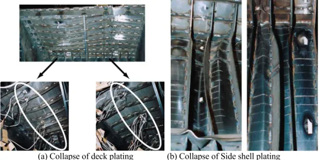
Due to the complexity of the phenomena involved in the prediction of ultimate strength, experiments will continue to be important for development and validation. Experiments should here be understood as conventional laboratory experiments as well as in-service and inspection monitoring. In addition to the specific methods listed in this chapter, examples of experiments will be presented in Figures 4, 5, 6 and 8.
5.1- Resonance Thickness Measurement (RTM)
Resonance Thickness Measurement (RTM) has been developed by Det Norske Veritas and Kongsberg Defence & Aerospace. The RTM method is based on the time an ultrasonic wave takes to travel
through the thickness of a steel plate and return to the receiver. The technique effectively performs an integration over the area insonified by an acoustic pulse and over the frequency band of interest, yielding a measure of re-radiated energy in a given frequency band. The result can be directly translated into an estimate of the thickness within the insonified area. The acoustic technology may also be employed with other purposes, like determining whether corrosion is on the inside or on the outside of a pipe. This is enabled by the exact determination of the distance from the transducer's face to the reflecting surface.
There is also a very good signal-to-noise ratio for the RTM, that insures a good repeatability of the measurements. The reflected pulse is a result of the environmental influence upon the emitted pulse and it holds all the information about that environment. The receiving transducers and the processing software extract the desired values from the received pulse. A notable point is that the lower frequency range from RTM enable the signal to pass through graphitic and rust corrosion, in contrast to standard ultrasonic methods.
So far, the method was tested by DNV with good results, also on cast and ductile cast iron pipes. It was shown that the presence of rust does not affect the estimate of the steel thickness. Unfortunately no literature on the subject is made public at present.
5.2- Ultrasonic Stress Measurements
Research efforts have been invested in ultrasonic stress measurements during the last decade. Ultrasonic measurements are not only used to determine the thickness, but also for stress measurements. The ultrasonic methods are based on the stress sensitivity to ultrasound wave speed through the solid, Schneider (1997). Dependency is established using the Poisson ratio and Lame's material constants.
Noise factors can influence the measurement results because the stress-induced changes in the wave velocity are quite low. Material grain orientation, also known as texture, and the temperature are of great importance. Material acoustic constants are determined prior to the measurements. The calibration phase normally takes place using a free stress specimen.
Ultrasonic methods provide a measure of the macro stresses over a material volume. They are quick to implement, and are generally considered to be an attractive engineering tool. These methods are suitable for stress measurements in shipbuilding steel plates, thus providing important information about the plate buckling reserve.
5.3 - Strain Measurements with Thermovision
Thermovision is a new method used for the strain analysis of loaded steel members even into the plastic range, Pasternak and Müller (2002). It enables the visualization of the strain under variable loads. In this method, a high resolution infrared camera is employed to scan the heat radiation at the surface of the loaded structural member. A change of load will affect the heat radiation almost simultaneously.
The main principle behind the method is the transformation of the internal energy into heat that takes place especially by the plastic straining of the material. It enables the strain examination beyond limitations imposed by strain gauges. Moreover, the thermo-vision allows the strain visualization over an area, not only at a point, thus providing valuable information about the strain gradient. It should be noted that the thermal properties of surface coating are important, as they could prevent a proper scanning.
Infrared cameras are becoming less expensive, as well as being available nonmilitary applications. Dimensions of the domain to be studied are indeed limited by the possibilities of the camera, so the critical regions are to be localized and observed from the beginning.
6. RELIABILITY
This chapter addresses published research on the ultimate strength reliability of structural components and systems of ships and offshore structures.
In reliability analysis, limit state functions are normally expressed by the difference in capacity (resistance) and load effect. Therefore determining the uncertainties of capacity and load effect is very important. Uncertainties relating to load effect will be considered in other committees. Only the uncertainties of capacity will be discussed in this section.
In the structural analysis of ships, the analysis is conventionally divided into three different levels, namely primary strength, secondary strength and tertiary strength. This was initially proposed for deterministic analysis. The same idea is also used in reliability analysis. Tertiary strength is concerned with the strength of local components, such as openings, and mainly about fatigue performance. So it is out of the scope of this committee. The reliability of ultimate strength of only stiffened panels (secondary strength) and hull girder (primary strength) will be discussed here.
6.1 Ultimate Strength Modelling Bias and Uncertainties
Prediction of uncertainties involved in structural design is an important part of structural reliability analysis. Quite a few of publications were reviewed in the last ISSC report, but there are not many papers on this subject in this period. Soriano et al (1999) have presented the biases and uncertainties of foundation capacity along with metocean parameters, wave forces and tubular joints of offshore platforms.
Cui et al (2001) have proposed a method for calculating the mean and standard deviation of a function of random variables. In this method the mean and standard deviation of a function are calculated by a set of formulae, in which the mean and standard deviation of each random variable are used. The method has an accuracy of at least the second order Taylor series solution. New definitions of sensitivity factors were introduced. The uncertainties of ultimate strength of a stiffened panel were then estimated by this method.
In addition to their work reported in last ISSC’2000, Rigo et al (2001) presented more results on the uncertainties in prediction of ultimate hull bending moment using progressive collapse analysis. Several methods were used to generate average stress-strain curves of stiffened panels. The effects of these curves on the ultimate strength of hull girder were systematically investigated. In recognition of the importance of average stress-strain curves in ultimate hull girder strength prediction, Pradillon et al (2001) have carried out a comparative study for the prediction of ultimate strength of stiffened panels. Eighteen methods for predicting ultimate strength of stiffened plates were studied. Multi-criteria were used to assess these methods. Those methods that can quickly produce average stress-strain curves were further compared. The effects of these stress-strain curves generated by different methods on the ultimate strength of a box girder were demonstrated.
6.2 Ultimate Strength Reliability Analysis
In reliability analysis of plates, analytical formulae for ultimate strength prediction, which are validated by experimental data, can be conveniently used. All the reliability methods, especially first order and second moment (FORM), can be applied for this type of analysis because the limit state functions are explicitly expressed. But if more sophisticated methods are adopted for predicting the capacity of plates, such as non-linear finite element methods, the limit state function has implicit form. In this case, FORM is arguably not suitable, so other methods have to be used. The response surface method is considered as a good candidate.
Kmiecik and Guedes Soares (2002) applied a response surface method to determine the probability distribution of ultimate strength of plates. A linear response surface of the ultimate strength of unstiffened plates under compression was constructed based on the results of non-linear finite element prediction. The mean values of ultimate strength from the response surface method agree well with those from Monte Carlo simulation, but the standard deviations differ quite a lot. This methodology can be used when there is not an explicit limit state function in reliability analysis. Zheng and Das (2000) carried out a reliability analysis of a stiffened plate using a new response surface method. In the analysis, the critical bucking of the plate was considered and predicted by the commercial finite element analysis package ABAQUS. These results were used to establish a failure surface function. In the proposed response surface method, a linear response function was first developed. The second order terms were then added to improve the accuracy.
A series of reliability analyses were carried out to determine the allowable imperfection tolerance of unstiffened plates under uniaxial compression, Mansour and Elsayed (1999). The ultimate strength of unstiffened plates was predicted by a simplified formula, in which initial deflection and residual stresses can be considered. Reliability analysis was performed under the assumptions that both resistance and applied stresses are normally distributed with a coefficient of variation of 10%. The allowable imperfection tolerance was presented as a function of plate slenderness.
In the reliability analysis of hull girder the way to predict hull girder failure could be classified into two categories:
(1) using an analytical formulation to predict the strength. Hence FORM can be applied to these cases.
(2) using progressive collapse analysis to predict the ultimate strength of hull girders. Even in this category, there are variations in how to carry out reliability analysis. One way is to calculate the mean value of the ultimate strength by a progressive collapse analysis method, and assume the c.o.v. of the ultimate strength is about 10-15%. In this way, FORM can be used for reliability analysis. The other way is to integrate a progressive collapse analysis method into a reliability analysis method. The limit state function then has implicit form.
The failure probability of bulk carriers was predicted for two different structural arrangements, namely single hull and double hull forms, Guedes Soares and Teixeira (2000). In the calculation of reliability index, a first order and second moment method was used. The extreme values of stillwater bending moment and wave-induced bending moment were adopted. An empirical formulation was used to consider the difference between sagging and hogging bending moment. The ultimate strength of the hull girder is used as measure of the failure of the ships. The uncertainty of ultimate moment was counted by using a model uncertainty factor with a mean of unity and a c.o.v. of 15%. The results show that the reliability of the double hull ship is higher than that of the single hull ship. In addition, the effect of corrosion on the reliability of the hull girder was also assessed. The paper also shows the dependency of predicted reliability on the definition of applied loadings.
A reliability analysis was carried out to predict the failure probability of floating production storage and off-loading systems (FPSO) by Maerli et al (1999). The ultimate strength of the hull girder was estimated by Lloyd’s program LRPASS. The Ferry Borges-Castenheta load combination method was used to evaluate load combination factors for combining stillwater bending moment and wave-induced bending moment. Three different FPSOs were assessed. Their reliability indices were compared with those recommended by DNV rules. A similar methodology was applied to predict the reliability of a naval vessel by Das and Dow (2000). Instead of using Lloyd’s program LRPASS, a non-linear analysis program, FABSTRAN, developed by Dow and Smith (1986) was used to generate average stress-strain curves of stiffened plates.
A procedure for predicting the reliability of hull girder was proposed by Downes and Pu (2002). In this procedure, a Monte Carlo simulation method was used to predict the failure probability, and a Lloyd’s register’s program, LRPASS, for calculating average stress-strain curves of each stiffened panels was integrated into the program predicting ultimate hull girder strength by Smith’s method in such a way that the stress-strain curves could be interactively generated.
Masaoka et al (2000a) reported on reliability analyses of ship hull girders. Smith’s method was used to evaluate the ultimate strength of hull girders, in which the average stress-strain curves of structural elements were obtained from a database based on non-linear finite element analysis. The mean value and standard deviation of ultimate strength was estimated by Monte Carlo simulation with 100 samples. The reliability of the hull girder was then calculated by a FORM method. A similar method was applied to a very large floating structure (Masaoka et al, 2000b). The reliability index of the structure under different wave heights was calculated. The sensitivity factors of reliability with respect to yield stress, plate thickness and loading were also presented.
Incecik and Pu (2001) have assessed structural strength of FPSOs by both deterministic and probabilistic methodology. In the context of reliability analysis, the failure probability of FPSOs in three failure modes, namely ultimate strength of the hull girder, initial yielding of the hull girder, and ultimate strength of stiffened plates, was predicted by a first order second moment method.
Yang et al (2001) have applied fuzzy reliability analysis to ship longitudinal strength. Three failure modes, namely initial yielding of the hull girder, torsional/flexural buckling of stiffeners, and ultimate bending strength of the hull girder, were considered. The ultimate bending strength was predicted by an empirical formula. The reliability analysis was carried out by using the first order second moment method. Fuzziness in both resistance and load effects was included in the analysis.
Sun et al (2000a,b) have carried out a reliability analysis of hull girder strength considering corrosion and fatigue. Ultimate hull girder strength was used as the measure of ships’ strength. Corrosion is assumed as a random process with a constant mean value. Coating life is modelled by a Weibull distribution. Crack propagation is evaluated by Paris-Erdogen equation. Only global vertical bending moments were considered in the prediction of crack propagation. A response surface method was used to generate the limit state function and a Monte Carlo simulation-based method was adopted for predicting failure probability. This methodology was applied to a bulk carrier in this paper and further applied to a FPSO in Sun and Bai (2000). A similar procedure was applied to ships used in the ISSC-2000 benchmark study by Sun and Bai (2001). The differences from the previous methods are: (a) the hull girder ultimate strength was predicted by a recently derived analytical formulation which agrees well with other methods, and (b) a three-stage process was introduced to model the corrosion, in which the coating effectiveness was considered. Further work on reliability of corroded and fatigue damaged ships was presented by Guedes-Soares and Garbatov (1999a,b).
The reliability analysis of damaged ships due to collision and grounding was carried out by Qi et al (1999). The ultimate residual strength of a hull girder was predicted by an analytical formulation, in which the damaged sections were removed. The reliability was calculated by an importance sampling method.
A structural system reliability approach was applied to predict the reliability of ultimate hull girder strength and sensitivity factors by Okada et al (1999). Both plate and beam elements were used to model the midship cross section. The dominant failure path was identified by this approach.
Two reliability analyses of structural strength are discussed by Hess (2002) in support of quantitative measurement of ship structural performance. The first analysis is the Monte Carlo simulation prediction of the reliability of a composite, sandwich panel subjected to a dynamic, lateral pressure load, with failure defined as first-ply failure. Coupon test data for glass-reinforced polyester from five different fabricators were used to develop the basic variable uncertainty information to demonstrate the impact of fabrication choices and subsequent material property characterization on the performance of the structure. The second analysis is the advanced second moment method reliability prediction of a combatant hull girder against ultimate strength and subjected to vertical, wave bending moments from an extreme mission. The hull girder bending strength prediction was performed using the US Navy code ULTSTR, and a 10% coefficient of variation was applied based on Monte Carlo simulations. Reliability analysis of composite plates under uniform lateral pressure and a central point load was carried out by Lin (2000). Stochastic finite element method, first order second moment method and Monte Carlo method were used, and first-ply failure was considered as failure for the composite plates. Four different failure criteria were adopted for deriving limit state functions in the analysis. It was concluded that both stochastic finite element method and FORM can predict reliability with reasonable accuracy. The same stochastic finite element method was applied to a composite plate under uniform lateral load by Lin and Kam (2000).
Monte Carlo simulation was applied to predict the reliability of a simply supported composite plate under lateral pressure, Jeong and Shenoi (2000). The first-ply failure was treated as the failure of the plate. Different failure criteria, such as maximum stress and Tsai-Hill criteria, were used in the reliability analysis. In addition, sensitivity analysis was also carried out to identify the importance of each variable. This work was further extended to use both first order second moment method and Monte Carlo simulation method to predict the failure probability of a composite plate, Jeong and Shenoi (2002). The accuracy of these two methods was compared.
For a redundant structure, the failure of a component does not necessarily lead to collapse of the whole structure, so structural system reliability methods should be ideally used. This is particularly true for offshore structures, such as jacket platforms, which have quite high redundancy. Structural system reliability methods for offshore structures have been reviewed by Onoufriou and Forbes (2001). The major uncertainties in predicting resistance of offshore platforms are identified. The areas, which need further development, are recommended.
A comparative study was reported by Dier et al (2001) on the reliability predictions of representatives of jacket and jack-up platforms. It was found out that the predicted reliability index was significantly affected by the adopted foundation modelling. The reliability index was reduced if the foundation failure was considered by a refined method. The jacket and jack-up platforms have a similar level of reliability. Morandi et al (2001) have pointed out the implicit and explicit safety reserves in various design codes for jack-ups and their impact on the reliability. The effects of other important factors on the reliability of jack-ups, such as environmental loading prediction, loss of air gap and deck inundation, etc, were also discussed. The author believes that some inherent features of jack-ups, which
were not considered in the reliability analysis, make them safer than what is reflected in the predicted reliability index.
Talavera et al (2001) have proposed a procedure for reliability analysis of very large floating structures. A simplified hydroelastic approach was used to predict the dynamic stresses in the structure. Reliability of the structure was then evaluated by a first order and second moment method. In the analysis only the buckling and ultimate strength of deck or bottom were considered.
Structural reliability analysis was performed on a very large pontoon-type floating structure together with a surrounding gravity-type breakwater by Fujikubo et al (2001). Failure modes considered in the analysis include ultimate bending and shear strength of the floating structure and overturning of the breakwater. The ultimate bending strength and shear strength were evaluated by both the idealised structural unit method and finite element method.
6.3 Ultimate Strength Reliability-Based Design And Optimisation
Reliability-based design of five ships was reported by Xu and Cui (2001). Both ultimate strength of hull girder and stiffened panels were considered in reliability analysis. The ultimate strength of hull girder was evaluated by an empirical formulation, which is based on the prediction of the ultimate strength of stiffened panels. The reliability analysis was carried out by the first order second moment method. Partial safety factors of five different ships were derived. These ships were redesigned to achieve the target reliability index.
7. TUBULAR MEMBERS AND JOINTS
7.1 Tubular members
A number of papers have been published related to ductile collapse of members and girders. Most relate more to a civil engineering application than to ship and offshore structures. Nevertheless some of the conclusions should be applicable in both fields.
An overview of Eurocode 3 Part 1.5 Design of Steel Structures is given by Johansson et al. (2001), focusing on tall girders and planar plated structures without transverse loading, typically applied in steel bridges and similar structures. The paper presents the background and justification of some of the design rules with focus on the ultimate limit states. Lindner (2000) discusses stability formulae for structural members, comparing theoretical solutions according to second-order theory with simplified formulae in Eurocode 3 and DIN 18 800. Special attention is given to the support conditions of the members and to lateral–torsional buckling. Alternative beam-column interaction formulae based on second-order in-plane elastic theory are proposed by Boissonnade et al. (2002), showing an extensive comparison with more than 15,000 results of finite element numerical simulations. Hasham and Rasmussen (2002) present a study of the strength of thin-walled I-sections in combined compression and major axis bending. Nonlinear finite element analysis is used to produce interaction curves for four cross-sections covering the range from slender to compact. For each cross-section, interaction curves are produced for four overall slenderness values including short and long beam-columns. The interaction curves are compared with design strengths obtained using the AS 4100, AISC LRFD, and Eurocode 3. The design strengths are shown to be generally conservative, particularly for slender cross-sections. Improved design interaction curves are proposed.
Chung and Lawson (2001) discuss the design of beams with large rectangular and circular openings. This paper presents the design method in the format of Eurocode 4, and presents general information
on sizing of openings as a function of the utilisation of the shear and the bending resistances. The effect of these openings on deflections is estimated by a simple factor that is dependent on the size and the location of the openings. Typical design tables for composite beams with large rectangular openings are presented. Chung et al. (2001) examine steel beams with circular web openings based on analytical and numerical studies, and suggest an empirical shear moment interaction curve for practical design of steel beams with circular web openings.
Kwak et al. (2001) present theoretical formulations for geometrically nonlinear analysis of three-dimensional beams with thin-walled open sections. The displacement field is described based on a total Lagrangian formulation, and the warping degree of freedom is taken into consideration to simulate the structural behaviour of slender or curved beams with an arbitrary shape. Static condensation is used to reduce the warping degree of freedom from the global stiffness matrix, and an improved arc-length method is used to overcome numerical instability in snap-through buckling analysis. Finally, correlation studies between analytical results and other previous numerical studies are presented to establish the validity of the proposed numerical approach.
Ronagh et al. (2000a, b) present a theoretical formulation for the nonlinear analysis of thin-walled beam-columns whose cross-section is tapered. An expression for the first variation of the Total Potential is derived, that may be used in a nonlinear equilibrium analysis, and an expression for the second variation of the Total Potential is derived, that may be used in a stability analysis. These variations are used as the basis for a finite element formulation. The resulting finite element formulation is then used to investigate the linear stiffness behaviour of a tapered beam subject to a torque, classical stability analyses of tapered members and the stability of tapered members when subjected to the effects of initial bending curvature. Where possible, comparisons are made with other solutions in the literature, and it is shown that the numerical model presented in this paper is very accurate.
Elchalakani et al. (2002a) present a theoretical formulation to predict the moment-rotation response of circular hollow steel tubes of varying D/t ratios under pure bending. The formulation includes the effect of ovalisation along the length of the tube, plasticity and local buckling of the tube wall. Two local plastic mechanisms are studied to model the local buckling behaviour, especially during the unloading stage. The theoretical predictions are compared with experimental results (Elchalakani et al., 2002b). Good agreement is found between the theoretical predictions and experimental moment-rotation responses. A closed-form solution is presented, suitable for spreadsheet programming. Ovalisation effects of tubular members is also considered by Karadeniz (2001), who presents a simple method for including ovalisation effects into the stiffness matrix of 3D FE analyses.
The dynamic behaviour of tubular steel members subjected to impact damage is investigated by Zeinoddini et al. (1998, 1999, 2000). They present results from numerical studies, closed analytical solutions and experimental tests showing that axial pre-loading has a marked effect on the lateral collapse load of the member, and on the level of energy that the member can absorb prior to collapse. Experiments are done on the tubes impacted by a dropped object with a velocity of about 7 m/s at their mid-span. Ruggieri and Ferrari (2002) present an experimental and numerical investigation of the structural behavior of a dented tubular member under lateral load.
Langhelle and Amdahl (2001) present results from an experimental investigation of the behaviour of AA 6082 alloy aluminium columns at elevated temperatures. Particular emphasis is put on high temperature creep effects. Tensile tests provide information for the material model of aluminium applied in the nonlinear finite element programs. 31 column buckling tests are performed for validation of the material models in nonlinear finite element programs and for evaluation of design rules. The column buckling tests are compared to numerical analyses and design rules predictions.
Watanabe et al. (2000) present an experimental study of multi-directional earthquake loading on rectangular hollow steel columns. Earthquake loading is in reality complex and multi-directional, as opposed to the conventional uni-directional approach. Thus, the experimental study investigated the effects of multi-directional load histories on the response of tubular columns commonly used in the construction of elevated highways and building structures. Test results indicate that, in comparison with uniaxial displacement paths, multi-directional displacement patterns lead to significant degradation in stiffness, strength and ductility of tubular columns.
Brooker and Ronalds (2001) present a continuum damage mechanics (CDM) model to represent ductile failure in nonlinear FE analyses. The model uses a CDM based relation to describe the dependence of the failure strain on stress state, and simulates element failure via material softening. The applicability of the model in presenting the first onset of failure is demonstrated by comparing finite element predictions with experimental results taken from the literature.
Kim and Kang (2002) present results from large-scale testing of a 3D, two-story, single-bay, and sway allowed frame subjected to non-proportional vertical and horizontal load. Details of the test frame, test instruments, set-up and test procedures and the load–displacement curve of the test frame are presented. Non-linear numerical analysis is also performed, and the results compared with the experimental results. It was observed that the load carrying capacity calculated by the AISC-LRFD method is 28% conservative when compared with that by the experiment, due to inelastic redistribution of moments in the frame.
Avery and Mahendran (2000) present test results and numerical methods for steel frame structures comprising non-compact sections. A series of large-scale tests are reported to provide experimental verification of the analytical models. The test frames exhibited significant local buckling behaviour prior to failure. The paper presents details of the test program including the test specimens, set-up and instrumentation, procedure, and results. Al-Shawi (2001) investigates the behaviour of circular hollow sections under large rotations, which cause ovalisation of the cross section and reduction of the plastic section. It is found that the reduction in the theoretical plastic moment of resistance can be significant, and this is confirmed by experimental evidence. Earls (2001) studies the structural ductility of high-performance steel I-shaped beams. It is observed that current cross-sectional compactness and flange- bracing limitations may not be directly applicable to these types of high-performance steel flexural members.
A number of other papers have been published on non-linear formulations and analyses of frame structures. More details can be found in Hsiao and Lin (2000), Liew and Tang (2000), Liew, Chen, Shanmugam and Chen (2000), Chen, Liew and Shanmugam (2000), Tomka (2001), Kim, Park and Choi (2001), Kim and Choi (2001), Kim, Park and Choi (2001a, b), Kim, Choi and Ma (2003), Huh, Kim and Kim (2001), Rodrigues and Jacob (2001), Srirengan, Chakrabarti and Ghosh (2002), and Pinna and Ronalds (2002).
7.2 Joints
MSL Engineering (2000) has carried out a major Joint Industry Project on assessment criteria, reliability and reserve strength of tubular joints. Phase I of the JIP has dealt with two aspects of joint technology (Dier and Lalani, 1998). Firstly, it has produced assessment criteria for joints under uni-axial loading, with better reliability than previous codes. Implicit in this is the effect of chord loading which was not well captured in previous criteria. The results of this part of the work has been included in ISO 13819-2. Secondly, Phase I concentrated on the development of complete non-linear load-deformation formulations for joints under uni-directional loading. The load-load-deformation
characteristics are given by closed-form equations for the complete P-δ or M-θ curves for T/Y, DT/X and K/YT joints subjected to axial, IPB or OPB loads. The equation coefficients, for a given joint classification, are simple functions of the non-dimensional joint parameters β, γ, θ, g etc.
Phase II of the JIP (MSL Engineering, 2000; Dier and Hellan, 2002) has extended the previous developments by establishing yield and ultimate failure envelopes for multi-directional loading, also incorporating chord load interaction. The resulting formulations have been codified into a generic joint module for use in non-linear frame analysis packages adopted in the offshore industry. The joint module has been developed and integrated as part of the USFOS system.
8. PLATES AND STIFFENED PLATES
8.1 General
Plates and stiffened plates are the dominating structures in all ship and offshore applications and steel is the dominating material used. Consequently the ultimate strength of these structural elements has also been actively studied and all ISSC reports give specific emphasis on this topic. The recent developments in non-linear numerical analysis methods enable nowadays fairly accurate analysis of the collapse behaviour of local structural elements. The main topics under active research are: modelling of post-weld initial imperfections, effect of end conditions such as rotational restraints and torsional rigidity of support members, and the effect of combined loadings such as biaxial compression/tension, edge shear and lateral pressure. In chapters 3 to 5, the analytical, experimental and numerical analysis are discussed in general, whereas here the emphasis is summarising the work related more on the practical applications developed for plates, stiffened panels and steel sandwich panels.
Paik and Thayamballi (2002b) give a comprehensive review of the present state-of-the-art concerning ultimate limit state design of steel plated structures. This text book forms an extensive handbook for researchers, practical engineers and students covering the following chapters: principles of limit state design, ultimate strength behaviour of beams, columns and beam columns, elastic, inelastic and post-buckling behaviour of plates, elastic, inelastic and post-post-buckling behaviour of stiffened panels and grillages, ultimate strength of plate assemblies, ultimate strength of ship hulls, impact mechanics and structural design for accidents, fracture mechanics and ultimate strength of cracked structures. In addition the present knowledge on semi-analytical and numerical analysis methods are summarised. Also the classification societies are developing their design models for ultimate strength assessments of stiffened panels and hull girder. Steen et al. (2001) present a new computerised design model based on an orthotropic version of Marguerre’s nonlinear plate theory. The stiffened panel is treated as an integrated unit, allowing for internal redistribution of membrane stresses between component plates while preventing overall buckling and permanent deformations. Bureau Veritas (2000) has specified a calculation procedure for hull girder ultimate strength. Class NK (2001, 2002) has also specified procedures to calculate hull girder ultimate strength as well as ultimate strength of the panels. Also a new edition for the API Bulletin for design of flate plate structures has been published (Serrahn et al, 2002) with the main emphasis in the areas of bi-axial compression with lateral pressure and bi-axial compression with and without edge shear. Similar approaches can also be found for civil engineering applications such as bridges as specified in Eurocode 3 (Johansson et al 2001).
8.2 Unstiffened plates
Paik et al (2000b) have developed closed form solutions for ultimate strength and effective width formulations for ship plating subjected to combined axial load, edge shear and lateral pressure. The formulations are compared with FEM calculations and experiments with satisfactory agreement.
Fujikubo et al (1999, 2000c) and Khedmati et al (2000) have estimated the ultimate strength of ship bottom plating under combined transverse thrust and lateral pressure by applying a simplified method that was developed based on a series of elastoplastic large deflection FEM analysis. The results are compared with DnV formulations, and the design values according to DnV have been found conservative.
Teixeira et al (2001a) have conducted a parametric study applying FEM analysis to quantify the effect of lateral pressure on the collapse of square and rectangular plates under a predominantly compressive load.
Yao et al (2001a) study the post-ultimate strength behaviour of long rectangular plate subjected to uniaxial thrust with special emphasis on the localisation of plastic deformation and resulting elastic unloading beyond the ultimate strength to evaluate the effect of initial deflection shape on the ultimate strength. These studies are based on elastoplastic large deflection analysis by FEM. Generalization of a simplified method for predicting ultimate compressive strength of ship panels is developed by Cui and Mansour (1999). Mateus and Witz (2001a, 2001b) have conducted parametric studies of post-buckling behaviour of steel plates including also the effect of thickness variations on the post-buckling behaviour of corroded steel plates.
8.3 Stiffened plates
Paik and Thayamballi (2002b) present a new book with a comprehensive set of formulas and analysis results for ultimate limit state design of structures (ex. ships) built of stiffened panels and grillages. Ultimate strength of stiffened panels under combined loads (biaxial, edge shear, lateral pressure) for various failure modes is presented including geometric and material properties as well as post-weld initial imperfections. The validity of the formulations are verified by comparisons with non-linear finite element solutions and mechanical collapse tests.
As suggested in the recommendations of previous TC III.I ISSC 2000, some work has been addressed to the evaluation of load combination. Cui, Wang and Pedersen (2000) proposed a simplified method to deal with a combination loading of stiffened panels on ships. The paper by Roberts and Shahabian (2001) has pointed out an interaction formula for the ultimate resistance of slender web panels to combined bending, shear and patch loading, whose results have been also validated by experimental tests.
Fujikubo et al (2000a, 2000b, 2002) and Kaeding and Fujikubo (2001) have developed ISUM rectangular plate element with new lateral shape functions and have applied the element to conduct elastoplastic large deflection ISUM analysis for offshore structures under longitudinal and transverse thrust. The proposed stiffened plate model consists of ISUM plate elements and beam-column elements. The new stiffened plate model can cope with buckling of a stiffener as well as a local panel. A number of non-linear FEM analysis have also been conducted. Pasqualino and Estefen (2001) have applied FEM analysis (ANSYS) to study the effect of initial geometric imperfections, boundary conditions and applied loads (biaxial) on structural capacity of a stiffened panel. Comparison with IACS and DNV recommendations are conducted and the lack of specific biaxial loading formulations