This is an author-deposited version published in: http://oatao.univ-toulouse.fr/
Eprints ID: 4066
To cite this document: BOUVET Christophe, RIVALLANT Samuel, BARRAU Jean-Jacques. Modelling of impact damage and permanent indentation on laminate composite plate. In: ECCM14 - 14TH European Conference on Composite Materials, 07-10 June 2010, Budapest, Hungary.
Any correspondence concerning this service should be sent to the repository administrator: [email protected]
MODELLING OF IMPACT DAMAGE AND PERMANENT
INDENTATION ON LAMINATE COMPOSITE PLATE
C. Bouvet1*, S. Rivallant1, J. J. Barrau1
1
Université de Toulouse; INSA, UPS, Mines Albi, ISAE; ICA (Institut Clément Ader) - ISAE, 10, avenue Edouard Belin, 31055 Toulouse cedex 4, France
Abstract
This paper deals with impact damage and permanent indentation modelling. A model enabling the formation of damages developing during a low velocity / low energy impact test on laminate composite panels has been elaborated. The different impact damages developing during an impact test, i. e. matrix cracking, fibres failure and interfaces delamination, are simulated. The interlaminar damages, i.e. interfaces delamination, are classically simulated thanks to interface finite elements based on the fracture mechanics. The particularity of this model is to account for the intralaminar damages, i.e. matrix cracks, thanks to interface finite elements which respect their discontinue character. These interface elements allow equally to simulate the permanent indentation during the impact unloading. This impact mark modelling is very original in the literature, and should allow to entirely design a composite structure thanks to impact damage tolerance.
1 Introduction
Composite materials are being increasingly used in airframe and spatial applications thanks to their interesting mechanical characteristics and low specific weight. Nevertheless, for structures submitted to low energy impacts or minor objects drop, like tools during assembly or maintenance operation, composite laminates reveal a brittle behaviour and can undergo significant damages in terms of matrix cracks, fibres breakages or delamination. These damages are particularly dangerous because they drastically reduce the residual mechanical characteristics of the structure, and at the same time can leave very little visible mark onto the impacted surface. Consequently, it is essential to define a damage tolerance demonstration to ensure that, with accidental damage occurring within the operational life, the remaining structure can withstand reasonable loads without failure until the damage is detected. The accidental damage is characterised by its visual detectability and compared to the so called barely visible impact damage (BVID) which is a basic concept in relation to the damage tolerance evaluation (JAR 25.571).
So in order to numerically optimise the design of composite structures in impact damage tolerance, it is necessary to model in a first step the impact phase, and in particular the permanent indentation, and in a second step the residual strength phase. And the challenge of a numerical design optimisation of a composite structure is to simulate these 2 phases with the same modelling in order to be able to foresee the effect of a design modification on the residual strength but equally on the permanent indentation let by impact.
This paper deals with the first step of this work, that is the numerical modelling of the impact phase. It consists in simulation of the damages created during the impact test and in particular the permanent indentation. Many authors have studied the impact modelling of composite
structures ([1-5]) but to our knowledge, the permanent indentation is never taken into account in these simulations when this data is necessary to define a damage tolerance concept.
The impact damages are classically divided in 2 parts:
• The intralaminar damages, i.e. the damages developing inside the ply like matrix cracking, fibre/matrix debonding or fibres failure. To our opinion, these damages are equally responsible of the formation of the permanent indentation ([6]), even if a lot of work is still necessary to confirm this hypothesis.
• The interlaminar damages, i.e the damages developing at the interface between 2 consecutive plies namely delamination.
2 Experimental investigation 2.1 Impact test
Impact tests have been performed on laminate composite 100*150 mm2 plates simply supported by a 75*125 mm2 shadow (IGC 04.26.383N_4 Airbus) with a spherical impactor of 16 mm-diameter. The material used is a prepreg with carbon unidirectional fibres and epoxy matrix T700/M21 manufactured by HEXCEL of 0.26 mm-thickness ply. The material characteristics evaluated by test ([7]) are summarized on table 1.
Elt (GPa) Elc (GPa) Et (GPa) νlt Glt (GPa) σtf (MPa) τltf (MPa) εlf (%) GIc (N/m) GIIc (N/m)
130 100 7.7 0.33 4.75 50 90 1.6 500 1600
Table 1 : Material characteristics of the T700/M21 composite
Where Elt is the Young Modulus in tension in longitudinal direction, Elc in compression, Et in
transverse direction, νlt the Poisson ratio, Glt the shear modulus, σtf the failure stress in
transverse direction, τltf the failure shear stress, εlf the failure strain in longitudinal direction
and GIc and GIIc the critical energy release rates, respectively in mode I and II, obtained in
propagation with a 0°/45° interface. The stacking sequence of the laminate plate is [0°2, 45°2,
90°2, -45°2]S corresponding in a total thickness of 4.16 mm.
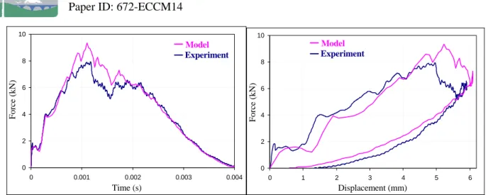
An impact test is performed at a 30 J energy corresponding in an initial velocity of 5.4 mm/s with the used 2.05 kg-mass impactor. The curves of the impact force versus the time and the impactor displacement are drawn respectively figures 6a and 6b. The interfaces delaminations, obtained by ultrasonic investigation on impacted side, are reported figure 9. Thanks to the relatively simple stacking sequence used in this study, it is easy to identify each delaminated interface on this C-Scan. It can be noted on this figure the interfaces are numbered from non-impacted side toward impacted side. The permanent indentation has been equally measured 48 h after impact and evaluated to 0.7 mm. This permanent indentation is typical of BVID which is classically taken equal to about 0.6 mm without humidity aging ([8-9]).
2.2 Permanent indentation investigation
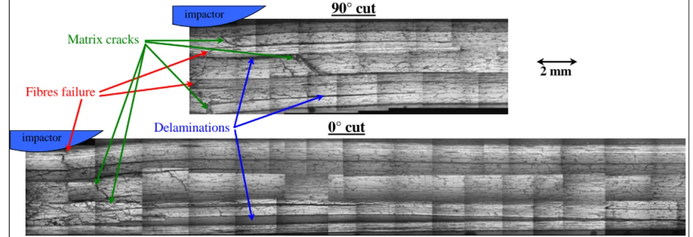
In order to study the phenomenon of permanent indentation after impact and the impact damages morphology, 2 different post mortem cuts and microscopic photos were done (fig. 1). These micrographs show clearly the impact damages like matrix cracks, delaminations or fibres failures. In particular, permanent openings of these cracks are clearly observed. For example a very large delamination opening of the first interface non-impacted side of about 0.5 mm is observed. These observations show that the permanent openings of these cracks are
due to the presence of debris that get infiltrated in the different cracks and create a blocking system ([6]). This explanation of the permanent indentation formation is to be confirmed and should not be the alone responsible phenomenon, and other phenomena like permanent strains of resin should equally play a role. Nevertheless this phenomenon of blocking system due to impact debris of matrix cracking has been supposed preponderant in the formation of the permanent indentation. And there has been taken into account in the finite element (FE) model (cf. § 3.2) in order to simulate the permanent indentation after impact.
90° cut 0° cut 2 mm impactor impactor Matrix cracks Fibres failure Delaminations
Figure 1. Post-mortem microscopic cuts in the 0° and 90° direction
3 Numerical modelling
The proposed modelling is quickly described in this paper but more details can be found in [10].
3.1 Intralaminar damage modelling
The 2 principal damages developing inner the plies are the matrix cracks and the fibres failures. The matrix cracking is simulated thanks to interface elements, then the ply mesh consists in volumic elements with a side parallel to the fibres directions and one element in the thickness (fig. 2). These elements strips, representative of strips of fibres and resin, are jointed together with interface elements of null thickness and very high stiffness (typically 106 MPa/mm). When this interface element is safe, 2 consecutive strips are perfectly jointed, but when a matrix crack exists, the interface stiffnesses are put to zero and 2 consecutive strips are disjointed. The matrix crack is derived from a classical quadratic equation:
( )
2 1 2 2 2 ≤ + + ⎟ ⎟ ⎠ ⎞ ⎜ ⎜ ⎝ ⎛ + f lt tz lt f t tτ
τ
τ
σ
σ
(1) where σt is the transverse stress, τlt and τ tz the shear stresses in the (lt) and (tz) planes, < >+the positive value and σtf and τltf the failure stresses mentioned above. A particularity of this
modelling is to drive this matrix cracking criterion of these interface elements thanks to stresses in adjacent volumic elements and not thanks to stresses in the interface elements. This allows to avoid stress concentration in the tip of matrix cracks but imposes a discussion between the volumic elements and the interface elements.
Matrix Cracks Planes t l z Model Disjointed Strips Model Broken Interfaces Safe Interfaces Interface I1 : driven by criteria in volumic elements E1, E2 Fibres direction E 1 I1 E2
Figure 2. Ply modelling
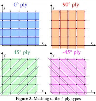
This ply modelling enables to correctly take into account the matrix cracks discontinuities observed in experiments but it obliges to build a particular and refined meshing. In fact the ply model imposes a special meshing for the ±45° plies with diamond shaped elements to allow for the coincidence between 2 consecutive plies (fig. 3).
x 0° ply y x 90° ply y x -45° ply y x 45° ply y
Figure 3. Meshing of the 4 ply types
The fibres failure is simulated with a classical strain failure criterion in the volumic elements:
(2) f
l
l
ε
ε
≤
where εl is the longitudinal strain and εlf is given table 1. When this criterion is reached, the
longitudinal stress σl and the 3 shear stresses τlt, τtz, and τlz are put to zero.
3.2 Permanent indentation modelling
In order to simulate the permanent opening of the matrix cracks observed in experiments, the interface elements of matrix cracking, which are broken, are avoid to close. Practically if the opening displacement dt in the transverse direction or the shear displacement dz in the
crack closure. Moreover the non-closure of a matrix crack can only exist for dt positive but
can exist for dz positive or negative:
(3)
(
)
(
)
(
)
(
)
(
)
(
)
⎪ ⎪ ⎪ ⎪ ⎩ ⎪⎪ ⎪ ⎪ ⎨ ⎧ ⎩ ⎨ ⎧ + = ⇒ > = ⇒ − ≤ ⇒ − ≤ ⎩ ⎨ ⎧ − = ⇒ < = ⇒ ≥ ⇒ ≥ ⎩ ⎨ ⎧ − = ⇒ < = ⇒ ≥ ⇒ ≥ ≤ ≤ ≤ 0 0 0 0 0 0 0 0 0 0 0 0 . 0 ) ( min . 0 ) ( max . 0 ) ( max d d k d d d d d d d d k d d d d d d d d k d d d d d d z tz z tz z z t z tz z tz z z t t t t t t t t τ τ τ τ τ τ σ σ τ τ τ τIn fact the d0 value represents the minimum crack opening necessary to the formation of
debris in order to create a blocking system. Moreover, as the matrix cracks direction is 45°, the d0 values in opening displacement dt and in shear displacement dz are supposed equal.
This modelling of permanent indentation is original and must be confirmed thanks to other experimental investigations. In fact the values of d0 and k have been evaluated thanks to
permanent indentation measured at 30 J-impact and prevents actually the use of this permanent indentation modelling as a predictive tool but rather as a qualitative tool.
d0 (mm) k (MPa/mm) 0.02 10000
Table 2 : Material characteristics for permanent indentation of the T700/M21 composite
These d0 and k values should be tested on other experimental tests and in particular on
different energies of impact.
3.3 Interlaminar damages modelling
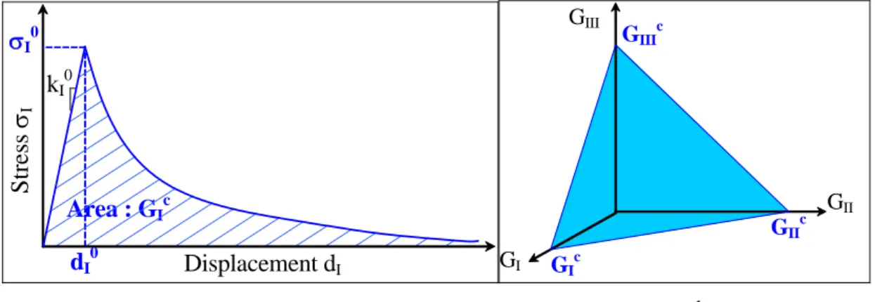
The interlaminar damages consist with delaminations between 2 consecutive plies. This damage is classically simulated thanks to interface elements of null thickness driven by the fracture mechanics ([11]). A classical softening behaviour is imposed between the stress σ and the displacement dI to allow the dissipation of the energy release rate GIc at the interface
(fig. 3a): kI 0 Displacement dI Str es s σI Area : GI c σI0 dI 0 GI GIc GII GIII GIIc GIIIc -a- -b-
Figure 3. Softening law of the stress-displacement curve (a) and linear mixed mode of fracture (b)
(4)
(
)
(
)
(
)
⎪⎩ ⎪ ⎨ ⎧ − − = ⇒ > = ⇒ ≤ ≤ ≤ ) ( exp . ) ( max . ) ( max 0 0 0 0 0 I I I I I I I t I I I I I t d d d d d k d d β σ σ τ σ τ τ τand the coefficient βI is determined to dissipate the energy release rate GIc under the
strain-stress curve. Moreover a linear mixed mode of fracture is imposed (fig. 3b): 1 = + + c III III c II II c I I G G G G G G (5)
Where GI, GII and GIII are the energy release rates respectively in mode I, II and III and GIc,
GIIc and GIIIc are the critical energy release rates respectively in mode I, II and III. The critical
energy release rates GIc and GIIc are evaluated thanks to table 1, and the critical energy release
rate in mode III is supposed equal to the one in mode I. The initial stiffnesses kI0, kII0 and kIII0
in the 3 directions are supposed very high (in fact 106 MPa/mm) and the limit stresses σI0 and
σII0 are chosen equal respectively to σtf anf τltf. Once more time, the direction III is supposed
equivalent to the direction II and σIII0 is supposed equal σII0. In fact the equality of the σI0, σII0
and σIII0 stresses with the matrix cracking stresses allows to use the same criterion for the
initiation and the propagation of the delamination.
4 Experimental validation of the modelling
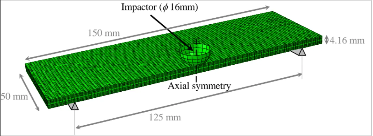
Finally, this modelling was set up in the FE software abaqus® explicit and the 30 J impact test above mentioned was simulated. The half composite plate is meshed with 1 volumic element by plies sequence of same orientation, then 7 elements in the thickness [0°2, 45°2, 90°2, -45°4,
90°2, 45°2, 0°2] with a double thickness element in the middle, and axial symmetry condition
around the z-axis is imposed (fig. 5).
150 mm 50 mm Axial symmetry 125 mm 4.16 mm Impactor (φ 16mm)
Figure 5. Finite element modelling of the plate
The curve of the impact force versus time is drawn figure 6a. A good correlation is observed between the experiment and the modelling, even if a little overestimation of the force is obtained between 1 and 2 ms. This overestimation should be due to the numerous fibre fractures observed experimentally which are not well taken into account by the modelling. The fibre failure criterion should be improved and in particular the post failure degradation. In fact, the question on the stresses to degrade after failure and on the energy release rate dissipated by the fibres failure should be studied. The curve of the impact force versus the displacement is drawn figure 6b. A good correlation is also observed with the overestimation of the force previously mentioned.
0 2 4 6 8 10 0 0.001 0.002 0.003 0.004 Time (s) Fo rce (k N) Experiment Model 0 2 4 6 8 10 0 1 2 3 4 5 6 Displacement (mm) Force (kN) Experiment Model -a- -b-
Figure 6. Impact force versus time (a) and versus displacement (b)
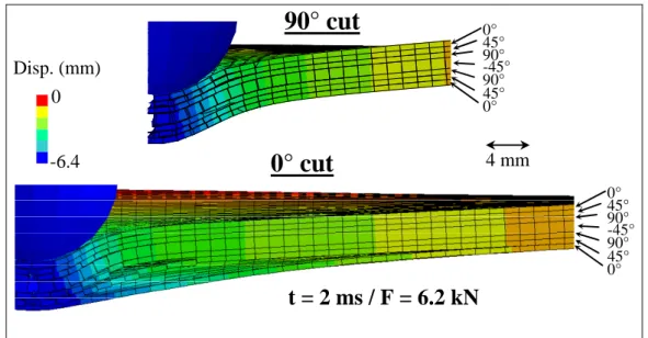
Cuts of the plate in the 0° and 90° direction at the time of 2 ms are drawn figure 7. The openings of the matrix cracks and of the delaminations are clearly observed. In particular the large opening of the first interface non-impacted side is obviously visible in the 0° cut. In the same time, this large opening is not visible in the 90° cut. This is due to the direction of the fibres. In fact the first ply, non impacted side, is directed in the 0° direction and tends to open the first interface non impacted side and to propagate it in the 0° direction. This large propagation in the 0° direction is clearly observed on the delamination picture obtained by ultrasonic investigation (fig. 9). This opening is equally observed after impact as on the experimental micrograph (fig. 1) as on the FE modelling cut (fig. 8). Indeed, when the impact force is come back to zero, a permanent displacement is still present on the FE modelling thanks to the non-closure system of matrix cracking interface elements. Nevertheless the permanent opening of the first interface non-impacted side obtained by modelling is too high compared to the experiment (fig. 1). It should be to the non-closure parameters k and d0 or
more generally to the non-closure modelling principle. Indeed the development of this modelling is still in an early stage and need to be improved.
Nevertheless the general shape of the laminate plate after impact obtained numerically (fig. 8) is in good agreement with the experimental observations (fig. 1). For example, the large opening of the first ply (non-impacted side) matrix crack located just under the impactor is clearly observed in the 90° cut, as numerically (fig. 8), as experimentally (fig. 1). It is equally the case for the important middle ply matrix crack. This matrix crack is oriented at 45° in the experimental observations (fig. 1) and should be due to shear stress particularly important in the middle of the thickness. Of course this 45° direction can not be taken into account by the modelling but this matrix cracking is numerically found and its opening after impact is equally simulated (fig. 8).
t = 2 ms / F = 6.2 kN
0 -6.4 Disp. (mm) 0° 45° 90°-45° 45° 90° 0° 4 mm90° cut
0° cut
0° 45° 90° -45° 45° 90° 0°Figure 7. Cuts of the FE modelling at 2 ms-time in the 0° and 90° directions
t = 4 ms / F = 0 kN
0 -6.4 Disp. (mm) 0° 45° 90° -45° 45° 90° 0° 4 mm90° cut
0° cut
0° 45° 90° -45° 45° 90° 0°Figure 8. Cuts of the FE modelling after impact at 4 ms-time in the 0° and 90° directions
The value of the permanent indentation given by simulation of 0.6 mm impacted side is in good agreement with the measured value of 0.7 mm. We want to point out that this comparison should be considered with caution because of the evaluation of the k and d0
parameters was performed thanks to the experimental permanent indentation. Then this modelling of post impact deformation should be considered as a qualitative tool rather as a quantitative tool. But it could be user to better understand the permanent indentation formation which is a dominating parameter for the impact damage tolerance.
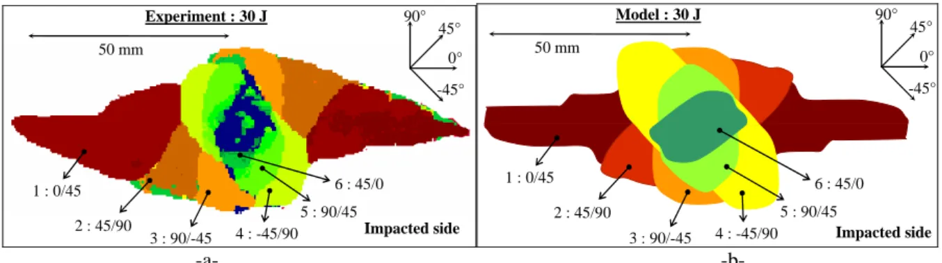
The delaminated interface areas obtained after the impact test by experiment and by calculation are drawn figure 9. The comparison between these 2 delamination pictures is good and confirms the proposed modelling allows to account for experimental scenario of impact damage. In particular the delamination propagation is always driven by the direction of the lower ply, which is well taken into account by the modelling. Moreover, contrary to the permanent indentation modelling, no one material parameter has been identified thanks to impact test. This allows to confirm the good behaviour of the proposed modelling and to confirm its ability to foresee the impact damages.
50 mm 0° 90° 45° -45° 1 : 0/45 2 : 45/90 3 : 90/-45 4 : -45/90 5 : 90/45 6 : 45/0 Experiment : 30 J Impacted side 50 mm 0° 90° 45° -45° 1 : 0/45 2 : 45/90 3 : 90/-45 4 : -45/90 5 : 90/45 6 : 45/0 Model : 30 J Impacted side -a- -b-
Figure 9. Experimental (a) and modelled (b) delaminations 5 Conclusion
An impact damage has been set up to simulate the different damage types forming during an impact on composite panel. The 3 principal damages, which are matrix cracks, interfaces delamination and fibres failure, are well taken into account by the proposed modelling thanks to interface elements. In particular the interaction between the matrix cracking damage and the delamination, which is a crucial point for the impact damages, is directly simulated without addition of interaction parameter. The modelling parameters are directly identified thanks to classical material tests.
The modelling allows equally to simulate the permanent indentation which is a dominating parameter to certify a composite structure in damage tolerance concept. Unfortunately this part of this modelling imposes the introduction of supplementary parameters which are not until now evaluated thanks to classical material tests. But this inconvenience could be solved in the future and more work is still necessary to improve this modelling. This permanent indentation modelling should be considered as a qualitative tool rather as a quantitative tool. Nevertheless this modelling idea is totally original and could help to better understand the formation of permanent indentation which is until now a not well known phenomenon.
Afterwards this modelling will be used as an initial condition to simulate a test of compression after impact in order to evaluate the residual strength in compression due to impact damages. In effect, in order to completely optimize the design of composite structure in damage tolerance, it is necessary to simulate each phase of the problem: the damages development during impact, the permanent indentation creation during impact and the damages propagation and the final failure during compression after impact.
References
[1] Allix O., Blanchard L.: Mesomodelling of delamination: towards industrial applications. Composites Science and Technology, 66, 731-44 (2006)
[2] Choi H. Y., Chang F. K. : A model for predicting damage in graphite / expoxy laminated composites resulting from low-velocity point impact. Journal of Composite Materials, 26 (14), 2134-69 (1992)
[3] Li S., Reid S. R., Zou Z.: Modelling damage of multiple delaminations and transverse matrix cracking in laminated composites due to low velocity lateral impact. Composites Science and Technology, 66, 827-36 (2006)
[4] Finn S. R., Springer G. S.: Delaminations in composite plates under transverse static or impact loads. Composite Structures, 23, 177-204 (1993)
[5] De Moura M. F., Gonçalves S. F.: Modelling the interaction between matrix cracking and delamination in carbon-epoxy laminates under low velocity impact. Composites Science and Technology, 64, 1021-7 (2004)
[6] ABI ABDALLAH E., BOUVET C., RIVALLANT S., BROLL B., BARRAU J. J.: Experimental analysis of damage creation and permanent indentation on highly oriented plates. Composites Science and Technology, 69 (7-8), 1238-45 (2009)
[7] PROMBUT P. : Caractérisation de la propagation de délaminage des stratifiés composites multidirectionnels. Thèse de doctorat, université de Toulouse (2007)
[8] ALDERLIESTEN R. C.: Damage tolerance of bonded aircraft structures. International Journal of Fatigue, 31 (6), 1024-30 (2008)
[9] TROPIS A., THOMAS M., BOUNIE J. L., LAFON P.: Certification of the composite outer wing of the ATR72. Journal of Aerospace Engineering, Proceedings of the Institution of Mechanical Engineers Part G, 209, 327-39 (1994)
[10] BOUVET C., CASTANIE B., BIZEUL M., BARRAU J. J.: Low velocity impact modelling in laminate composite panels with discrete interface elements. International Journal of Solids and Structures, 46 (14-15), 2809-21 (2009)
[11] MI Y., CRISFIELD M.A., DAVIES G. A. O.: Progressive delamination using interface elements. Journal of Composite Materials, 32 (14), 1246-72 (1998)