HAL Id: hal-01760348
https://hal.archives-ouvertes.fr/hal-01760348
Submitted on 12 Jul 2019HAL is a multi-disciplinary open access archive for the deposit and dissemination of sci-entific research documents, whether they are pub-lished or not. The documents may come from teaching and research institutions in France or abroad, or from public or private research centers.
L’archive ouverte pluridisciplinaire HAL, est destinée au dépôt et à la diffusion de documents scientifiques de niveau recherche, publiés ou non, émanant des établissements d’enseignement et de recherche français ou étrangers, des laboratoires publics ou privés.
With Floating Ground Plane
Ines Rouissi, Jean Marie Floc’h, Hatem Rmili, Hichem Trabelsi
To cite this version:
Ines Rouissi, Jean Marie Floc’h, Hatem Rmili, Hichem Trabelsi. Design of Frequency Reconfigurable PIFA Antenna With Floating Ground Plane. Indian Journal of Science and Technology, Indian Society for Education and Environment, 2018, 11 (5), pp.1-11. �10.17485/ijst/2018/v11i5/118872�. �hal-01760348�
Design of Frequency Reconfigurable PIFA Antenna
with Floating Ground Plane
Ines Rouissi
1*, Jean-Marie Floc’h
2, Hatem Rmili
3and Hichem Trabelsi
11URCRFS, Faculty of Sciences of Tunis, University of Tunis El Manar, 1002 Tunis, Tunisia;
ines.rouissi@gmail.com, hichem.trabelsi@fst.rnu.tn
2IETR, INSA Rennes, 20 avenue Buttes de coësmes, 35043 Rennes, France; jean-marie.floch@insa-rennes 3King Abdulaziz University, Faculty of Engineering and Computer Engineering Department, P.O. Box 80204, Jeddah
21589, Saudi Arabia; hmrmili@kau.edu.sa
*Author for correspondence
Abstract
Objectives: The rapid evolution of wireless communications systems open the field to frequencncy reconfigurable antenna. In this paper, we propose to study and design a PIFA antenna with frequency agility characteristic. Methods/Analysis: The reference antenna resonate at F = 1000 MHz. It consist of a PIFA design printed on the top side and the grounded PCB in the back one. To obtain a low profile and have a multiband behavior, a floating ground plane was printed in back side of the antenna coupled with the radiating PIFA element. A two resonances frequencies can be obtained. To electronically reconfigure the antenna in a determined band and acquiring a large tuning range, a varactor diode was embedded in the corner of the radiating element. Findings: When adding a floating ground plane, a two resonances frequencies can be obtained at 920 and 2800 MHz with better than -10 dB impedance match. To obtain three resonance frequencies with wide tuning ranges, we apply a reverse voltage V on the varactor diode. Frequencies can be shifted from 650 to 2457 MHz covenring GSM850/1900/UMTS/LTE700/LTE2300 and ISM band. The reference and the active antennas were designed and described. Good agreement between simulations and measurement results. Application/Improvements: This work show that tunable PIFA antenna are promising candidate for handheld portable.
Keywords: Floating Ground Plane, Frequency Agility, Large Tuning Range, PIFA, Reconfigurable Antenna, Varactor Diode
1. Introduction
The increase demand for portable devices with wireless connectivity across a broad frequency spectrum is the major challenge facing RF designers, because they have to manage the interconnection of both standards such as GSM, UMTS, WiMAX, Bluetooth, LTE,… Covering several frequency bands simultaneously with a single antenna may be a very demanding task. To deal with this problem, frequency-reconfigurable antennas represent important research and development axes for intro-ducing elasticity on the antenna characteristics1,2. The
advantage given by these kinds of antennas is to make the wireless telecommunication systems more flexiblefor sev-eral applications3–5.
The Planar Inverted F-antenna (PIFA) is very popular in the portable terminals industry because of its compact-ness, ease integration and their low manufacturing cost6,7.
However, it exhibits narrow bandwidth. Thereby, design-ing PIFA antenna with the ability to electrically control its resonances frequencies is strongly desired. Several researches has been conducted for this purpose. In8, the
antenna occupies a size of 30 × 10 mm². The antenna use only one PIN diode to cover GSM850/900/1800/1900/ UMTS/LTE2300/LTE2500 mobile handset. In9, the
reported antenna occupies size of 27 × 10 mm². The antenna can be resonated both in the PIFA and loop mode by adjusting the ON/OFF state of the PIN diode. Nevertheless, the antenna can not cover the GSM 850
band. M. N. M. Kehn and O. Q. Teruel proposed a reconfigurable microstrip patch antenna. The frequency agility was achieved using a varactor diode10. Based on the
above discussion, we present a novel multiband tunable PIFA antenna covering GSM850/1900/UMTS/LTE700/ LTE2300 and ISM band. A floating ground plane was printed under the radiating element in order to minia-turized and obtain a low profile antenna. To dynamically control the resonance frequencies, a varactor diode was inserted in the corner of the antenna. The designed antenna not only occupies a significantly smaller size 50 × 13.5 mm² but also seems to be a simpler structure than the mobile handset antenna mentioned above.
2. Reference PIFA Antenna
2.1 Antenna Design
The dimensions of the proposed antenna is presented inure 1. The antenna is printed on 70 × 150 × 1.6 mm3
FR4 substrate with Ԑr = 4.4. The radiating element is printed on the upper side and the grounded PCB in the
back side. The ground plane (70 × 132 mm²) is considered to be longer than the radiating element with the aim to reflect the radiated power in the front direction (θ = 0°). A SMA connector use to feed the reference antenna and a shorting plate is used to short-circuit the top patch to ground plane.
2.2 Results and Discussion
The passive PIFA antenna was studied and simulated using the ANSYS ANSOFT HFSS.V15. The simulation reflexion coefficient S11 exhibits one resonant frequency F1 = 1 GHz as it can be shown in Figures 1 and 2.
The 3D simulated radiation pattern for F1 = 1 GHz is
displayed in Figure 3. The antenna have a maximum radi-ation towards the positive Z-direction and a maximum gain of 3.07 dB. This result is due to the presence of the reflector plane which reduces the back radiation.
The surface current vectors distribution in the antenna at 1 GHz is illustrated in Figure 4. We can notice that these currents are especially localized in the close part to the feed line.
Figure 2. Simulated return loss S11 of the reference PIFA antenna.
3. PIFA Antenna with Floating
Ground Plane
3.1 Antenna Design
To miniaturized and obtain a low profile antenna11, a
floating ground plane was added on the back side below
the PIFA. It is able to changing the effective permittivity of the antenna and increase the electrical length of the radiating section. Thus, the overall size of the antenna is well reduced. The fabricated antenna is exhibited in Figure 5.
Figure 4. Surface current distribution at F1 = 1 GHz.
3.2 Results and Discussion
Figure 6 presents the return loss of the proposed bi-band PIFA antenna.
According to Figure 6, we can note that the PIFA antenna is characterized by a high simulated frequency at 2.8 GHz in addition to the resonance frequency, 0.92 GHz of reference PIFA antenna. The measured carried out show that the obtained antenna behaves as predicted. Indeed, measured resonances frequencies are 0.95 and 2.88 GHz. This result is due to the fact that the addition of floating ground plane under the radiating element in the aim to increase the coupling between them, generate a second resonance frequency.
To analyse the origin of these resoances frequencies, we have studied the current distribution for the pro-totype. Figure 7 illustrates simulated surface currents for the antennas at their resonance frequencies. The current is concentrated in the center of the radiating element and in the near zone of the supply line for the low frequency F1 = 0.92 GHz. For the high frequency F2 = 2.8 GHz, the current flow propagates at the end of the radiating element with a weak current at the cen-ter of the antenna. Which explains the importance role of adding a floating ground plane. The simulated and measured radiation patters presented in Figures 8 and 9, respectively. They confirm the radiation behavior of the
structure described in Figure 7. Maximum simulated realized gain are 3.17 at 0.92 and 3.39 dBi at 2.8 GHz. Measured obtained gain are 2.28 at 0.95 and 2.44 dBi at 2.88 GHz.
4. Frequency Reconfigurable PIFA
Antenna
4.1 Antenna Design
To dynamically control the resonance frequencies in a large tuning range, we considered integrated a varactor diode; BB833 from Infineon. It was loaded in the corner of the radiating element and the floating ground plane as it can be shown in Figure 10. The location of varac-tor diode is determined following a study of the surface currents distribution. In fact, we notice that the embed-ding of the diode at the zone where the concentrations of surface currents are high is irrelevant. In fact, in order to redirect the current flow, the diode must be placed in the region where the distribution of the surface currents is of low concentration. This location facilitates the estab-lishment of new paths of the flux of surface currents. The agility characteristic was obtained by appliying a variable reverse voltage V on the varactor diode. Hence, we change the capacitor values which affects the electric length of the PIFA leading to a continuous frequencies shift.
(a)
(b)
Figure 7. Simulated surface current distribution of the proposed antenna at: (a) 0.92 GHz and (b) 2.8 G.
(a) (b)
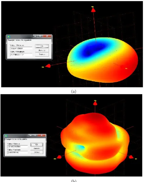
(a)
(b)
Figure 9. Measured 3D radiation pattern at: (a) 0.95 GHz and (b) 2.88 GHz.
4.2 Results and Discussion
Figure 11 presents the S-parameter measurements when the bias diode is changed (0-17 V). In fact, the loading of the varactor diode generates a new frequency F2, in the center of of the exsitante resonances frequencies, that shift to lower frequencies when decreasing the reverse bias voltage (increase of the capacitor values). The first frequency F1 is the reference antenna resonance fre-quency. By controlling the bias voltage V, F1 can be moved from 896 to 650 MHz. The third frequency F3 (reference antenna resonances frequency), shifted to lower frequen-cies. A wide tuning frequencies range of 2457 to 1502 MHz was obtained. For F2, a tuning range of 1379 to 954 MHz was achieved. Table 1 summarized the measured resonant frequencies of the proposed antenna. For rai-son of clarity, we presented the measured and simulated reflection coefficient for reverse bias V = 4 v (C = 4 pF) in Figure 12. A good agreement can be noticed between
both simulated and measurement results. The differences between simulated and measured in the higher frequen-cies can be explained by the fact that we only consider the varactor diode model like a capacitor without taking into account the losses of the diode.
The surface current vectors distribution in the antenna at 0.82 and 1.18 GHz are illustrated in Figure 13 respec-tively. As it can shown, at the frequency 0.82 GHz the path of the surface current is alike that of the unloaded antenna for the first frequency. At the second frequency (1.18 GHz), the streams are redirected to the diode with a maximum current located in the corner.
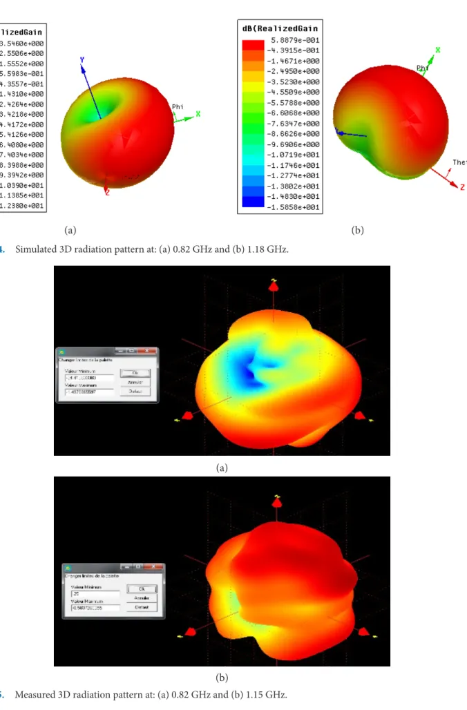
The simulated and measured 3D radiation pattern for V = 4 V are plotted in Figures 14 and 15 respectively. The proposed antenna presents stable radiation properties and they confirm the radiation behavior of the structure described in Figure 13 with maximum simulation gain 3.54 at 820 and 0.58 dBi at 1180 MHz. The obtained mea-sured gain are -1.49 at 820 and -0.58 dBi at 1150 MHz.
Figure 12. Simulated and measured return loss S11 for V = 4 V (C = 4 pF).
Figure 13. Simulated surface current of the PIFA antenna for V = 4 V at: (a) 0.82 GHz and (b) 1.18 GHz. (a)
(a) (b)
Figure 14. Simulated 3D radiation pattern at: (a) 0.82 GHz and (b) 1.18 GHz.
(a)
(b)
Table 1. Measured resonant frequencies Voltage (V) value (pF)Capacitor F1 F2 F3 Unloaded antenna -- 954 -- 2880 17 0.9 896 1379 2457 13 1 890 1356 2400 10 1.4 880 1318 2313 8 1.8 870 1275 2217 6 2.8 840 1204 2091 4 4 820 1150 1989 2 7 740 1079 --1 9.8 700 1060 --0 ≈20 650 1039
--5. Conclusion
A tunable PIFA antenna covering 650-2457 MHz bands has been demonstrated. The antenna reference with size
70 × 132 ×1.6 mm3 resonate at 1000 MHz. A floating
ground plane was added coupled with radiating element in order to miniaturized and obtain a low profile antenna. A two resonances frequencies was obtained at 920 and 2800 MHz. To sweep the resonances frequencies in a
desired bands, one varactor diode was integrated between the radiating patch and adding floating ground plane. A large tuning frequencies range of 650-896, 1039-1379, 1989-2457 MHz was achieved. Good agreement between simulations and measurements. The goal of this work is
to show that tunable PIFA antenna are promising
candi-date for handheld portable. A lot of additional research
are planned to enhance the antenna performance to cover additional bands.
6. References
1. Nghia NT, Andrew P, Christophe F. A frequency recon-figurable dual-band low-profile monopolar antenna. IEEE Transactions on Antennas and Propagation. 2017 Jul; 65(7):3336–43. Crossref.
2. Jari-Matti H, Jari H, Ville V. Concept for frequency-recon-figurable antenna based on distributed transceivers. IEEE Antennas and Wireless Propagation Letters. 2016 Aug; 16:764–7.
3. Yasir I, George A, Abdulkareem S, Husham J, Ramzy A, Raed A, James M. Design of frequency reconfigurable mul-tiband compact antenna using two PIN diodes for WLAN/ WiMAX applications. IET Institution of Engineering and Technology Microwaves, Antennas and Propagation. 2017 Jul; 11(8):1098–105.
4. Homayoon O, Nooshin V. Frequency- and time-domain analysis of a novel UWB reconfigurable microstrip slot antenna with switchable notched bands. IET Institution of Engineering and Technology Microwaves, Antennas and Propagation. 2017 Jul; 11:1127–32.
5. Liping H, Caixia W, Xinwei C, Wenmei Z. Compact frequency-reconfigurable slot antenna for wireless appli-cations. IEEE Antennas and Wireless Propagation Letters. 2016 Mar; 11:1795–8.
6. Hoang T, Vu L, Vu V. Design of compact frequency reconfigurable planar invert-F antenna for green wire-less communications. IET Institution of Engineering and Technology Communications. 2016 Dec; 10:2567–74. 7. Byeonggwi M, Changwon J, Myun-Joo P, Byungje L.
A compact frequency-reconfigurable multiband LTE MIMO antenna for laptop applications. IEEE Antennas and Wireless Propagation Letters. 2014 Jul; 13:1389–92. Crossref.
8. Sungwoo L,Youngje S. Reconfigurable PIFA with a para-sitic strip line for a hepta-band WWAN/LTE mobile handset. IET Institution of Engineering and Technology Microwaves, Antennas and Propagation. 2015; 9:108–17. 9. Youngje S. Multi-band reconfigurable antenna for mobile
handset applications. IET Institution of Engineering and Technology Microwaves, Antennas and Propagation. 2014; 8: 864–71.
10. Malcolm N, Oscar Q, Eva R. Reconfigurable loaded planar inverted-F antenna using varactor diodes. IEEE Antennas and Wireless Propagation Letters. 2011 May; 10:466–8. Crossref.
11. Rouissi I, Floc’h JM and Trabelsi H. Design of frequency reconfigurable multiband meander antenna using varactor diode for wireless communication. International Journal of Advanced Computer Science and Applications. 2017 Mar; 8(3):159–64. Crossref.