Proceedings of the ASME 2013 32nd International Conference on Ocean, Offshore and Arctic Engineering OMAE2013 June 9-14, 2013, Nantes, France
OMAE2013 - 11067
A SIMPLIFIED PROCEDURE TO ASSESS THE STRENGTH OF A SHIP IMPACTING
A LOCK MITERED GATE
Loïc Buldgen
FRIA PhD Student, University of Liège ANAST Department, Liège, Belgium
Hervé Le Sourne
Professor, Institut Catholique d’Arts et Métiers Mechanical Engineering Department, Nantes, France
Philippe Rigo
Professor, University of Liège ANAST Department, Liège, Belgium
ABSTRACT
This paper presents a simplified procedure allowing for a rapid prediction of the strength of a lock mitered gate submitted to a ship impact. In this article, the force opposed to the penetration of the vessel is derived by supposing that the bow is perfectly rigid, so the total initial kinetic energy has to be entirely transformed through an internal dissipation. For a given penetration of the striking vessel, an analytical procedure is followed in order to estimate the amount of energy dissipated by local and global deformations of the impacted structure. An equivalent quasi-static force is then derived. A comparison is made with a finite elements simulation in order to test the analytical procedure.
1 INTRODUCTION
Locks are undoubtedly essential and common structures on inland waterways. Although some recent efforts have been made to improve the navigation near such installations, the gates are often impacted by ships travelling too fast. Most of the time, these collisions lead to some minor damages such as a loss of watertightness. However, as the fluvial traffic is growing, it is to fear that the frequency of these accidents is going to follow the same trend. Moreover, as ships are also getting larger, collisions are likely to have much more severe consequences.
For these reasons, it seems reasonable to think that ship impact on lock gates will be an important matter of concerns for engineers in a near future. It is therefore necessary to provide them with some efficient tools to check if a new or an existing lock gate is able to withstand a collision. Of course, finite elements simulations may be performed, but they are not time-effective at the pre-design stage of a structure, when several
collision scenarios must be analyzed. Therefore, in this paper, we present a simplified methodology that can be used to quickly estimate the resistance of a lock mitered gate.
The philosophy is the same than the one detailed (amongst others) by Ueda [1] and Lützen [2] for ship-ship collisions or by Simonsen [3] for ship grounding on rocks. The idea is to assess the crashworthiness with help of simplified analytical developments. Such an approach has already been applied to plane gates by Le Sourne [4] and Buldgen [5] and it is our aim to extend it to classical lock mitered gates.
2 HYPOTHESES AND OVERVIEW OF THE PROBLEM The developments performed in this paper are based on several hypotheses concerning:
-The structure of the impacted gate;
-The behavior of the material constituting the gate; -The shape of the striking vessel.
The theory presented in this article is strictly limited by the restrictions detailed hereafter. However, the assumptions are made so as to cover the main practical cases.
2.1 Hypotheses on the gate structure
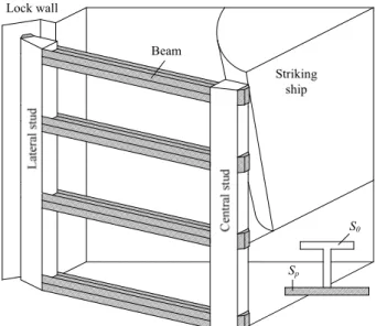
Figure 1 represents a top view showing the main geometrical and structural properties of the gates considered in this paper. A leaf is assumed to be made of a plating reinforced by some frames (vertical stiffeners) and girders (horizontal stiffeners).
Contacts with the lock walls and the second leaf are respectively provided by the lateral and central blocks. These one are assumed to be perfectly rigid and located at the same vertical level than the girders, as it can be seen on Figure 2.
This figure also shows that the stiffened structure formed by the plating, the frames and the girders is supported by two vertical studs (a central and a lateral one).
L o ck w al l
Figure 1. Top view of the left leaf of a mitered gate.
L
o
c
k
w
a
ll
F
ra
m
e
C
en
tr
al
s
tu
d
L
at
er
al
s
tu
d
Figure 2. Plan view of the left leaf of a mitered gate. 2.2 Hypotheses on the material behavior
In order to derive a closed form solution of the impact resistance, the material is supposed to first exhibit a linear elastic behavior defined by its Young’s modulus E. Once the maximal elastic deformation ε0 is reached, the material then
exhibits a plastic behavior characterized by a constant flow stress σ0 = Eε0, which implies that the strain hardening is not
taken into account. In the developed analytical model, the stress-strain rate sensitivity is also neglected. Such hypotheses are however conservative.
It is worth noting that rupture is not taken into account in the present paper. The first reason to do so is that tensile tearing occurring in the plating would lead to a loss of watertightness, which has to be avoided to maintain the integrity of the lock.
Therefore, the post-rupture behavior of the gate is not a prior matter of investigation. Another reason for not dealing with failure comes from the difficulty to simulate properly tensile tearing using finite elements. As a consequence, the material considered in this paper is not able to simulate rupture.
2.3 Hypotheses on the striking vessel
The mass and initial velocity of the striking ship are respectively denoted by M0 and V. In the present methodology,
the vessel is assumed to be perfectly rigid, so that no deformation is likely to affect the impacting bow. In particular, this conservative hypothesis implies that the initial kinetic energy M0V2/2 has to be entirely dissipated during the
deformation of the gate.
Geometrically, the striking vessel is characterized by five different parameters shown on Figure 3:
-the bow is assumed to be a parabola with radii p and q; -the stem and side angles are respectively denoted by ψ and ϕ; -the height between the lower and uppermost decks is hb.
Finally, regarding the collision scenario, the vessel is first assumed to always move in a direction parallel to the lock walls, as depicted on Figure 1. This hypothesis seems to be reasonable, as very large ships always occupy the all space of the lock chamber. The impact is then supposed to be symmetric, which means that the vessel is colliding the gate at the junction between the two leafs (Figure 1). As a consequence, off-centered impacts are not covered here.
Figure 3. Geometrical description of the striking bow. 3 ANALYTICAL METHODOLOGY
The analytical derivation of the collision resistance is based on the fundamental assumption that the collision energy is entirely dissipated by the gate at two different levels:
-At the beginning of the impact, i.e. for small values of the penetration δ of the striking vessel, the resistance is mainly provided by some local damage affecting the gate in a localized area. During this so-called local deforming mode, deformations are confined into a region surrounding the impact point, while the remaining parts of the gate are unaffected.
-However, when the penetration becomes larger, displacements may not be kept in a closed space anymore. The entire gate is then affected by an overall bending motion, which characterizes a global deforming mode.
1
2
δ
δ
tP
P
lP
gFigure 4. Transition between local (1) and global (2)
deforming modes.
For the local and global deforming modes, it is our purpose to estimate the associated local and global resistances, respectively denoted by Pl and Pg. Both of them are analytically
derived for each value of the current penetration δ. The transition between the local and global behavior is then assumed to happen for a particular value δt of the indentation
(Figure 4). When this indentation is reached, it becomes easier for the ship to progress by imposing an overall bending movement (phase 2 on Figure 4) of the gate than by producing local damages (phase 1 on Figure 4).
The most critical part for estimating the collision resistance P is to provide realistic laws characterizing the evolution of Pl
and Pg with δ. Some details concerning the analytical derivation
of such laws are presented in the following sections. 4 LOCAL DEFORMING MODE
The resistance in the local deforming mode is evaluated by assuming that the gate is an assembly of N large structural entities called “super-elements”. Each super-element i is characterized by a relation between the penetration δ of the striking vessel and its individual resistance Pi. In addition, the
two following important assumptions are made:
-As long as there is no geometrical contact between the striking bow and a super-element, this one remains inactive, and so we have Pi = 0.
-Each super-element is totally decoupled from the others. This means that deformations taking place in one super-element do not have any geometrical or structural effect on the others.
As a consequence, the total crushing force Pl opposed in the
local mode for a given value of δ is simply obtained by summing up the contributions Pi provided by each individual
super-element i. In other words, Pl is written as:
∑
= = N i i l P P 1 ) ( ) (δ δ (1)The relation between Pi and δ is analytically derived by
applying the upper-bound theorem. To do so, the first step is to define realistically the displacements affecting a super-element under an impact. Then, by calculating the components of the Green-Lagrange deformation tensor, the internal energy Ei,
dissipated for a given indentation, is obtained. The virtual velocities theorem (see Jones [6] for additional information about the virtual velocities principle) finally leads to the sought resistance:
i
i E
P ⋅δ&= & (2)
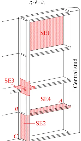
Figure 5. Representation of the four different types of
super-elements (only a portion of the gate is shown).
In order to model entirely the structure of the gate, at least four different types of super-elements are required (Figure 5): -Super-element 1 (SE1) is used to model the behavior of
plating components submitted to an out-of-plane impact. This super-element is vertically delimited by two frames and horizontally bounded by two girders.
-Super-element 2 (SE2) is used to model collided frames. A SE2 is delimited by two girders. For example, on Figure 5, the SE2 is bounded at points B and C. For such elements, it is
worth noting that the collision may not appear on one of the supports. In other words, a SE2 is always impacted somewhere between B and C, but not in B or C (otherwise it has to be treated as a SE4).
-Super-element 3 (SE3) is used to simulate the crushing of intersections between frames and girders when they are impacted.
Super-element 4 (SE4) represents girders or frames that are impacted immediately on one of their support. As the collision happens at the middle of the gate (near the central stud), it is clear that all girders have to be modeled with a SE4 (as an example, on Figure 5, the SE4 shows a girder that is activated when the bow reaches point A). A SE4 may also be used to simulate frames when they are impacted on one of their support points (B or C).
4.1 Super-element 1
SE1 is modeled as a plate simply supported on two frames and two girders. During an impact, no displacement is assumed to appear along an edge, as long as no geometrical contact with the striking bow has been established. Such an element has already been extensively studied by Zhang [7] or Buldgen [8] for example. Therefore, we will not present all the detailed mathematical developments leading to the evaluation of the resisting force. On the contrary, we will rather focus on giving a clear explanation of the hypotheses that were used to get the final formulae.
b2
b1
b2
b1
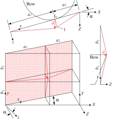
Figure 6. Displacements field for SE1.
In order to derive the individual local resistance provided by the present element, it is first necessary to define a
kinematically admissible displacement field. To do so, let’s first introduce (see Figure 6):
-A local coordinate frame (x,y,z), oriented in a such way that x and y are located in the initial plane of the plate. The axis z is then defined perpendicularly to (x,y).
-A global coordinate frame (X,Y,Z), where the plane (Y,Z) is parallel to the lock walls and the axis X is defined perpendicularly.
If we denote the mitered angle by α, it is obvious from Figure 6 that the axes (x,y,z) are simply obtained through an α-counterclockwise rotation of (X,Y,Z). Remember that the striking ship is following the orientation of the lock walls, so that the vessel is travelling along the Z axis (δ // Z) as depicted on Figure 6.
As mentioned here above, the super-element is activated as soon as a geometrical contact is established with the ship. In the present case, this condition is achieved when the bow is tangent to the initial plane of the plate. On Figure 6, the first contact point is denoted by I0. However, as the ship is moving forwards,
I0 does not follow the penetration direction Z. We assume here
that the impact only results in a displacements field w(x,y) perpendicular to the plane of the gate. In other words, w(x,y) is parallel to the z axis. As a consequence, for a given value of δ, the current position of I0 is point I on Figure 6, and we have:
x I I a a I I ⊥ + = 0 2 2 0 sin cos α δ α δ (3) Each point (x,y) initially located in the plane of the plate is submitted to the same type of motion as I0.Consequently, as the
ship is only following the Z axis, the material is forced to plastically flow over the striking bow, which may result in a frictional dissipation. However, the quantity of energy involved in this phenomenon is neglected and we admit here that there is only an internal dissipation through the straining produced by the deflection w(x,y). If we divide the plate into four different areas:
[
] [
]
[
] [
]
[
] [
]
[
1 1 2] [
1 1 2]
4 1 2 1 1 3 2 1 1 1 2 1 1 1 sin ) , ( : 0 sin ) , ( : sin 0 ) , ( : 0 sin 0 ) , ( : b b b a a a y x A b a a a y x A b b b a y x A b a y x A + × + − ∈ × + − ∈ + × − ∈ × − ∈ α δ α δ α δ α δ (4)it is possible to define the displacements field simply through a linear interpolation on each surface. For example, considering A1, we have: α δ α δsin cos ) , ( 1 1 b y a x y x w − = (5)
and the same can be done for the three remaining regions A2, A3,
A4 to get a complete definition of w(x,y). Then, assuming a plan
strain state, the Green-Lagrange formulae may be used to get the strain rate tensor. Following the same procedure than the one described in [7] or [8], it is possible to derive the internal energy rates dE1, dE2, dE3, dE4 for the regions A1, A2, A3, A4.
Applying the virtual velocities principle, we finally get the individual resistance Pi opposed by this super-element during
the impact: 4 3 2 1 dE dE dE dE d Pi δ = + + + (6)
where dE1, dE2, dE3, dE4are given in Annex A.
4.2 Super-element 2
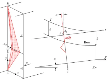
SE2 is modeled as a vertical plate simply supported on three edges. The fourth edge is free and impacted by the vessel bow (see Figure 7). The super-element is activated as soon as the bow reaches point A0 defined on Figure 7, i.e. when the
penetration is equal to δ0. It is worth noting that the frame is
located in the plane x = 0 making an angle α with the axis Z followed by the striking ship (Figure 7). As a consequence, the current indentation characterizing a SE2 is a function a(δ) which may be obtained by calculating the intersection between the parabolic curve Γ of the bow with the plane x = 0 of the frame. As an approximation, one can consider that:
(
δ δ)
αδ) cos
( ≈ − 0
a (7)
which seems to be reasonable because α is quite small (20° typically). z y x α x z X Z α δ δ δ0 a(δ) Γ Bow a(δ ) A0 A0 B C b1 b2
Figure 7. Geometrical description and displacements field
of a SE2.
For increasing values of a(δ), the deformation pattern of a SE2 is depicted on Figures 7 and 8. The plate is crushed through a folding process that implies four triangular regions denoted by ACE, ACD, BAE and CED. These ones are in fact rotating around plastic hinges designated by AC, CE, CD, AB, EB and BD, which implies both bending and membrane effects.
Such folding processes have already been studied by Zhang [7], Hong [9] or Simonsen [10], but not for inclined elements. The only difference is coming from the need to consider the local indentation as being a(δ) and not simply δ. In this paper, we will therefore not go through a detailed calculation of the
individual resistance Pi provided by a SE2 (some additional
information is given in Annex B).
Figure 8. Detailed description of the folding process. The analytical derivation of Pi is still based on the virtual
velocities principle. Here, bending and membrane energy rates have to be calculated. The bending dissipation is assumed to remain confined in the plastic hinges listed above. For each line, the rotation angle is denoted by θ and it may be shown (Annex B) that the bending energy rate is given by:
(
)
(
δ)
δ δ σ d a H a H b b t dEb p ∂ ∂ − − + = 2 2 1 2 0 2 ) ( 1 1 2 (8)where σ0 is the flow stress and tp is the frame thickness. The
membrane contribution is coming from the necessity to respect the compatibility along the deforming line AED (Figure 8). The motion is indeed impossible without any stretching of the fibers along the y axis. As a consequence, a part of the internal energy is also released through this mechanism and it can be shown (Annex B) that the membrane energy rate writes:
δ δ δ δ σ a d b a b a H t dEm p ∂ ∂ + = 2 1 0 ) ( ) ( 3 2 (9) Finally, applying the virtual velocities principle leads to the sought resistance:
m b
ida dE dE
P = + (10)
where dEb and dEm are given by (8) and (9). In equation (9), it
is worth noting that H is a parameter found by minimizing the mean crushing resistance over one fold (Annex B).
4.3 Super-element 3
SE3 is considered as an assembly of different portions of frames and girders resulting in T-, L- or X-shaped elements. A cruciform profile is represented on Figure 9. As for SE2, it is still to be noted that the local indentation is also a function a(δ) of the total penetration δ.
During the collision, these components are crushed by folding. The right part of Figure 9 shows how an isolated wing is deforming; different mechanisms are involved:
-The two triangles BCE and CED rotate around the three plastic hinges EB, EC and ED. The bending energy rate associated to this motion is denoted by dEb.
-As point C is assumed to be moving in a direction parallel to the x axis only (no displacement along y), all the fibers oriented along y have to be stretched, otherwise the compatibility along the line BCD will not be respected. The membrane energy rate associated to these elongations is denoted by dEm.
-Finally, when the line A0B0 moves in its current position AB,
this implies a compression of the fibers oriented along the z axis. The energy dissipated during this compression is noted dEc.
The mechanism exposed here above needs two different parameters to be entirely defined. The first one is the height of one fold H, while the second one is the height of one wing. If we assumed this latter to be proportional to H, it can be said that the extension of a wing is kH. As it was already mentioned for SE2, these parameters may be fixed by minimizing the mean crushing resistance calculated over one fold. This has already been done by Amdahl [11] who evaluated the individual crushing resistance Pi by the following formula:
+ + + = ⇔ + + = k k k H t P dE dE dE da P p i c m b i 1 4 1 arcsin 4 1 3 2 2 0 σ (11)
with k = 0.5733. So far, the optimal value of H remains unknown but will be fixed later on in the next section devoted to SE4. a(δ) y z x kH H y B D z A0 A C F E B0
Figure 9. Folding mechanism of a SE3. 4.4 Super-element 4
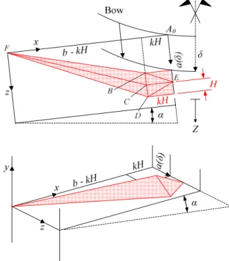
As the collision is supposed to take place at the middle of the gate, it is obvious that a girder is firstly impacted on one of its supports. Figure 10 shows both a top and a 3D view of the deformation pattern characterizing a girder whose support
which is displaced by a quantity a(δ). The first contact point with the striking bow is denoted by A0.
It is clear that the region of extension kH located near A0 is
in fact a SE3. The remaining part of the girder has an extension b - kH and corresponds to the SE4 under consideration. This one is made of two triangles BCF and CDF (Figure 10) rotating around three plastic hinges FB, FC and FD, which implies a bending energy dissipation denoted by dEb.
In order to provide a perfect compatibility between a SE3 and a SE4, the two triangles BCF and CDF have to present the same height H than the one characterizing a SE3. Moreover, points B, C and D are required to keep in the plan x = b - kH (Figure 10) as this condition was also expressed for a SE3. For increasing values of a(δ), this implies an axial stretching of all the fibers oriented along the x axis. The associated membrane energy rate is denoted by dEm.
Figure 10. Folding mechanism for a SE4.
The individual resistance Pi of a SE4 comes from both
membrane and bending effects characterized by dEm and dEb. Pi
may be derived by following a procedure similar to the one exposed in section 4.2. In fact, by considering Figure 8, it is clear that a SE4 is an half SE2 having an extension b1 = b - kH.
Formulae (8) and (9) are therefore still valid, but b1 has to be
replaced by b - kH and all the contributions coming from b2
have to be ignored. Doing so, we obtain:
(
)
(
)
δ δ δ σ δ δ δ σ d a kH b a H t dE d a H a H kH b t dE p m p b ∂ ∂ − = ∂ ∂ − − − = ) ( 3 2 2 ) ( 1 1 2 0 2 2 0 (12)Equation (10) finally gives the resistance Pi. It is important to
bear in mind that the value of H appearing in equation (11) is not identical to the one derived for a SE2. For SE3 and SE4, the optimal value of H is obtained by minimizing simultaneously the total mean resistance of SE3 and SE4 over one fold. This has been done in Annex C.
5 GLOBAL DEFORMING MODE
The resistance Pg in the global deforming mode is derived
under the hypothesis that the gate is submitted to an overall bending motion due to the central impact. This is roughly illustrated on Figures 11 and 12, where the mean deformation of the gate is plotted for a given indentation δ of the striking bow. Because of this global displacement, it is clear that:
-In the plane (X,Z), the girders are bent, as they are forced to move out of the initial plane of the gate. In the plane (Y,Z), the central stud is remaining straight under the rotation ω (Figure 12.1), which also produces a torsion of the girders. -Because of the bending imposed to the girders in the plane
(X,Z), the frames are forced to rotate under a torque denoted by MY on Figure 11. Moreover, they are also bent, as there are
moving in a direction parallel to Z.
-As each girder is bent in the plane (X,Z), the central stud is therefore submitted to a rotation γ (Figure 12.3) causing torsion.
δ
Figure 11. Top view of the global deformation of the gate
in the (X,Z) plane.
It is rather impossible to integrate all the previous observations in an analytical treatment of the global deforming mode. Therefore, in this paper, we introduce the following simplifications:
-The torsion induced on the girders by the rotation ω is not considered. In fact, the perturbations due to the rotation of the central stud are mainly confined in a closed area near the centre of the gate and do not affect the overall bending behavior of the girders.
-The energy dissipated by deformation of the impacted frames is not taken into account. In other words, the frames are only forcing the girders to collaborate with each other.
The gate is assumed to rotate freely at the contact points with the lock wall (denotes by A on Figure 11).
ω δ Bow S il l Z Y δ γ γ Z YP Z δ Y YP Yj YM ∆j 1 2 3
Figure 12. (1) Lateral view of the deformation of the gate
in the (Y,Z) plane. (2) Individual displacements of the girders. (3) Top view of the rotation affecting the central stud in the plane (X,Z).
As a consequence, a leaf may be modeled as an assembly of M horizontal beams (corresponding to the girders) connected to the central stud and simply supported at the lock wall. The so obtained equivalent model is shown on Figure 13, where it can be seen that each beam is made of the gross cross-section S0 of
a girder to which is associated a portion Sp of the plating. The
collaborating portion Sp may be found by applying the
recommendations proposed by Eurocode 3 [12] for example.
Lock wall Striking ship Beam S0 Sp
Figure 13. Equivalent mechanical model to estimate the
impact resistance in the global deforming mode.
As a consequence, the total resistance in the global deforming mode Pg is obtained by summing up the force Ps
opposed by the impacted central stud and the contributions Pj of
the M deforming beams, i.e.:
∑
= + = M j j s g P P P 1 (13)5.1 Resistance of the beams
In order to derive Pj, let’s denote by Yj the positions of the
beams along the vertical Y axis and by ∆j their displacements at
the level of the central stud (Figure 12.2): M j Y Y P j j = ≤ ≤ ∆ δ 1 (14)
where YP is the vertical position of the striking bow.
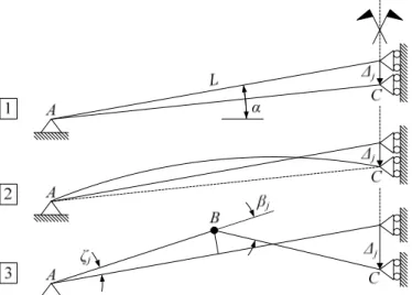
Considering all the previous hypotheses, a beam may be idealized according to the simplified model depicted in Figure 14.1, where L is its total length, i.e. the distance between the central and the lateral studs. Under the enforced displacement ∆j, the beam is assumed to respond through three steps:
-During the pre-buckling phase (Figure 14.1), the beam is elastically and plastically shortened under a strong axial force. This behavior dominates until buckling occurs, as depicted on Figure 14.2.
-During the post-buckling phase (Figure 14.3), as the beam is still submitted to an increasing displacement ∆j, a plastic
hinge is finally formed at the middle of the structure.
Figure 14.Equivalent mechanical model of an individual beam.
From Figure 14.1, it is clear that the axial shortening ∆Lj of
the beam in the pre-buckling phase and the associated normal force Nj are given by:
(
)
(
)
(
L L)
EA N L L L L j j j j j ∆ = ∆ − + − = ∆ 2 2 sin cosα α (15)where E is the Young’s modulus and Aj is the area of the beam
cross-section, as represented on Figure 13. Applying the virtual velocities principle to the previous system finally leads to:
δ α α ∂ ∆ ∂ ∆ − ∆ + ∆ − = j j j j j j L L L N P sin 2 sin 2 2 (16)
with ∂∆j / ∂δ = Yj / YP according to (14). Nevertheless, the
solution provided by (16) is only valid as long as no buckling occurs. The beam may buckle when the compressive force Nj
exceeds a critical value Ncr,j given by the Johnson-Ostenfeld
formula.
Once Nj ≥ Ncr,j, the post-buckling phase is activated. This
time, the resistance is mainly dominated by bending effects that are concentrated at the middle of the beam (point B on Figure 14.3). In accordance with [12], if we suppose that the cross section depicted on Figure 13 belongs to class 1, then it is possible to reach the maximal plastic moment Mj at point B.
This allows for a relative rotation characterized by an angle βj
that can be evaluated as a function of ∆j through some
geometrical considerations. Applying the virtual velocities principle to the system depicted in Figure 14.3 leads to:
δ β ∂ ∆ ∂ ∆ ∂ ∂ = j j j j j M P (17)
Finally, Pj has to be chosen in accordance with the normal
force Nj acting on the beam. If Nj is small enough, the resistance
is given by equation (16) characterizing the pre-buckling mode. On the contrary, if Nj exceeds the critical limit, the resistance
has then to be calculated by (17) for the post-buckling phase. Once Pj is known, the next step is to evaluate the contribution
Ps of the central stud.
5.2 Resistance of the central stud
It was already mentioned on Figure 12.3 that the central stud was submitted to an imposed rotation γ that may now be quantified with help of the developments made in the previous section. Considering Figure 14.3, it is clear that the rotation at the central stud (point C) is equal to βj. However, as ∆j is
different for each beam, we have βj+1 ≠ βj and the portion of the
central stud located between the beams j and j + 1 is submitted to the following differential rotation:
1 1 1− ≤ ≤ − = j+ j j M j β β γ (18)
which means that the central stud is submitted to torsion. Therefore, if we denote by MT the torsion capacity of the stud,
the application of the virtual velocities principle leads to:
∑
∑
− = + + + − = + + + ∆ ∂ ∂ − ∆ ∂ ∂ = ⇔ ∂ ∆ ∂ ∆ ∂ ∂ − ∂ ∆ ∂ ∆ ∂ ∂ = 1 1 1 1 1 1 1 1 1 1 M j j j j j j j P T s M j j j j j j j T s Y Y Y M P M P β β δ β δ β (19)In the previous formula, MT is parameter that has to be
properly evaluated by the user. A good approximation may be to calculate MT by idealizing the central stud as a box-girder or
as beam with an I-shaped cross section. Moreover, it is worth noting that the lateral stud is also submitted to torsion because
ζj+1 ≠ ζ j (Figure 14). However, the rotations ζ j are too small in
comparison with βj to produce large plastic dissipation at the
lateral support. This phenomenon is therefore neglected in the present approach.
Finally, the resistance Pg in the global deforming mode may
be found by applying equation (13), where the different Pj are
given by (16) or (17) according to the value of Nj, and where Ps
is to be found by applying (19). 6 APPLICATION EXAMPLE
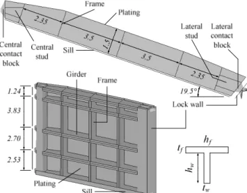
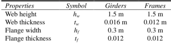
The simplified analytical approach exposed here over may now be applied to a given lock gate. The aim of this section is to compare the curve P(δ) obtained by the present simplified method with the one provided by simulating a collision with the finite element software LS-DYNA. The gate considered for this example is the one depicted on Figure 15 (where only one leaf is represented). It is made of five girders and three frames, having the dimensions listed in Table 1. As stated before, the contact blocks are located at the same level than the girders. For this example, the plating thickness is equal to 0.022 m.
The struck gate is made of mild steel, exhibiting first an elastic behavior characterized by a Young’s modulus E of 210 GPa and a yield stress σ0 of 235 MPa. Once this stress is
reached, the material is flowing plastically without any limitation, as rupture is disregarded.
The numerical model of the gate is made of 176682 Belytschko-Tsay shell elements (see Hallquist [13] for more information), with a regular mesh of 0.05 x 0.05 m. No beams elements are used.
In order to have a more or less realistic representation of the support conditions, the sills and the lock walls are also modeled (see Figure 15). Once again, Belytschko-Tsay shells are used, but they are this time associated to a perfectly rigid material, which means that no deformations are likely to appear on the supports. As the contact is simulated by using a penalty algorithm, the support mesh size is chosen to be similar to the one used for the gate.
The top of the bow impacts the gate at a distance of 7.5 m measured from the bottom of the lock. The shape of the striking vessel is characterized by the following parameters (Figure 3): p = 6.5 m, q = 8 m, hb = 5.6 m, ϕ = ψ = 85°. Its displacement is
4000 tons and its initial velocity is 2 m/s. It is only made of 20652 Belytschko-Tsay shells and is defined as a non-deforming body. In order to provide good contact conditions with the gate, the mesh is quite refined near the impact point (0.05 x 0.05 m).
Figure 16 shows the results obtained after a numerical simulation of the collision, where the striking ship was considered as perfectly rigid. The resistance given by the
present approach is also represented on Figure 16. As it can be seen, the agreement between the two curves is satisfactory.
1.5
hw
Figure 15. Main geometrical dimensions of the gate [m].
0 2000 4000 6000 8000 10000 12000 14000 16000 0 0,1 0,2 0,3 0,4 0,5 0,6 0,7 0,8 0,9 R és is ta n ce P ( k N ) Penetration δ (m) Analytical Numerical
Figure 16. Comparison of the resistance curves P(δ) obtained by LS-DYNA (numerical) and by the present approach (analytical).
7 CONCLUSION
In this paper, we present a simplified analytical procedure to evaluate the ability of a steel mitered gate to withstand a symmetric impact. We provide some explanations on the way to estimate the resistance in both the local and global modes. Finally, in order to apply our developments to an entire gate, we make a comparison with the resistance obtained through finite elements simulations. For this example, the present simplified method provides quite satisfactory results in a very short time, which may be relevant for pre-designing lock gates. As a matter of comparison, it takes more or less 10 hours to get the resistance curve by using LS-DYNA on a computer equipped with an i7-3770 Intel Core Processor, while the present simplified procedure leads to a reasonable approximation in 10 seconds only.
As a final comment, it worth keeping in mind that rupture of the constitutive material is not considered in this article. Regarding watertightness, the post-failure behavior of lock gates is not the prior matter of concerns, but it should be relevant to investigate it when considering robustness for example.
Table 1. Dimensions of the frames and of the girders
according to Figure 15.
Properties Symbol Girders Frames
Web height hw 1.5 m 1.5 m
Web thickness tw 0.016 m 0.012 m
Flange width hf 0.3 m 0.3 m
Flange thickness tf 0.012 0.012
REFERENCES
[1] Le Sourne H., 2007, “A Ship Collision Analysis Program Based on Super-elements Method Coupled with Large Rotational Ship Movement Analysis Tool”, International Conference on Collision and Grounding of Ships, ICCGS-2007, pp. 131-138.
[2] Lützen M., Simonsen B.C., Pedersen P.T., 2000, “Rapid Prediction of Damage to Struck and Striking Vessels in a Collision Even, International Conference of Ship Structure for the New Millennium: Supporting Quality in Shipbuilding, Arlington.
[3] Simonsen B.C., 1998, “Ship Grounding on Rock – I. Theory”, Marine Structures, Vol. 10, pp. 519-562.
[4] Le Sourne H., Rodet J.C., Clanet C., 2002, “Crashworthiness Analysis of a Lock Gate Impacted by Two River Ships”, International Journal of Crashworthiness, Vol. 7, pp. 371-396.
[5] Buldgen L., Le Sourne H., Rigo P., 2012, “Simplified Analytical Method for Estimating the Resistance of Lock Gates to Ship Impacts”, Journal of Applied Mathematics, Vol. 2012.
[6] Jones N., 1997, “Structural Impact”, Cambridge University Press, Cambridge.
[7] Zhang S.M., 1999, “The Mechanics of Ship Collisions”, PhD. thesis, Department of Naval Architecture and Offshore Engineering, Technical University of Denmark. [8] Buldgen L., Le Sourne H., Besnard N., Rigo P., 2012,
“Extension of the Super-Elements Method to the Analysis of Oblique Collision Between two Ships”, Marine Structures, Vol. 29, pp. 22-57.
[9] Hong L., Amdahl J., 2008, “Crushing Resistance of Web Girders in Ship Collision and Grounding, Marine Structures, Vol. 21, pp. 374-401.
[10] Simonsen B.C., Ocakli H., 1999, “Experiments and Theory on Deck Girder Crushing”, Thin-Walled Structures, Vol. 34, pp. 195-216.
[11] Amdahl J., 1983, Energy Absorption in Ship-Platform Impact, PhD. thesis, Department of Marine Technology, Norwegian University of Science and Technology.
[12] European Committee for Standardization, 2003, “Eurocode 3: Design of steel structures – Part 1.5: Plated structural elements”, prEN 1993-1-5:2003, Brussels. [13] Hallquist J.O., 2006, “LS-DYNA Theory Manual”,
ANNEX A
ADDITIONAL FORMULAE FOR SUPER-ELEMENT 1
In this appendix, we give the mathematical formulae required to evaluate the resistance opposed by a SE1 to the progression of the striking vessel. The membrane energy rates listed in formula (6) have the following expressions:
(
δ α)
δ δ α σ d a b a b a t dE p ⋅ ⋅ − + = 2 1 1 1 1 1 2 0 1 sin 3 3 cos 2 (A1)(
δ α)
δ δ α σ d a b a b a t dE p ⋅ ⋅ − + = 2 1 2 1 2 1 2 0 2 sin 3 3 cos 2 (A2)(
δ α)
δ δ α σ d a b a b a t dE p ⋅ ⋅ + + = 2 2 1 2 1 2 2 0 3 sin 3 3 cos 2 (A3)(
δ α)
δ δ α σ d a b a b a t dE p ⋅ ⋅ + + = 2 2 2 2 2 2 2 0 4 sin 3 3 cos 2 (A4)Introducing formulae (A1) to (A4) in equation (6) finally leads to the following resistance:
(
) (
)
+ − + + = 2 2 2 1 2 2 2 1 2 1 0 sin sin sin 1 3 3 2 α δ α δ α δ δ σ a a a a b b S t P p (B2) where S = (a1 + a2) (b1 + b2) cos² α.ANNEX B
FOLDING PROCESS FOR SUPER-ELEMENT 2
This appendix provides some additional information on the way to derive the individual resistance Pi characterizing a SE2.
The procedure is similar to the one followed by Zhang [6], except that we have here to consider a more complex indentation a(δ). From Figure 8, it is clear that:
− = ⇔ = + H a H a H 2 ) ( 1 arccos 2 ) ( cos 2 θ δ θ δ (B1)
The incremental form of the preceding equation may then be found by differentiation:
(
δ)
δ δ θ ad H a H d ∂ ∂ − − = 2 2 ) ( 1 1 2 1 (B2) By assuming that the folding height H is small in comparison with the lengths b1 and b2, the bending energy ratemay be approximated by:
(
) ( )
θ σ d b b t dEb p 4 4 1 2 2 0 ⋅ + = (B3)where 4dθ is the total rotation rate for the six plastic hinges AC, CE, CD, AB, EB and BD shown on Figures 7 and 8. The rotation rate dθ given by (B2) may be introduced in (B3) to get equation (8).
Let’s now consider the membrane energy rate. As depicted on Figure 8, it is clear that the indentation of fiber AC is a(δ). If we suppose that the indentation w(z,δ) of any fiber located at the depth z (with 0 ≤ z ≤ 2H) is linear, we have:
− ⋅ = H z a z w 2 1 ) ( ) , ( δ δ (B4)
and assuming that H is negligible in comparison with b (b = b1
or b2), the deformation of a fiber is given by:
δ δ δ ε δ ε wd b z w d b z w ∂ ∂ = ⇒ = 2 2 ) , ( ) , ( 2 1 (B5) For all the fiber located in the area (x,z) ∊ [0 ; 2H] ⨉ [0 ; b1], the total membrane energy rate may be found by:
∫
∫
⋅ ∂ ∂ ⋅ = H b p m d dz w z w b dy t dE 2 0 0 2 0 ( , ) δ δ δ σ (B6)which is valid for b = b1 or b2. Differentiating w(z,δ) in (B4)
and then introducing the result in (B6) leads to the formula (9) giving dEm. In all the previous equations, H is left as a
parameter that may be found by minimizing the mean crushing force over one fold. This one is given by:
∫
⋅ = H i i P a da H P 2 0 ) ( 2 1 (B7)Introducing (B3), (B6) and (10) in (B7), it is possible to obtain the following result:
(
)
+ + = 2 1 3 2 1 0 4 2 2 bb H t H b b t Pi p p π σ (B8) and the optimal value of H is found by minimizing (B8). In accordance with Zhang [6], this optimum is:3 2 1 16 3 b b t H= π p (B9)
All the mathematical formulae given here above are valid as long as the fold is not completely closed. However, for values of a(δ) increasing 2H, we make the hypothesis that the folding process previously described is simply repeated as many time as necessary. Consequently, the individual crushing force is still obtained by (10), but a(δ) has to be replaced by a(δ) – 2jH, where j is the number of folds already completely closed.
Annex C
FOLDING PROCESS FOR SUPER-ELEMENTS 3 AND 4
The aim of this appendix is to derive the optimal value of the folding height H characterizing a SE4 coupled to a SE3. To do so, it is necessary to minimize the mean forces (calculated over one fold) provided by both SE3 and SE4. The first one is directly given by (11) and, for convenience, is simplified in the following manner:
H t K
Pi = σ0 p (C1)
where K is an appropriate function of k. The second one may be found by considering (B8), where b1 has to be replaced by b
- kH and all the contributions of b2 are removed. Doing so, we
obtain: − + − = kH b H H kH b t t Pi p p 2 0 8 π σ (C2)
Adding (C1) and (C2) leads to the mean crushing force of a SE4 coupled with a SE3:
− + − + = kH b H H kH b t KH t Pi p p 2 0 8 π σ (C3)
which has to be minimized with respect to H. Unfortunately, it is not possible the find an analytical solution satisfying exactly this requirement. Under the assumptions that H 2 and that kH is negligible in comparison with b, the minimization may only be conducted on the two first terms of (C3). Doing so, the following optimal value of H is found:
K bt H p 8 π = (C4)
which may be used in equations (11) and (12).