Site
investigations
on
cavernous
limestone
for
the
Remouchamps
ViaduGt,
Belgium
by A.C.
WALTHAM*,
G.
VANDENVEN**
and C.M.
EKt
POOR GROUND CONDITIONS on cavernous limestone created severe difficulties at the
sites
of
four
piers
of
the
Remouchamps Viaduct. The discovery, during excavationsfor
foundations,
of
large open
cavitiesprompted
a
major
re-appraisalof
siteinvestigation procedure,
and also
some redesign of the viaduct structure.lntroduction
The
RemouchampsViaduct
carries the Liègeto
Arlon sectionof the
E9 motorway across the Amblève valley, incised into the Ardennes plateau of southern Belgium.lt
is939m long and carries four lanes of traffic,
81m above the Amblève River. Of its eleven piers and two abutments, seven are founded
at
least partly
on
limestone,and
workassociated
with the
difficult
groundconditions
was
responsiblefor a
15o/oincrease
in
overall cost.The
viaduct was completed in 1980 at a cost of 14OO million Belgian Francsl.Site
geology
Bedrock
in the
Remouchamps areaconsists
of
sandstones, limestones and shalesof
Devonian age. They are stronglyfolded,
so that they are
locally veftical orovefturned,
and they
contain many small faults. The sandstones are generally massiveand
strong,but the
shales are commonlyaltered
and
weathered
to
considerable depths, and areof
low bearing capacity.The limestones
at the
site were already knownto
be generally massive, fine grained and strong, but alsoto
have been subjectedto
extensive karst solution. Open surfacesinkholes
are not
abundant,but
there
isintense sub-soil solution with open fissures
at
depth. Many
cavesare
known
in
theregion, including
the
Remouchamps show cave (Fig. 1) which has 2 SOOm of mappedpassages,
mostly
in
excess
of 5m
indiameter2.
Within the
limestone sequence, there are zones of shale interbedded with aminor proportion of impure limestone; these include the Macigno melange, consisting of a
limestone-shale conglomerate,
and
some black dolomite beds.Superficial deposits consist mainly of thin
sand
and
gravel
alluvium,together
with-Dr. A.C. Waltham, PhD, Department of Civil Engineering,
Tre nt Polytec h n ic, Notti ng ha m.
--lr. G. Vandenven, l. 1.9., Service géologique de Belgique, Bruxelles.
tDr. C.M. Ek, DrSc, Laboratoire de Géomorphologie et de
Géologie du Auabrnaire, Université de Liège.
16
Ground Engineeringhigher level
terracesof
similar
material.Many
of
the
limestone slopes are coveredwith very thin clay colluvium.
lnitia!
site investigation
The line of the motorway was determined
by
topographical constraints,and
it
was recognisedthat
a major viaduct across the Amblève valleywould
haveto
be founded paftly on limestone, paftly on shale and partlyon
sandstone.After
a
desk study
to determine the broad geological structure, aprogramme of cored boreholes was carried
out
with
laboratory testing of the cores. At least four boreholes were placed on each pier site.A
seismic refraction survey was used toexplore the depth of the all uvial terrace at the
Arlon
end
of
the
viaduct (Fig. 2l,.
A microgravimetric survey was not used on the limestone outcrop; a similar survey had been doneat
the
siteof
the
adjacent Secheval viaduct, but had been found to have limitedvalue
in
an
area
of
such
structural and topograph ic complexitf .A
pinnacled rockhead on heavily fissured limestone was foundat the
siteof
pier 6,which
was therefore moved 27m towardsArlon off the limestone.
At
both the site forpier 5 and the new site for pier 6, weathered shales indicated the need for spread footings and low net loadings. Elsewherethe borehole survey gave no indication
of
unsound rock, and excavation work commenced.The
north abutment
Excavation for the foundations of the north abutment revealed an open cave just below
the
surface;its
single passage was 2-3m high and wide and descended steeply to the west before, becoming choked 65m from its entrance (Fig. 3). Eight boreholes had been drilled onthe
site,but
all
had missed the cave.Six out
of
the eight
bores recordedsolution fissures
and
cavities
in
the limestone, though almost all were less than 4Ocm across, and they revealed no pattern to indicate more extensive solution.Shuttering was placed
in the
cave 18m below formation level, and the cave was thenfilled with a fluid cement from there up to a level of
-5m.
Weathered rock round the cavemouth was removed to a depth of 5m and the
whole
then
replacedwith a
lean concrete,providing
a
solid
base
on
which
the foundations were laid.Pier number
2
After four
boreholeshad
revealed noindication
of
poor
ground,
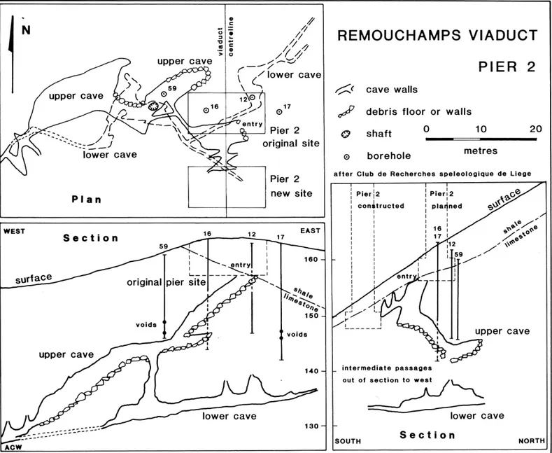
excavation to formation level exposed the roof of an open cave passage. Figure 4 shows how this wasthe upper part of a complex system of cave passages, directly below the pier site, which
had been missed by all
the
boreholes. Theupper
passagesin
the
cave consist
of solutionrifts
and wider bedding controlled chambers, long abandoned by any stream; their roofs are collapsing, leaving their floors covered in breakdown debris, and they maycontinue
eastwardsbeyond
the
boulderchokes
which
block them.
The
lower passages contain an active streamway, fed by various rifts in process of active solution. Borehole 59 would have revealed the caveif it
had
beena few
metres deeper, andborehole
12 would
have
intersected thelower cave
at a
much
greater
depth. Boreholes 16 and 17 both passed between open cave in the upper system. The logs from boreholes59 and 17
both record open or clay filled fissures intheir
lower parts, butthese have no apparent relationship
to
the revealed cave.The volume, extent and complexity of the
cave
system,
in a
zone
of
extensively corroded rock, precluded a massive concretefilling. The site
of
the
viaduct
pier
was therefore moved 13.5m towards Arlon, afterdetailed ground examination; construction could then proceed after only a small part of
the
cave had been filled. And atthe
same time, the extentof
site investigation on the limestone was greatly increased with respectto the other pier sites.
Revised
site investigation
When
the
extentof the
solution cavities beneath pier 2 was recognised, much more intensive exploration was instigated at all the.pier
sites
on
limestone.
The
principletechnique employed
was
probing
withprecise
measurementsof
the
rates
ofpenetration; though this was of limited value
in other ground conditions, it was found to be
inexpensive and very effective for identifying limestone solution voids, which were either
open
or filled with
young unconsolidatedsediment.
lt
was
recognisedthat
karstic solution cavities could exist anywhere, in norecognisable pattern; also while small voids
were
hazardousat
shallow depths, largervoids could be tolerated
at
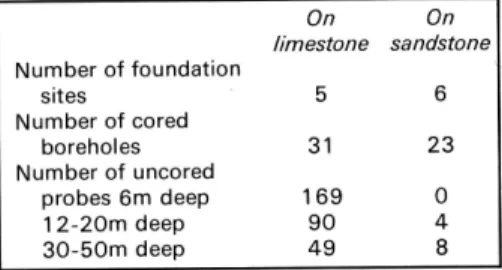
greater depths. Consequently, probeswere drilled
to
6m depth on a 2m grid, with drilling to 3O-5Om depth on a 1Om grid. ln practice, there was some flexibility in both the grid pattern, andNumber of foundation sites Number of cored boreholes Number of uncored probes 6m deep 1 2-2Om deep 3O-50m deeP
On
On limestone sandstone56
31
23169
0904
498
TABLE I.
COMPARISON BETWEEN SITE INVESTIGATION TECHNIOUES EMPLOYED ATPIER AND ABUTMENT SITES ON LIMESTONE
AND ON SANDSTONE
Some zones of rapid penetration werethen
checked
by
downhole
cameras,but
the scope of this was limited by the clayfills
inthe caves. Table 1 showsthe extent of drilling
on the limestone, in marked contrast to that carried out on the non-cavernous sandstone
outcrops.
ln the
event,the
intensive griddrilling
did
not
discover anyfurther
large cavitiesto
match those beneaththe
initial siteof
pier 2.The
final
appraisal
of
the
limestone recognised a pinnacled rockhead broken byconical
depressionscontaining
clay
andcorroded limestone blocks.
This
passed downwards into a zone of limestonewith clay filled pockets and caves of extremelyvariablemorphology.
At
greater depthsthe
mainsolutional openings
in
the
limestone werecorroded fissures, creating
a
network system, and locally enlargedto
shafts andgalleries
1-2m
in
diameter.
The
mostintensive cavitation
was found
in
the limestone close to the contact with shale orFis. 1 (Left). Topographic and geologic map
of
Remouchamps Viaduct area
Macigno beds.
This
wasto
be
expected, because corrosive surface water collects onthe impermeable rocks, and flows onto the limestone
to
immediately sink into fissureswhere
it is
then
capable
of
extensive solutional action; the underground boundaryalso acts as
a
barrierto
groundwater flowwithin the limestone, deflecting waterto flow
parallel
to it.
Solutional activity
andconsequent
cavitation
is
therefore concentrated inthe
limestones adjacent tothe
impermeable outcrops.An
additionalnotable
factor
at
Remouchampswas
the marked variabilityof
ground conditions; atthe
northern abutmentand pier
2
sitessignificant caves
were
found,
while
the intermediate site of pier 1 was on sound rock. The above description might apply to anysite
on
karst
limestonein
temperate ortropical
environments.The
depthsof
thepinnacles
and
of the
more
intensely cavernous zones, relateto
local factors oftopography, drainage and climatic history.
Gonstruction
and
foundation
design
At
all sites,the
limestone required some treatment and improvements. The depth ofthe main solution zonewastoo great to place
formation level below
it
on
unweathered rock; a limited net of karstic cavities is likelyto
occur throughout
the
thicknessof
alimestone. Clay pockets in exposed rockwere cleared out, and all fissures in the limestone were grouted
with
concrete, using plugs insome cases to restrict dispersion. Grout was also injected into the exploration boreholes, with a mean takeof 1 1 7kg in a mean depth of
1 7m. Thesetechniques proved successful on
the sites of piers 1, 3 and 4, and on the new Fig. 3 (Below). The cave at the north abutment
concrete fill
Fig. 2. Long section of Remouchamps Viaduct and bedrock geology
site of pier 2 rêlocaied away lrom the
cave
excellent sxample of the unpredictabilityol
and pier 2. With the benefit ot hindsight, thesystem.
the nature ofcavernous limestone. lngeneral
hundreds of probes employed in the second At pier 5,limestoneand dolomiteprovided
lerms. it is impossiblelo predict the extentof
phasecould be
deemed overreactive. But a good foundation ata depth ol around8m,
solution
cavitiesin
unexposedlimestone
large
numbers
of
drilled holes
arebut part of the footing was unavoidably
on
beneathany given site.
However,al
the
unavoidableto
satisfactorily prove
thatshale.
This was
heavily
weatheredand
Remouchampssitq an
indication
that
hazardous caviiies do not exist.lfths
roof ofrequired removalto a depth of 1 5m before
an
câvities were even more likely to occurthan
the cave at pier 2 had remained unexposed, assymetric concretepad could be
placed
normal
could be laken
from
both
the
just below formation level, the consequence inside a diaphragmwall.
presenceol
known maior caves nearbyand
of later collapse and failure could have been The initial site for pier 6 proved to beover
alsothe
locationof the
site
closeto
the
extremely serious. ln view of the low cost of limestone bedroclçbut
directly
abovea
limestone margin.ln
suchcircumstances
probing by destructive drilling, compared toburied sinkhole
9m
deep
ând lOm
in
there
is
no
alternativeto
detailed
and lotal
proiect
costs,
excessive
sitediamct€r
cut
into
a
hoavily
pinnacl€d
exhaustivesite
investigationwith
high
investigation in areas ofcavernous limestonerockhead
beneath
8m
of
alluvium,The
density
borehole
grids.
Geophysical
is probably impossible. êxtremely corroded natureof
the
ground
explorationof
cavsrnous limestone is verymade
it
unsatisfactory,and
the
pierwas
difficult
to
interpret, and normally canact
Refêlences
relocated
onto
a
rockheadof
shaleand
only as an aid to efficient planning of smorc
t.
Nachgrgaele, R, Mahieu, L., Latout, F., wouteÉ, sandstone. Evenon the
new site,
the
conclusivedrilling
programme.Boreholes
M.
e
caby,
u
(tg8o):
-Le viâduc
decalcareous shale was so heavily
weathered are
expensive,but
eyena
maior
drilling
Bêmouchâmps". Annsles des travsux publicsthat
it would accept only a very limitednet
programme, carried out at an early stagein
de Belgique, 5, 4'l 5-452loading, and the pier had to be founded on
a
project planning, is €conomically viablewhen
2.
Ek c.M. llg7olt "cdrte Géologiquo dotâ Groftecellular caisson, 29m in diameter and
13m
it can eliminate even more expensivedelâys
de Bemouchampg Belgique." Annales de ladeep, sunk into
place.
to the constructiontimetable.
Société céologique de Bêlgique. 93, 2a7-292.Thê small numbers
of
boreholesin
the
3.
Vandenven,G
(1978):
-DescriptioîGonclusion
initial
viaduct
site
investigation
were
qéotoqiqué du site du viaduc de Sèchsvôt àThe
foundalion conditions
at the
inadequâte-
as
demonstrated
by
Remouchamps." Service géologique deRemouchamps
Viaduct
provided
an
subsequent eventsat the
northâbutment
Bêlgique, Professional Papêr, 153,27pp.Fig.
4.
The cave and the boreholes at the site of pier 218
Ground Engineeringupper cave
E/
?
./t
Ë
./7E -/i/
i
/--//
.,/
lower cave
t\ (-.original site
Pier
2new site
'-:-::-J_J
\S\
lower
cave
-:\
REMOUCHAMPS
VIADUCT
PIER
2
6ic
cave walls
"/
debris
floor or
walls
A shaft
O
10
20
o
borehote
Ë
after Glub de Recherches speleologique de Liege
16