THESIS PRESENTED TO
ÉCOLE DE TECHNOLOGIE SUPÉRIEURE
IN PARTIAL FULFILLMENT OF THE REQUIREMENTS FOR THE DEGREE OF DOCTOR OF PHILOSOPHY
Ph. D.
BY
Ana Beatriz MARTINS AGUIAR
ELECTROMAGNETIC MODELING OF LARGE HYDRO ELECTRICAL GENERATORS USING 2D FINITE ELEMENT METHOD
MONTREAL, DECEMBER 17TH 2014
This Creative Commons licence allows readers to download this work and share it with others as long as the author is credited. The content of this work can’t be modified in any way or used commercially.
BOARD OF EXAMINERS
THIS THESIS HAS BEEN EVALUATED BY THE FOLLOWING BOARD OF EXAMINERS
Prof. Kamal Al-Haddad, Thesis Supervisor
Electrical Engineering Department at École de technologie supérieure
Dr. Arezki Merkhouf, Thesis Co-supervisor Institute de Recherche Hydro-Québec
Prof. Stéphane Hallé, President of the Board of Examiners
Mechanical Engineering Department at École de technologie supérieure
Prof. Ambrish Chamdra, Member of the jury
Electrical Engineering Department at École de technologie supérieure
Prof. Aldo Boglietti, External Evaluator Independent
Industrial Electrical Engineering Department at Politecnico di Torino
THIS THESIS WAS PRESENTED AND DEFENDED
IN THE PRESENCE OF A BOARD OF EXAMINERS AND PUBLIC NOVEMBER 28TH 2014
ACKNOWLEDGMENTS
First and foremost I would like to thank Dr. Kamal Al-Haddad and Dr. Arezki Merkhouf for supervising my work over the last five years. Their expertise, guidance and support were fundamental for the accomplishment of this thesis.
I would also like to express my deepest gratitude to Dr. Bachir Kedjar for agreeing to be the second reader and to Dr. Raja for proof-reading and correcting the English.
My gratitude also goes to the members of my doctoral committee: Dr. Aldo Boglietti, Dr. Stéphane Hallé and Dr. Ambrish Chamdra, for evaluating this thesis and providing valuable comments.
I wish to thank my colleagues at the IREQ (Institut de Recherche Hydro Québec), Claude Hudon, Melanie Lévesque, Federico Torriano, Samuel Cupillard, Hind Dirani and Jemimah Akiror, for the useful and pertinent discussions regarding electrical machines and core losses. I am deeply grateful to my Canadian family that I have formed over the last few years. My special thanks go to Priscila Wakamatsu, Alvaro Tamayo, Michelle Peixoto, Luana Bezerra and Rodrigo Suguimati. I am also grateful to my close friends, Patrick Verhaar, Manuella Luiz, Stéphane Gazaille and Cecilia de la Moura. Your presence and support have allowed me to overcome many obstacles. Thank you very much.
I would like also to acknowledge my long time friends from Brazil, Livia, Sandra Paula, Merielle, Katyane and Grisangela, for their great and enduring friendship. Even when I was far away, they were always there to support me and cheer for me.
Thanks as well to my Master’s thesis advisor, Dr. Joao Onofre Pereira Pinto, who guided me into the academic world and encouraged me to pursue a PhD.
Last, but definitely not least, I would like to thank my family for all their support, especially my mother Tereza Cristina, my father Marcus Sergio and my brothers Luis Felipe and Marcus Sergio, for their love and unconditional support and encouragement.
ELECTROMAGNETIC MODELING OF LARGE HYDRO ELECTRICAL GENERATORS USING 2D FINITE ELEMENT METHOD
Ana Beatriz MARTINS AGUIAR
ABSTRACT
With the ever increasing of the demand for electrical energy, the need for additional power has already become a reality in the energy supply market. In this context, increasing the power output of existing generators is considered as a promising and beneficial option. Unfortunately, the available methods today do not allow exploiting the full power potential of the existing generators with a precise evaluation of the impact of this increase on the residual lifetime. The challenge in uprating a large existing machine therefore is increasing the output power within the safety limits and without reducing the reliability of the system. One of the goals of Hydro-Québec is to develop new techniques which permit identification of units with potential for up rate. The understanding of the electromagnetic fields inside the generator and their implication in the losses is the first step to fulfil this goal. This thesis focuses on analyzing the electromagnetic field and establishing the magnetic core losses for different machine configurations and operating conditions. The electrical machine in question is a low-speed, salient poles synchronous generator. Initially, a literature review of the related subjects published in the last 20 years was investigated. Secondly, modelling analysis and simulation of large electrical machines using commercial software to compute the losses at the steady state was also done. Moreover, validation of this work and analysis is done using measurements of losses with emphasis on the core losses and magnetic flux density. The core loss matrix generated by FEM was also compared with the thermal calculation and measurements of the hotspots of the machine. The results from FEM simulation in comparison to the experimental measurements are presented for two machines (Manic 21 and Rapide-des-Quinze). The simulation and experimental results were in a good agreement.
Keywords: extrapolation of the power output, cut and bypassed stator coil, finite element
MODÉLISATION ÉLECTROMAGNÉTIQUE DES GRANDS GÉNÉRATEURS HYDRO ÉLECTRIQUES UTILISANT DES ÉLÉMENTS FINIS 2D
Ana Beatriz MARTINS AGUIAR
RÉSUMÉ
Avec l'augmentation de la demande d'énergie électrique, la nécessité de la disponibilité de la puissance supplémentaire est déjà devenue une réalité du marché de l'approvisionnement en énergie. Dans ce contexte, l’augmentation de la puissance de sortie des générateurs existants est considérée comme une option prometteuse et bénéfique. Malheureusement, les méthodes d'aujourd'hui disponibles ne permettent pas exploiter le plein potentiel des générateurs existants et l’augmentation de puissante de sortie peut accroître l'impact sur la durée de vie résiduelle. L'un des objectives d'Hydro-Québec est de développer de nouvelles techniques qui permettent d'identifier les unités avec le potentiel pour l’augmentation de puissance. La compréhension de la distribution des champs électromagnétiques à l'intérieur du générateur et son implication dans les pertes est la première étape pour atteindre cet objectif. Cette thèse consiste à analyser la distribution des champs électromagnétiques et d'établir les pertes correspondantes dans le noyau magnétique pour différentes conditions d'exploitation. Initialement, une revue de la littérature liée à ce sujet publié sur les 20 dernières années a été investiguée. Deuxièmement, la modélisation et la simulation des grandes machines électriques pour calculer les pertes à l'état d'équilibre ont également été analysées. En outre, pour des raisons de validation, les mesures portant sur les pertes fers et flux magnétique ont été effectuées. Par ailleurs, la matrice de perte dans le noyau calculée par FEM a été utilisée par le module de calcul, ainsi les températures prédites sont comparées aux mesures. Les résultats de la simulation FEM et la comparaison avec les mesures expérimentales sont présentées pour deux machines (Manic 21 et Rapide-des-Quinze). La simulation et les résultats expérimentaux sont en bon accord.
Mots-clés: extrapolation de la puissance de sortie, bobine de stator coupés et contournés,
TABLE OF CONTENTS
Page
INTRODUCTION ...1
CHAPTER 1 LITERATURE REVIEW ...7
1.1 Hydro-generator previous studies ...7
1.1.1 Core loss determination ... 8
1.1.2 Damper currents and damper bar losses determination ... 10
1.2 Analytical and numerical methods used in electromagnetic simulation ...12
1.2.1 Analytical methods ... 12
1.2.2 Numerical methods ... 13
1.3 Losses in electrical machines ...19
1.3.1 Joule losses... 19
1.3.2 Stray losses... 19
1.3.3 Iron losses ... 20
1.4 Iron loss models ...29
1.4.1 Steinmetz equation and its modifications ... 32
1.4.2 Loss separation... 36
1.4.3 Hysteresis model ... 40
1.5 Upgrade and uprating of hydro-generators ...41
1.6 Fault detection in electric machines ...43
1.7 Conclusions ...46
CHAPTER 2 COMPONENTS HYDRO-GENERATORS ...47
2.1 Machine components ...48 2.1.1 Stator ... 49 2.1.2 Rotor ... 57 2.1.3 Airgap ... 64 2.2 Studied machines ...65 2.2.1 Manic 21 ... 66 2.2.2 Rapide-des-Quinze ... 69 2.3 Conclusions ...70
CHAPTER 3 EXPERIMENTAL SET-UPS AND EXPERIMENTAL RESULTS ...71
3.1 Magnetic material measurements ...71
3.1.1 Magnetic resistivity ... 74
3.1.2 Magnetic material losses ... 74
3.2 Magnetic field measurements ...75
3.3 Segregated loss...77
3.3.1 Open-circuit test ... 78
3.3.2 Short-circuit test ... 78
3.3.3 Calorimetric test ... 79
3.4.1 Magnetic material measurements ... 80
3.4.2 Manic 21 measurements ... 83
3.4.3 Rapide-des-Quinze measurements ... 93
3.5 Conclusions ...97
CHAPTER 4 ELECTROMAGNETIC MODELING OF ELECTRICAL MACHINES ....99
4.1 Analytical method: d-q-0 model ...101
4.2 Maxwell’s equations ...103
4.2.1 Constitutive laws ... 105
4.2.2 Boundary conditions ... 106
4.3 Different domains of electromagnetism ...107
4.3.1 Electrostatic ... 108
4.3.2 Electrokinetics ... 108
4.3.3 Magnetostatic ... 109
4.3.4 Magnetodynamic... 110
4.4 Potential formulations ...110
4.4.1 Magnetic vector potential formulation (A, V-A) ... 110
4.4.2 Electric vector potential formulation (Τ−Ω,Ω) ... 112
4.5 Governing equations for the different parts of the machine ...113
4.5.1 Stator core ... 114
4.5.2 Stator winding ... 115
4.5.3 Rotor core... 116
4.5.4 Damper bars ... 117
4.5.5 Airgap ... 118
4.6 Finite element method ...119
4.6.1 Weak formulation and it’s application for magnetodynamic problems ... 120
4.6.2 Discretization of the domain and shape functions ... 122
4.6.3 Gauge conditions and source fields ... 124
4.6.4 Matrix formulation ... 126
4.6.5 Imposition of displacement constraints (movement of the machine) ... 127
4.6.6 Methods of solution of the system ... 128
4.7 Synchronous salient pole generator model ...128
4.7.1 Mesh features ... 131
4.7.2 Choice of time step ... 133
4.7.3 External circuit ... 134
4.8 Hypothesis and simplifications ...137
4.8.1 Geometric model ... 137
4.8.2 Equivalent model depth ... 138
4.8.3 Magnetic material characteristics ... 139
4.8.4 Types of simulation: voltage driven x current driven ... 140
4.9 Magnetic losses models ...142
4.9.1 Solid loss model ... 142
4.9.3 Implemented model for core loss computation ... 146
4.9.3.1 Stator loss model ... 147
4.9.3.2 Rotor loss model ... 148
4.10 Conclusions ...149
CHAPTER 5 SIMULATION RESULTS AND MODEL VALIDATION ...151
5.1 Initial model ...153
5.2 Model calibration ...154
5.2.1 The influence of the mesh ... 155
5.2.2 The influence of the excitation current ... 160
5.2.3 The influence of the airgap length ... 162
5.2.4 The influence of the voltage driven simulation ... 168
5.2.5 Influence of the magnetic material characteristics ... 171
5.3 Segregated losses ...172
5.3.1 Open circuit ... 173
5.3.1.1 Magnetic induction and its distribution ... 175
5.3.1.2 Damper bar currents ... 181
5.3.1.3 Core losses ... 182
5.3.2 Short-circuit ... 184
5.3.2.1 Magnetic flux induction and its distribution ... 185
5.3.2.2 Damper bar currents ... 187
5.3.2.3 Core losses ... 188
5.4 Core loss computation at different load operating conditions ...190
5.4.1 Magnetic flux density and its distribution ... 191
5.4.2 Damper bar currents and its losses ... 197
5.4.3 Magnetic losses and its distribution ... 201
5.4.3.1 Core losses calculation with the implemented model ... 205
5.5 Temperature of the damper bars ...208
5.6 Conclusions ...212
CHAPTER 6 INDUSTRIAL APPLICATION OF THE DEVELOPED TECHNIQUE ..213
6.1 Extrapolation of Manic 21 (>100% load) ...214
6.1.1 Extrapolation condition – 170 MVA at 14.5 kV... 218
6.1.2 Extrapolation condition – 188 MVA at 14.5 kV... 220
6.1.3 Discussions for the extrapolation conditions at 14.5 kV ... 221
6.2 Cut coil study of Rapide-des-Quinze ...228
6.2.1 Circuit current calculation with one bypassed coil ... 231
6.2.2 Circuit current calculation with four bypassed coils ... 233
6.3 Conclusions ...236
CONCLUSION ...239
LIST OF TABLES
Page
Table 1.1 Comparison of 10 different iron loss models investigated ...30
Table 2.1 Hydro Quebec energy production ...47
Table 2.2 Winding sequence example ...56
Table 2.3 Hydro stations studied...66
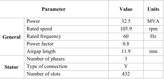
Table 2.4 Generator design and electrical parameters for Manic 21 ...67
Table 2.5 Generator design and electrical parameters for Rapide-des-Quinze ...69
Table 3.1 Magnetic flux density B (T) ...86
Table 3.2 Differences between simulated and measured machine ...87
Table 3.3 Segregated losses on a similar machine (Manic 24) ...88
Table 3.4 Computed losses for Manic 21 ...90
Table 3.5 Losses division on Rapide-des-Quinze ...96
Table 3.6 Computed losses for Rapide-des-Quinze ...97
Table 4.1 Basic shape functions ...124
Table 4.2 General machine parameters ...129
Table 4.3 Stator parameters ...129
Table 4.4 Rotor parameters ...130
Table 4.5 Analysis setup parameters ...130
Table 5.1 Compute magnetic core loss with different meshes (time step of 27.5 μs) ...157
Table 5.2 Core loss and current line results for different excitation current (airgap of 15.875 mm) ...161
Table 5.4 Computed core loss with different magnetic materials ... 172
Table 5.5 Summarized simulated results ... 189
Table 5.6 Experimental values of phase current and power factor ... 191
Table 5.7 Computed magnetic core loss models ... 206
Table 5.8 Summary of the computed magnetic core loss with different models for the measured load conditions ... 207
Table 5.9 Comparison between measured and computed damper bar temperature ... 210
Table 6.1 Simulated and expected values for stator phase current (14.5 kV) ... 222
Table 6.2 Simulated results for machine operating over the nominal conditions ... 222
Table 6.3 Computed rotor and stator temperatures for 170 MVA and 188 MVA ... 226
Table 6.4 Computed rotor and stator temperatures for 150 MVA and 165 MVA ... 227
Table 6.5 Damper bar losses – load operation (86% and 100%) ... 236
Table 6.6 Stator Kh coefficient ... 243
LIST OF FIGURES
Page
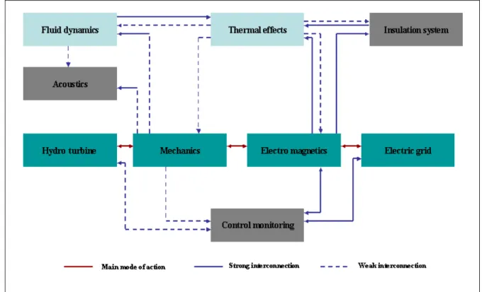
Figure 1.1 Physical domains and coupling between them ...43
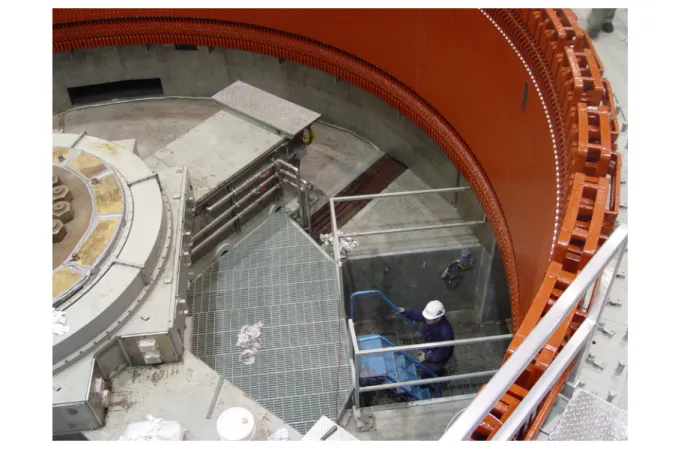
Figure 2.1 Hydro generator ...48
Figure 2.2 Teeth dimensions – a) designed machine, b) smaller teeth dimensions ...50
Figure 2.3 Stator of a large synchronous machine ...53
Figure 2.4 Stator core geometry ...53
Figure 2.5 Stator winding geometry ...54
Figure 2.6 Stator winding ...55
Figure 2.7 Rotor Manic 21 ...58
Figure 2.8 Pole shoe shape ...59
Figure 2.9 Pole shape definition – a) 2 radii b) 3 radii ...60
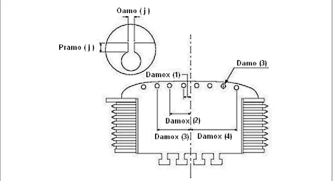
Figure 2.10 Damper bars positioning ...61
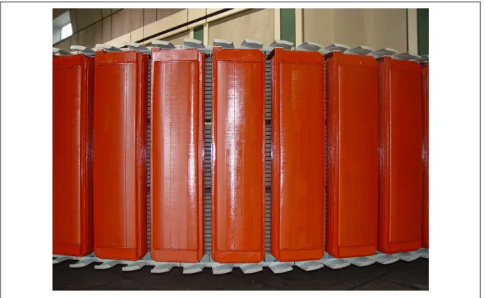
Figure 2.11 Rotor poles and damper windings in a typical hydro generator ...62
Figure 2.12 Field winding ...63
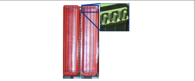
Figure 2.13 Rotor, stator, coil sensor and RTD sensor during instrumentation stage ...65
Figure 2.14 Capability curve ...68
Figure 3.1 Epstein test ...75
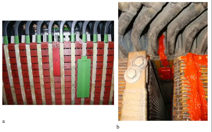
Figure 3.2 Coil sensor placed on the stator – a) Manic 21, b) Rapide-des-Quinze. ...77
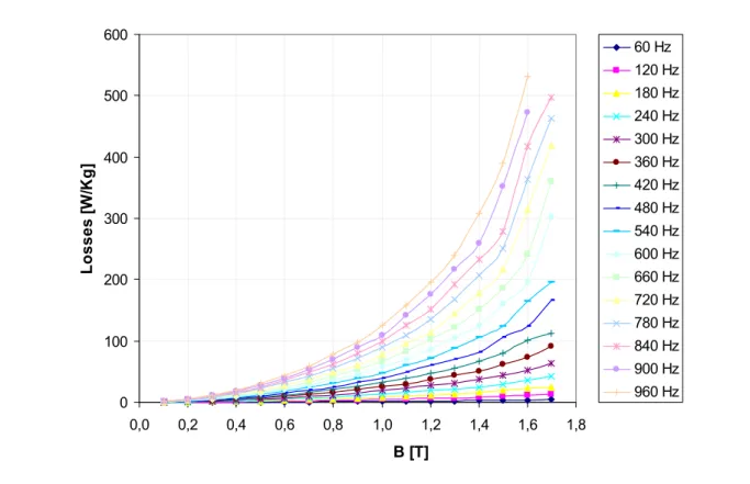
Figure 3.3 Specific core loss measured at multiple frequencies (stator) ...81
Figure 3.4 BH curve (stator)...81
Figure 3.5 Specific core loss measured at 60 Hz (rotor) ...82
Figure 3.6 BH curve (rotor) ...82
Figure 3.8 Airgap flux density for open-circuit operating condition (rated voltage) .... 83
Figure 3.9 Airgap flux measurements for the four measurement conditions ... 85
Figure 3.10 Airgap flux measurements for the four measurement conditions ... 86
Figure 3.11 Losses separation in percent for Manic 24 ... 88
Figure 3.12 Losses separation ... 89
Figure 3.13 Open-circuit and short-circuit saturation curves – Manic 21 ... 91
Figure 3.14 Temperature sensors at pole face ... 92
Figure 3.15 Measured damper bar temperature at different operating conditions ... 93
Figure 3.16 Airgap flux measurements for 86% nominal load ... 94
Figure 3.17 Open-circuit and short-circuit saturation curves – Rapide-des-Quinze ... 95
Figure 4.1 Phase diagram of a salient-pole generator ... 102
Figure 4.2 Application problems of Maxwell’s equations ... 108
Figure 4.3 FEM for electromagnetic problems ... 120
Figure 4.4 2D geometric elements ... 122
Figure 4.5 Mesh definition for each component ... 132
Figure 4.6 Stator representation ... 133
Figure 4.7 External circuit: damper winding bars circuit ... 136
Figure 4.8 External circuit at load condition ... 136
Figure 4.9 Boundary conditions ... 138
Figure 5.1 Extrapolation steps ... 152
Figure 5.2 Five poles machine model ... 153
Figure 5.3 Model calibration ... 155
Figure 5.5 Current density distribution in the damper bar for: a) 23 elements
per bar, b) 90 elements per bar and c) 933 elements per bar ...158
Figure 5.6 FFT analysis of the damper bar current for different mesh configurations (nominal load) ...159
Figure 5.7 Total core loss as a function of the excitation current for nominal load ...162
Figure 5.8 Total core loss as a function of the airgap length for nominal load ...165
Figure 5.9 Computed magnetic flux density using the measured airgap length ...166
Figure 5.10 Core loss distribution – a)case 11.96 mm, b) 14.93 mm ...167
Figure 5.11 Excitation current (voltage driven simulation) a) transient current envelope, b) zoom in the last 0.1s ...169
Figure 5.12 Phase current (voltage driven simulation) ...170
Figure 5.13 Phase voltage (voltage driven simulation) ...170
Figure 5.14 Stator, rotor and total loss as a function of time (voltage driven simulation) ...171
Figure 5.15 Meshing 2D of 5 poles pitch model 122.6MVA hydro-electric generator ...173
Figure 5.16 Open-circuit curve ...174
Figure 5.17 Open-circuit voltage x core loss curve ...175
Figure 5.18 Magnetic flux density and flux lines at open-circuit ...176
Figure 5.19 Magnetic flux induction B (airgap) - open-circuit (arc airgap (red) and arc rotor (blue)) – normalized distance ...177
Figure 5.20 Spectral analysis – magnetic flux density B (airgap) – open-circuit ...178
Figure 5.21 Spectral analysis - magnetic induction B (rotor) ...179
Figure 5.22 Comparison between measured and simulated flux density, at rated voltage, 13.8 kV, no-load (9H sensor) ...180
Figure 5.23 FFT magnetic induction B (airgap) ...180
Figure 5.25 Damper bar loss for each bar in pole 1 – open-circuit operation ... 182
Figure 5.26 Flux lines distribution and core loss distribution at open-circuit ... 183
Figure 5.27 Core loss distribution between stator and rotor on open-circuit operation ... 184
Figure 5.28 Magnetic flux density and flux lines at short-circuit ... 185
Figure 5.29 Magnetic flux induction B as a function of a normalized distance ... 186
Figure 5.30 Magnetic induction B (airgap) as a function of the time ... 187
Figure 5.31 FFT analysis of damper bar currents ... 188
Figure 5.32 Magnetic core loss and flux lines distribution ... 189
Figure 5.33 Flux lines and magnetic flux density distribution for 71% of nominal load ... 192
Figure 5.34 Flux lines and magnetic flux density distribution for 100% of nominal load ... 192
Figure 5.35 Flux lines and magnetic flux density distribution for 120% of nominal load ... 193
Figure 5.36 Magnetic flux density in the airgap and in the pole face as a function of the normalized distance for 71% of nominal load ... 194
Figure 5.37 Magnetic flux density in the airgap and in the pole face as a function of the normalized distance for 100% of nominal load ... 194
Figure 5.38 Magnetic flux density in the airgap and in the pole face as a function of the normalized distance for 120% of nominal load ... 195
Figure 5.39 Simulated and measured magnetic flux density in the airgap as a function of the time for 71% of nominal load ... 196
Figure 5.40 Simulated and measured magnetic flux density in the airgap as a function of the time for 100% of nominal load ... 196
Figure 5.41 Simulated and measured magnetic flux density in the airgap as a function of the time for 120% of nominal load ... 197
Figure 5.43 FFT of the damper bar currents for nominal load ...199
Figure 5.44 FFT of the damper bar currents for 120% of nominal load ...199
Figure 5.45 Damper bar losses as a function of the line current in p.u. ...200
Figure 5.46 Damper bar losses per bar (pole 1) ...201
Figure 5.47 Magnetic core loss distribution and flux lines for 71% of nominal load...202
Figure 5.48 Magnetic core loss distribution and flux lines for nominal load ...202
Figure 5.49 Magnetic core loss distribution and flux lines for 120% of nominal load...203
Figure 5.50 Comparison between rotor and stator core loss at 71%, 100% and 120% of nominal load ...204
Figure 5.51 Division of the load core loss into hysteresis and eddy current for nominal load...205
Figure 5.52 Computed magnetic core loss with different models for the measured load conditions ...208
Figure 5.53 Measured and calculated damper bar temperature for 3 different load conditions ...211
Figure 5.54 Calculated rotor temperature ...211
Figure 6.1 Line current versus excitation current for different load conditions ...217
Figure 6.2 Open-circuit core loss curve and tendency curve ...218
Figure 6.3 Flux distribution in the air gap for 170 MVA: a) as a function of time, b) as a function of the distance ...219
Figure 6.4 Flux distribution for 170 MVA ...219
Figure 6.5 Flux distribution in the air gap for 188 MVA: a) as a function of time, b) as a function of the distance ...220
Figure 6.6 Flux distribution for 188 MVA at 14.5 kV ...221
Figure 6.8 Magnetic losses for 146.5 MVA, 170 MVA and 188 MVA ... 223 Figure 6.9 Stray load losses for 146.5 MVA, 170 MVA and 188 MVA
as a function of the I2phase ... 224 Figure 6.10 Losses for 170 MVA and 188 MVA for different core loss models ... 225 Figure 6.11 Magnetic flux density distribution and the core loss distribution for
165 MVA ... 228 Figure 6.12 17 poles machine model ... 229 Figure 6.13 Meshing 2D of a 32.5 MVA hydro electrical generator a) entire
machine, b) zoom of the 2D mesh ... 230 Figure 6.14 Current in p.u. per phase – load operation (86%) - 1 cut coil
circuit B2 ... 232 Figure 6.15 Current in p.u. per phase – load operation (100%) - 1 cut coil
circuit B2 ... 232 Figure 6.16 Comparison of experimental and simulation results 86%
with 1 cut coil ... 233 Figure 6.17 Current in p.u. per phase – load operation (100%) - 4 cut coils circuit B2 ... 234 Figure 6.18 Current in p.u. per phase – load operation (86%) -
4 cut coils circuit B2 ... 235 Figure 6.19 Magnetic flux density and flux lines distribution for an asymmetrical
LIST OF SYMBOLS
A Magnetic vector potential (Wb/m) B Magnetic flux density (T)
D Electric flux density (C/m2)
E Electric field intensity (V/m) H Magnetic field intensity (A/m) I Current (A)
J Electric current density (A/ m2)
L Inductance (H) M Magnetization (A/m) R Resistance (Ω) Φ Magnetic Flux (Wb) ε Electric permissively (C2/ N.m2) μ Magnetic permeability (H/m) ρ Electric charge density (C/ m3)
σ Conductivity (Ω -1m-1)
kh Hysteresis coefficient kc Eddy current coefficient ke Extra-losses coefficient
INTRODUCTION
Market opportunities have always lead utilities to look for different ways to maximize generating capacity, without reducing the reliability of their equipment. In liberalized market with increased competition, retooling/refurbishing an existing generator offers a good opportunity to the utilities to expand the life time of their power generation facilities with limited financial investments.
Manufacturers have failed to follow the recent developments and progress made in the field of numerical simulation due to the fact that the use of empirical models worked quite well in the past. Although, they have considerable experience in the design of generators and in the solution of associated problems, these techniques do not allow accurate evaluation of the real thermal behaviour of the generators and also they do not permit to design effective corrections.
A major challenge for all the utilities is to identify those existing generators with large potential for uprating. When such generators are identified, precaution should be taken at this stage, specifically, if certain parts of the generators are considered for refurbishment. The best candidate is the one which has the potential to achieve minimally reduced safety margin with minimal or no change of the components and at the same time without decreasing the reliability of the system.
On the other hand, over the past years, the advances of numerical models have enabled manufacturers to design generators with a better understanding of every aspect of the machine. Before, the tendency was to use larger safety margins to lower the risk. Consequently, some of the generators built a few decades ago have larger potential for uprating than newer machines.
On the rotor side, partial refurbishment can imply rewinding of the rotor poles only or substitution of the entire rotor. On the stator side, rewinding for more modern insulation class is sometimes sufficient to achieve greater output, but in some cases the stator core and a change of number of slots and winding pattern may be also necessary.
With the possibility to uprate the existing generators, the Research Institute IREQ of Hydro Québec created AUPALE project. AUPALE stands for "AUgmentation de la Puissance des
ALternateurs Existants ".
Determining the electromagnetic, mechanic, fluid and thermal limits in the stator and rotor is one of the tasks of the AUPALE project. Hence, the main objective of this thesis is to develop an accurate model and perform an exact evaluation of the rotor and stator core losses in hydro generators. For that, advanced electromagnetic numerical modeling was carried out in order to predict the exact behaviour of the modified generator before any uprating to calculate the impact of this increase on the parameters such as, flux density distribution, open circuit voltage harmonics, damper bar currents, damper bar losses, extra copper losses, open circuit and short circuit core losses, torque and force harmonics, transient and sub-transient reactances.
From the electromagnetic point of view, it is not possible to separate rotor and stator electromagnetic components. However, through simulation this separation is possible; the study of the rotor and stator core losses is another task of this thesis. Besides, the proposed research will contribute for a better understanding of the electromagnetic losses in rotating electrical machines. The obtained results will ultimately help tomorrow's engineers to design hydroelectric generators with lower losses, and therefore higher efficiency.
The analytical and numerical analysis of electromagnetic simulations for different operating conditions provides better understanding of the generator’s operation. Thus, the definition of the existing operating conditions and the possible increase of energy production can be a
thorough examination of the current scenario and consequently may reduce the investments for the construction of new generating facilities to fulfil the ever increasing demand of electrical energy.
The global trend over the last twenty years is on modeling using Finite Element Method (FEM) to determine more accurately the actual capabilities and limitations of the generators. However, due to the size of the hydro machines (some over 10 meters in diameter) and the limitations of computational capacities, the FEM method was used only in the last five years for large hydro machines. Even though the FEM is the most recommended method for electromagnetic simulation, its results are not absolute and always need to be validated on site or with measurements on small-scaled laboratory prototypes.
After the electromagnetic simulation is completed, the core loss distribution results are used by the thermal experts as one of the inputs to determine hot spots of the machine. Besides, vibration and the fluid studies are added and the interactions of each study are correlated. At the end of the project (AUPALE), the decision on the suitability of the specific machine for uprating is presented. In addition, improvements necessary to increase the performance of the machine can be proposed.
Recently, another industrial application problem was introduced to the thesis, which consisted in performing an electromagnetic diagnostic of a damage hydro generator. The studied machine is operating at 86% of its nominal power output due to one of the stator bars is cut and bypassed. In this case, the machine had to be entire modeled and a large model was created to analyze the spatial distribution of the magnetic flux and more importantly the distribution of the stator current in each of the 4 terminals of the three phases.
Finally, the results can be complemented with the analysis on the economic viability of the uprating such as comparing the life reduction cost (if there is) of the generator with the
increased power and the increased revenue generated with the increased energy production by the machine.
Methodology:
To complete the electromagnetic simulation of an existing machine, seven stages have to be performed, as following detailed:
1. Accurate data collection on existing generators. The measured data shall contain:
• exact geometry of the generator; for that, performed measurement must be done to define unknown parameters;
• measurement of electrical parameters of the generator (for instance: voltage, current, damper bar currents) at different operating conditions such as: load variation (69%, 100% and 120%), open circuit test and short-circuit test;
• characterization of the magnetic material of the rotor and stator for low and higher frequencies to determinate the characteristic curves such as: peak induction - power loss (for specific frequencies) and B-H by the Epstein test.
2. Accurate electromagnetic modelling to determine the losses distribution in different parts of the machine with a focus on the rotor side;
3. Measurement of the magnetic flux on the machine, for that an induction sensor is used at some predetermined points of the airgap;
4. Simulation of the machine studying the impact of some input parameters in the simulation result, including airgap change and bypassed stator bars;
5. Study of different core loss models;
6. Extrapolation of the machine to study the possibility to increase the power output; 7. Comparison of the simulated and experimental results for validation purposes.
Contributions:
The objective of this thesis is to analyze by finite element simulation the electromagnetic behaviour of a large hydro generator. The proposed research will contribute to a better understanding of the electromagnetic losses phenomena in rotating electrical machines.
Fractional machines are modeled and the results are compared with measured ones for further analysis to determine if the machine’s power could be uprated. The calculation of losses, distribution of the losses and flux, phase current and voltage, damper bar currents are analyzed. The studied method based on FEM determines precisely the locations where higher magnetic fluxes are located.
Another contribution of this thesis is the calculation of the rotor and stator core losses. Before the proposed technique, the core losses were computed for the entire machine. The comprehension of how the losses are distributed in the machine will allow improvement of the machine's efficiency for a possible redesign of some of the components.
The results achieved in one generator are going to be extrapolated for others in the same power facility. Finally, the results can be extrapolated to model and perform economic analysis that could estimate the life reduction cost of the generator and compare with the increased power generation and the associated additional revenue and profit generated.
Engineering contributions:
• solution to real problems for the industry;
• some work has been done in parallel with the software company to improve the software by adding some parameters that allow to study large machines;
• comparison of simulation and experimentation results in large hydro machines; • application of methods to calculate different losses;
• separation of the core losses by simulation from hysteresis and eddy current losses; • spatial distribution of the losses by simulation (for the experimentation only an average is
achieved);
• extrapolation of the power output machine to analyze the magnetic losses by simulation and avoiding real experiments that could be harmful to the machine;
• study of the thermal dilatation of the machine pertaining to the magnetic flux density and the core loss;
• study the bypassed bars and its interference in the magnetic flux distribution;
• comparison between current driven and voltage driven simulation methods and the advantages and disadvantages of both.
Outline of the Thesis:
This work is divided into an introduction to the subject of the thesis and six chapters. The first chapter presents the review of the relevant researches regarding synchronous machines during the last 20 years, where a background study of the analytical and numerical methods is provided. The second chapter consists in the description of the machine under study. The third chapter contains the experimental set-up procedures and the data obtained. Chapter 4 comprises the mathematical formulation behind the finite element method. Chapter 5 presents the simulation results of many different conditions of Manic 2, in addition, it details, the simulation results and a comparison with the experimental ones. Chapter 6 includes the two application examples of the discussed method; the first one was related to the analysis of a possible power increase of Manic 2, followed by the study of another hydro generator named Rapide-des-Quinze that operates with disconnected damage coils. Finally, the conclusions regarding the power output increase and the electromagnetic diagnostic of a damage machine are presented and also the areas for future works and thesis improvement.
CHAPTER 1 LITERATURE REVIEW
In this chapter, the literature review of correlated theses, master's dissertations and relevant papers are organized by topics. The focus is on worldwide works (Canada, USA, Brazil, France, Finland, etc.) from expertise areas such as numerical methods, magnetic materials, synchronous machines, hydro-generators, core loss determination and damper winding bar currents calculation. The topics were presented in more than 50 Master's and PhD thesis over the last 20 years.
1.1 Hydro-generator previous studies
In this section, previous work regarding salient pole machines is presented. The reference list concerns the core loss determination, the damper currents and damper bar losses, the eddy current and the thermal computation of hydro-generators.
In 1999, the thesis entitled “Modeling of Synchronous Machines for Systems Studies” was presented by Mohamed Labib Awad. He proposed a new method based on the machine dimensions and material properties to predict the operational inductances of the machine. The author took into consideration the linear reluctance matrix, the saturation effects, the eddy current distribution and the depth penetration for the development of his frequency-domain model. In the end, the author compared the result of his model and the measurements of a large turbo alternator concluding that the model results are essentially accurate.
For salient pole synchronous machines, a standstill frequency response test was proposed to determine the direct and quadrature axis operational impedances by (Bortoni et al., 2004). The advantage of the proposed method is that the machine can be tested with the rotor at standstill and stopped at any arbitrary position. However when the research was conducted
on small machines, some errors were found when comparing the proposed theory with the standard procedure.
In 2004, Merkhouf et al. investigated the different tools and practices for large hydro-generator design used lately. The advanced electromagnetic design using time-stepping finite element methods; and the permeance model were detailed. Moreover, the use of computational fluid dynamics method allows the prediction of the fluid flow, heat transfer and mass transfer. The utilization of numerical and analytical models permits the determination of modifying design constraints and the improvement of the new machines.
In 2011, Ranlöf’s thesis was entitled “Electromagnetic Analysis of Hydroelectric Generators”. This thesis was the aggregation of different studies involving large hydro-power generators performed by the author. In this study, the theory of salient-pole machines, the equivalent circuit model, the finite element generator model and the coupled field-circuits are described. Besides, the permeance model was implemented to determine the effects of the damper windings on the open-circuit armature voltage waveform. Other topic presented in this thesis is the core loss estimation with comparison of the experimental and simulated results. He found that the effect of harmonics and flux rotation increase the total core loss of about 28% on an average.
1.1.1 Core loss determination
A paper computing the losses in large hydro generators was published by (Traxler-Samek et
al., 2006). The optimization of the loss calculation of salient-pole generators in a design
program using statistical methods is presented. With this improved technique, the manufacturer can estimate and guarantee machine losses (no-load iron losses). The method simplifies the decision process for special and cost-intensive design improvements.
In 2008, Znidarich studied the stator core of large hydro-generators, the physical construction features including stator core end region stepping, radial ventilation ducts, stator core clamping systems and segmented or continuously stacked stator cores. Besides, the losses in the stator core including hysteresis and eddy-current and the effects of alloying, rolling and heat treatment, grain direction, etc are presented (Znidarich, 2008a). The continuation of the last work covers the definition of the stator core loss for open-circuit and short-circuit and the way that they are segregated. The evaluation of the stator core condition is done by the stator core ring flux test; the author states that this test is the traditional and most appropriate test for assessment of the core condition. An alternative method for finding shorted lamination is called ELectromagnetic Core Imperfection Detector (ELCID). However, the last method does neither estimate the core loss nor the severity of the hot spot. The paper concludes with a summary of the important factors that must be considered when specifying new stator cores for hydro generator upgrades (Znidarich, 2008b).
Large hydropower generators were also investigated by Ranlöf et al. in 2009. It is emphasized that the total core loss prediction comparing different core loss prediction schemes with no-load measurement. Also, the authors observed that the rotational loss is closely related to the stator slot geometry. Finally, the proposed time-domain model with constant loss coefficients was found to predict the total core loss to be about 65% of the measured no-load loss in large hydro generators (Ranlöf et al., 2009).
Another paper that computes the losses of a hydro-generator was presented by Bertalanic et
al. Measurements were carried out in 12 hydro-generators onsite using the calorimetric
method. It is well known that it is one of the simplest methods to determinate the losses of closed water cooling hydro-generators. The measurements were done in two different approaches: off-line and online. The authors concluded that the determination of losses based on the online tests gives more accurate results (Bertalanic et al., 2010).
The core loss under no-load was calculated for a 1000 MW air cooled hydro-generator using FEM. The authors compared the simulation results of the traditional analytical method, the steady-field method (magnetostatic) and the transient field method to compute the yoke and teeth iron losses. For both numerical methods, the non-linearity of the core material and the uneven distribution of the magnetic flux density were considered and the exact value and distribution of the iron loss were obtained (Weili et al., 2012).
1.1.2 Damper currents and damper bar losses determination
The damper bar currents of a large salient-pole synchronous machine with skewed stator slots were measured using two Rogowski coils placed on the end ring of two different poles, the results can be found in Karmaker et al. (2005). Besides, a comparison between measured and calculated damper bar currents at load were presented for a 16 MVA hydro-generator.
Numerical and analytical methods were combined for the determination of the damper bar currents in large salient-pole synchronous generators under eccentricity conditions. The proposed method is based on the magneto-static FEM and on the resolution of the electrical circuit differential equations. This combined method showed faster results when compared to the transient magnetic FEM simulations with almost the same level of precision (Keller et al., 2007).
The damper winding losses were calculated for large hydro-generators on open circuit and load conditions by an analytical method by Traxler-Samek et al. (2008b). The current distribution in the damper bars is calculated by an analytical algorithm based on the air-gap permeance function and uses a numerical integral approach for the calculation of the induced voltages in the damper bars. The proposed approach was compared with transient finite element method showing good agreement with faster results.
The computation of the current distribution and the associated power losses in damper-winding, The damper-winding bars of salient-pole synchronous machines due to the tooth-ripple pulsations and the stator-winding armature-reaction harmonics on open-circuit and load conditions are detailed in Traxler-Samek et al. (2010a). The calculations were based on the air-gap permeance model, and a numerical integration for the calculation of the induced damper-bar voltages was used. This integration allows the consideration of the local variation of the air-gap. The method is based on an equivalent network of the damper bar winding containing all the bars of a section of the machine. This investigation didn’t take into consideration real test measurements. Instead, for validation purpose, the authors compared the proposed analytical algorithm with the traditional 2D finite element method for calculation of current and corresponding losses of damper windings.
Ranlöf et al. (2010) developed a semi-analytic permeance model to predict the open-circuit voltage harmonics and the damper winding losses. The authors considered integral slot armature winding generators and the centralization of the damper windings around the pole axis. Compared with the previously permeance model, two modifications have been suggested concerning the model of the damper bar reaction. First, the MMF of a damper loop was based on the observations of the actual radial flux paths in the airgap; and, the coupling between adjacent damper loops was included in the model. In general, the agreement between measured and calculated model was considered reasonable by the authors.
The additional losses on the rotor pole surface and the damper windings of 250 MW hydro-generator were calculated by time stepping finite element model. Besides, a 3D temperature field model was done and the temperature distribution was analyzed under rated voltage and no-load conditions. The authors concluded for this specific generator that the temperature distribution of the damper winding and end ring damp rises from end to axial centre (Feiyang
1.2 Analytical and numerical methods used in electromagnetic simulation
The electromagnetic simulation is the first stage of any study on uprating of an existing machine. This has been the subject of many publications (Zhan, 2010; Karneva, 2005; Zhong, 2010). However, the methods of calculation and measurement of the flow of electromagnetic energy have been studied since 1800's. An interesting review of the progress of the electromagnetic study is presented by Guedes, (1983).
The electromagnetic theory developed by Maxwell in 1873 was able to embrace electromagnetic phenomena such as Faraday’s law, Ampere’s law, Gauss’ law in a series of differential (or integral form) equations. The application of the time-dependent Maxwell’s equations and the boundary conditions allows the calculation of the electric and magnetic fields in a closed surface.
The Maxwell equations can be solved either by analytical, numerical or even the combination of both methods. For simple geometrical shapes, analytical method is still a good option, but due to the boundary and interface conditions, the numerical methods are usually applied for more complex structures.
1.2.1 Analytical methods
The range of possible problems which can be solved by using analytical methods are very restricted, because these methods only allow the determination of linear and simple geometric structures (mostly in 1D or 2D).
One of the models widely used to study the synchronous machine comes from Park Theory where the stator’s three-phase quantities are transformed and transferred to a new reference system, orthogonal and fixed to the rotor, known as direct and quadrature (d-q) axes. In 2004, another thesis was completed in Helsinki University of Technology regarding electric
machines and electromagnetic simulation. Entitled “Analytical Prediction of the
Electromagnetic Torques in Single-Phase and Two-Phase AC Motors” Mircea Popescu
discussed about the two axis d-q theory to the prediction of the electromagnetic torque. The developed models take into account the most important asymmetries of the motor configuration such as: different distribution, conductor dimensions and effective turns in the stator point of view and asymmetrical rotor cage, variable reluctance and permanent magnetic effects on the rotor side. The author stated that the developed mathematical models have been successfully used for education purposes (Popescu, 2004).
Galbraith, in his master's dissertation, presented a technique for the estimation of the synchronous generator parameters using time-domain responses (Galbraith, 2005). For the determination of machine parameters, some measurements were done such as: generator terminal voltages; generator terminal currents; field current; speed and gate position. Using Matlab software, the author searched for a way to facilitate the transfer from the field measurements to the simulation environment with respect to data conditioning by developing an analytical tool for processing of the field measurement data and estimating specific parameters using measured machine responses.
A revision of the electromagnetic transient simulation techniques for synchronous machine is presented in 2007. In this work, the d-q model, phase-domain model and voltage-behind-reactance (VBR) model were detailed. The study shows that the three models are equivalent in the continuous time domain when the time step is sufficiently small. For large time-steps, the VBR model shows better stability property and provides the most accurate results (Wang
et al., 2007).
1.2.2 Numerical methods
In 1983, Guedes (1983) performed an extensive survey on the numerical methods for analysis of the magnetic field of electrical machines. Finite difference method and the finite
element method were explained and the advantages and disadvantages of each were detailed through a comparative study. This thesis is a good reference to identify the differences between the different methods and the suitability of each to a specific application.
In 1994, Jin G. Zhu presented his PhD thesis entitled “Numerical Modelling of Magnetic Materials for Computer Aided Design on Electromagnetic Devices” at the University of Technology in Sydney, Australia. The focus of his work was on modelling of hysteresis loops with alternating magnetic fields. A new dynamic circuit model taking into account the hysteresis, eddy current, and anomalous losses was included to simulate the performance of magnetic cores with non-sinusoidal alternating flux and also with rotational flux (Zhu, 1994). As a continuation of his work, in 1998, he published a paper presenting improved formulations for rotational core losses in rotating machines (Zhu, Ramsden, 1998). Besides, in 2008, the author (with others) presented a revision of the measurement and modeling of rotational core losses techniques of soft magnetic materials used in electrical machines (Guo et al., 2008). This last paper presents an extensive survey on the measurement and modelling of rotational core losses. These publications focus on the practical applications to engineering.
In 1996, Jonathan Hill presented the master's dissertation entitled “Efficient implementation of mesh generation and FDTD simulation of electromagnetic fields”. In this study, the finite difference time domain (FDTD) was implemented in a parallel computer system for the analysis of the electromagnetic phenomenon. Moreover, an algorithm was used to produce the parallel implementation of the mesh generator. This dissertation detailed the steps regarding the generation of mesh in electromagnetic waves devices (Hill, 1996).
Besides, FDTD methods were also investigated by Chow et al. The authors used parallel computation for a high performance electromagnetic solution. (Chow et al., 2007).
In 2001, the thesis “Magnetic Field Analysis of Electric Machines Taking Ferromagnetic Hysteresis into Account” was presented by Július Saitz at Helsinki University of Technology. The author incorporated the vector hysteresis model into a 2D time-stepping solution through the fixed-point iterative technique. This method was applied to the magnetic field simulation and the computation of the core loss of three cage induction motors. The author concluded that even though the technique is rather slow, it is robust, reliable and it always converges (Saitz, 2001).
The 2D FEM was used to calculate the stator coil flux linkages taking into account the rotor motion by moving band technique. Kim et al. implemented a method to analyse the harmonic distortion factor of output voltage waveform of a synchronous generator using the discrete Fourier transform. Calculated and experimental results were compared for a 150 kW machine. The authors highlighted that the proposed technique can be useful for pole shape design optimization to satisfy the specification for maximum acceptable waveform distortion factor (Kim, Sykulski, 2002).
In 2002, Merkhouf presented a transient model based on 2-D time-stepping finite element method of a salient-pole synchronous machine. The simulation model took into account the saturation effects, the eddy current losses and the end effects for open-circuit and sudden three-phase short-circuit. The results obtained from simulation (voltage waveform, telephone influence factor and dynamic reactances) were compared with measurements in a large hydro-generator. The simulation leads to a better understanding of the complex physical phenomena occurring during sudden short circuits and therefore leads to more accurate prediction of machine model parameters at the design stage (Merkhouf, 2002).
A comparative analysis of different theoretical iron losses evaluations techniques coupled with finite element calculations and material modeling has been presented by (Bottauscio et
al., 2002). Two different aspects were considered in this study: the model of the
the eddy current and the hysteresis losses. The analysis was performed in a discrete space with a two-dimensional finite-element code using a voltage driven formulation. All the predictions of the developed models were in the same order; however the results were not compared to any test data.
In addition, time domain dynamic core loss model was proposed (Lin et al., 2004) to estimate core loss in both ferromagnetic and power ferrite materials with arbitrary flux waveforms. The model was applied to compute instantaneous core losses in small electromagnetic devices in both two-dimensional and three-dimensional transient finite element analysis. The authors concluded that their method is practical for industrial applications because it provides reasonable accuracy and all the necessary parameters are obtained directly or by the loss curves provided by the manufacturer.
Numerical methods can also be used for transient field-circuit coupled simulation analysis. Using finite integration technique to discretize the field part of the field-circuit model and external circuits that are treated as lumped parameters, a strong coupling was implemented by (Benderskaya, 2007).
A simulation of a 2D solid rotor synchronous machine was solved by finite element method by (Petite, 2008). In this master's dissertation, the steady-state solution behaviour in the presence of voltage inputs is solved using shooting-Newton method.
Zhan (Zhan, 2010) developed a finite element model for AC machine systems and also an efficient numerical solution for the system equations. The author analyzed the stray losses in AC machines under a variety of operations, design and manufacturing conditions.
The determination of equivalent circuit parameters based on FEM was investigated for synchronous machines (Chmelicek, 2010). Steady state and transient operation simulations were performed using FEM for the estimation of the generator reactance. For the steady state
operation, the reactance profile estimation was obtained from the magneto-static field solution. The estimation of transient and sub-transient reactances were obtained by sudden short-circuit method; and an automated Matlab script was developed in order to achieve precise curve fitting and more accurate results. The author states that software packages using FEM allow precise computation of field problems even with nonlinear material properties or time variance.
A 3D time-harmonic finite element analysis of the end-region of large-sized three-phase induction machines was studied by Lin (2010). In it, the electromagnetic and mechanical phenomena were carefully analyzed regarding the end-magnetic field, the stator end-winding leakage inductance, the eddy currents in the end shield and end frame and the end-winding forces and vibrations.
A combination of finite-element and analytical modeling technique (permeance model) was developed by Knight et al. (2001) to predict the damper winding effects and the force due to harmonic components. The combination of both the techniques reduces the computation time when compared to a full time-stepping finite element solution. Measured results from two different machines were presented and compared with the simulation ones. The combination of numerical and analytical methods for the determination of the power loss was also presented by (Keller et al., 2006) and (Knight et al., 2009 a, b).
Analytical methods were used in the past, but now are studied much less with the development of the numerical method. However, the analytical method still plays an important role when providing qualitative ideas about the data that would be calculated numerically. Besides, they are always used as a fast tool to validate the results of computational methods. For instance, analytical and numerical models were compared and validated by Traxler-Samek et al. (2010a); in it, the authors calculated the additional losses and the currents in the damper winding on open-circuit and load conditions.
The investigation and simulation of fields in large salient pole synchronous machine with skewed stator slots was the paper’s target by Karmaker and Knight. (2005). The authors developed a computational model combining finite element an analytical formulation based on the permeance model and analyzed the electromagnetic field distribution, the damper bar currents and the pole face iron losses on fractional stator slots per pole of the machine. Measured data show that skewing introduces a phase shift on the machine and a progressive increase in the magnitude of the flux density. The authors concluded that their simulation technique offered rapid simulation time and accurate prediction that can help the designers to better understand the impact that design changes may have on stray load losses.
An overview of the interfacing rotating machine models in transient simulation programs was presented by Wang et al. (2010). The authors studied the electromagnetic transient programs (EMTP) and also the state-variable-based simulation programs (SV).The EMTP based on the nodal equations enabled an efficient numerical solution. One of the well-known simulation programs is MATLAB/Simulink that is used to study the dynamics of the electrical systems.
Another thesis (Iamamura, 2011) dealing with turbo alternators was presented in 2011 where the aim was to develop methods to detect, locate and recognize faults. A combination of an analytical approach with a numerical model based on FEM was done and the simulation results were compared with other available methods to detect and locate the rotor faults. Both results are in a good agreement even at different operating points showing a good reliability of the method (Iamamura, 2011).
Finite element methods are widely used today by commercial organizations (Alstom, Andritz, GE, etc.) and also by the academy as an optimal tool to study the behaviour of the electromagnetic field distribution in an electrical machine (Traxler-Samek et al., 2006, 2008a, 2008b, 2010a, 2010b; Merkhouf et al., 2004, Karmaker et al., 2005; Wallin et al., 2010).
1.3 Losses in electrical machines
Losses in electrical machines can be divided as: joule loss, mechanical loss, stray loss and iron losses. In this section, the joule losses, stray losses and iron losses will be highlighted.
1.3.1 Joule losses
Joule loss, also known as I2R losses, is the ohmic heating loss that occurs in windings (stator, rotor and field windings) of a synchronous machine. The conductor resistance is temperature dependent; hence the Joule losses are also dependent on the operating temperature of the machine.
In the stator and field windings the Joule losses are computed using lumped resistance multiplied by the square of the currents; however in solid conductors like the ones in the damper bars, the losses cannot be computed in this way as the density of induced currents are not uniformly distributed in the cross section due to skin effect. Using a FEM technique the induced current density can be computed locally and consequently the Joule loss.
Joule losses are commonly used to describe the losses at fundamental frequency. However, harmonic currents and harmonic fields cause another component of Joule loss, which also can be treated as portion of the stray losses (Zhan, 2010).
1.3.2 Stray losses
Stray losses are related to Joule and iron losses for all harmonic currents and fields except the fundamental frequency. The stray losses are the remaining losses obtained when subtracting the fiction loss, the windage loss, the stator I2R losses, the rotor I2R losses and the iron losses
According to Merkhouf et al. (2008), the most relevant causes for harmonics in electric machines are:
• “space harmonics in the airgap permeance due to stator slotting; • space harmonics in the stator MMF due to winding in discrete slots; • space and time harmonics in the airgap permeance due to rotor slotting; • space and time harmonics in the rotor MMF due to winding in discrete slot.”
The stray loss in AC machines (induction, synchronous and permanent magnetic synchronous machines) was determined using time-stepped finite element technique by Zhan (2010). The traditional 2D FEM was modified to take into account the variations of the electromagnetic field along the machine’s axis. Simulation and test results under different load conditions were compared and the additional harmonic stray loss was investigated.
Another work including stray loss and induction machines was presented by Aoulkadi (2011). In it, different tests to lower the stray load losses due to the skin effect in the stator winding in generators for 1.5 MW wind turbines were implemented during the manufacturing process. The estimation of the stator load losses as result of the skin effect was performed through analytical models and the results were compared with those measured.
1.3.3 Iron losses
Iron losses are also known as open circuit core losses. According to IEEE- Std 115, the open circuit core losses are the sum of: losses in the stator core, teeth losses, end loss in cores and surface loss. These losses are explained as follows:
1. Losses in the stator core
The losses in the stator core happen in the annulus between the bottom of the slots and the outside diameter of the core.
2. Tooth-ripple losses
A very good definition of tooth-ripple losses was provided by Karmaker (1982, p.1122) as follow:
“Tooth-ripple losses are caused by the permeance variation along the airgap of a rotating machine due to the slotted structure of the armature so that the pole surface flux density in the airgap, instead of being uniform over the main part of the pole arc, has superimposed on it a ripple. This flux pulsation gives rise to parasitic eddy currents of diverse frequencies in the machine parts of which are in relative motion with respect to the ripple flux.”
The tooth ripple losses in practical poles with amortisseur windings have been measured by a calorimetric and a Poynting vector method (Karmaker, 1982).
In the calculation of tooth-ripple eddy-current losses in laminated poles, there are four important factors which should be considered (Sen 1971):
• the harmonics in the flux density distribution over the pole face; • the effect of eddy currents on the inducing or applied field; • the nature of the disturbance travel in pole-shoe material; • the skin effect phenomena.
In the problem of tooth-ripple losses, the pulsating flux is superimposed on a polarizing or unidirectional flux, and the resulting hysteresis loop is displaced from the origin of the magnetization curve by an amount depending on the mean flux density. The alternating
hysteresis loss due to this displaced loop is usually higher than the loss due to symmetrical loops having the same magnitude of flux pulsation (Fam, 1971).
Ueda, Ohta and Uenosono studied in real time the behaviour of the airgap flux distribution at the point where a synchronous generator actually supplies electric power to various loads for that; they developed a microprocessor-based instrument. The instrument, the principle and method of measuring the airgap flux distribution are described by the authors in (Ueda, Ohta, Uenosono, 1987).
3. End losses in cores
The leakage flux from the rotor pole shoe to the end of the stator core is alternating at generated frequency and therefore produces losses in the end faces of the stator core (Walker, 1981).
4. Surface losses (pole face losses)
Surface losses are basically functions of the flux density, the frequency pulsation, the quality and quantity of material and main dimensions and shape of slot and pole shoe.
Another type of classification of the iron losses was presented by Traxler-Samek et al. (2010b, p.174) where they were enumerated as:
1) “iron losses in the stator core including the effects of harmonics and rotating fields;
2) eddy current losses on the pole shoe due to tooth-ripple pulsation and stator winding armature reaction MMF;
3) eddy current losses in the stator clamping plates; 4) eddy current losses in the stator clamping fingers; 5) eddy current losses in the stator core end laminations; 6) eddy current losses in external metallic air guides.”
The variation of the magnetic flux in the core of an electric machine produces the iron losses, they can be classified as: hysteresis loss, eddy current loss and excess loss.
Hysteresis losses are associated with the magnetizing and re-magnetizing of the magnetic material. Hysteresis loss also depends on the volume and quality of the used magnetic material, maximum value of the flux density and frequency of electric current (Atallah et al.
apud Troitskaia, 2008), (Wakileh, 2003).
Otherwise, eddy current losses are the power associated with varying magnetic fluxes that induces EMFs in iron. Finally, the eddy current excess loss occurs due to microscopic eddy currents induced on the walls of moving domains. (Atallah et al. apud Troitskaia, 2008).
“Eddy-current loss is the power loss associated with the flow of eddy currents induced in the armature core of a rotating machine as a result of its rotation in the magnetic field or in the core of a transformer as a result of ac excitation” (Wakileh,
2003, p.32).
In the calculation of eddy current losses in solid pole face, two important factors should be considered. First, the harmonics in the flux density distribution over the pole face; the losses due to these harmonics form a very considerable part of total losses. The second factor is the effect of the eddy currents on the inducting or applied field due to slotting (Fam, 1971).
Eddy current loss is proportional to the square of the lamination material thickness and inversely proportional to the magnetic material resistivity.
The prediction of core loss in electrical machines and steel lamination sheets is a challenging task and many improvements of the existing calculation methods are reported over and over. For instance, the effects of the steel lamination core loss on transient magnetic fields were
presented by (Lin et al., 2008) based on core loss separation (hysteresis losses, classical eddy current losses and excess loss) in frequency domain.
Besides, the core loss calculation in laminated sheets was also subject of study by (Chen and Pillay, 2002), in this paper, the authors compared three different methods to compute the core loss of steel laminations. The first method was the using the Steinmetz equation considering that the maximum magnetic flux density does not overcome 1Tesla. The second method is a small modification of the first method and uses the domain wall theory to compute the core loss. In it, the component of the hysteresis loss is supposed to vary linearly with the flux density. The third method compared related hysteresis losses, classical eddy current losses and excess loss or also called anomalous loss for the computation of core loss. The authors concluded that the third method provide results that were closer to the measured ones.
“Hysteresis, eddy current and excess losses due to rotational flux in parts of a magnetic circuit where flux changes direction, have been found to comprise about 50% of iron losses in an induction motor” (Findlay et al. apud Troitskaia, 2008, ).
Another example of the improvement of the existing models for the calculation of the power loss is the addition of the rotational field reported by Ranlof et al. (2009), Zhu and Ramsden (1998), Guo et al. (2008)
The calculation of rotor surface losses in small to medium cylindrical synchronous machine was carried out by Hiramatsu et al. (2007). The authors proposed an estimation method to calculate the induced slot ripple loss on the rotor surface. Further, they compared different kinds of damper system using the finite-element method. The authors concluded that the conventional estimation of rotor pole loss was overestimated, due to overlooking the effects of slot pitch and damping effect of the flux ripple density.