UNIVERSITÉ DE MONTRÉAL
PATIENT POSITIONING FOR SURGERIES OF THE SPINE: HOW DOES IT IMPACT SPINAL GEOMETRY AND HOW CAN IT BE EXPLOITED TO IMPROVE SURGICAL
PROCEDURES
CHRISTOPHER DRISCOLL INSTITUT DE GÉNIE BIOMÉDICAL ÉCOLE POLYTECHNIQUE DE MONTRÉAL
THÈSE PRÉSENTÉE EN VUE DE L‟OBTENTION DU DIPLÔME DE PHILOSOPHIAE DOCTOR (Ph.D.)
(GÉNIE BIOMÉDICAL) DÉCEMBRE 2010
UNIVERSITÉ DE MONTRÉAL
ÉCOLE POLYTECHNIQUE DE MONTRÉAL
Cette thèse intitulée:
PATIENT POSITIONING FOR SURGERIES OF THE SPINE: HOW DOES IT IMPACT SPINAL GEOMETRY AND HOW CAN IT BE EXPLOITED TO IMPROVE SURGICAL
PROCEDURES
présentée par : DRISCOLL Christopher
en vue de l'obtention du diplôme de: Philosophiae doctor a été dûment acceptée par le jury d'examen constitué de:
M. MATHIEU Pierre A., Ph.D., président
M. AUBIN Carl-Éric, Ph.D., membre et directeur de recherche M. DANSEREAU Jean, Ph.D., membre et codirecteur de recherche M. MAC-THIONG Jean-Marc, MD, Ph.D., membre
DEDICATION
I would like to dedicate this thesis to my wife Julie and kids Silver, Samara, and Stryker who have made all of my life‟s works worth doing.
ACKNOWLEDGEMENTS
I would like to first thank Carl-Éric Aubin, my research director, who had the biggest impact on my work, providing me with many good ideas and insights over the duration of this project and more importantly showing me what it takes to be a good researcher. I would also like to thank my co-research director Jean Dansereau for his support in establishing research objectives and providing ways to reach them. I would like to thank my colleagues working in the laboratories at Sainte-Justine University Hospital and École Polytechnique for all their technical help and for making the last few years enjoyable ones. I would like to thank Fanny Canet with whom I performed the experimental testing. I would like to thank all the patients and volunteers who participated in the experimental testing as well as Mickaël Cademartoni for coming in at all hours to take x-rays, Julie Joncas for helping me get patients and Souad Rhalmi for helping with the use of the experimental surgery room. I would like to thank the Sainte-Justine and Emory University Hospital orthopaedic surgeons Drs. Hubert Labelle, William Horton, Stefan Parent, and Jean-Marc Mac-Thiong for their input and perspective. I would like to thank my family for encouraging me to take a risk and go back to school. I could never have done it without you. Finally, I would like to thank our financial partners, the Natural Sciences and Engineering Research Council of Canada and Medtronic, especially Scott Drapeau for his input and help in building the positioning system.
RÉSUMÉ
Les cas les plus graves de déformation rachidienne, telles que la scoliose, nécessitent une intervention chirurgicale afin de traiter les symptômes et de réaligner la colonne vertébrale. Au cours de l'intervention chirurgicale, les patients sont habituellement maintenus dans une position en décubitus ventral et une instrumentation est utilisée pour corriger et fixer la géométrie de la colonne. Il a été démontré que le positionnement des patients sur des cadres chirurgicaux a un impact sur la géométrie rachidienne, mais ceci n'est pas exploité afin de faciliter et améliorer les procédures chirurgicales. Les cadres disponibles commercialement ont des capacités limitées de positionnement du patient qui puisse être modifiable durant l'intervention. Aussi, afin d‟exploiter éventuellement les diverses possibilités de positionnement, on doit connaître l‟impact de ces positions sur la modulation de la géométrie de la colonne vertébrale du patient opéré.
Ce projet a été effectué en parallèle avec la conception et la construction d'un nouveau cadre de positionnement multifonctionnel (MFPF) pour les chirurgies du rachis qui permet le positionnement des membres inférieurs ainsi que le déplacement vertical du thorax. Le MFPF lui-même était une combinaison de deux cadres précédents permettant le positionnement chirurgical: le DPF (permettant le réglage de coussins sur le tronc et l'application de forces correctives) et le "leg positionner" (permettant la flexion et l'extension des membres inférieurs). La modélisation par éléments finis (MEF) a été utilisée pour étudier le positionnement de patient sur le DPF.
Les objectifs spécifiques de ce projet étaient: 1) d'adapter et développer une MEF de la colonne vertébrale, cage thoracique, bassin, et des membres inférieurs qui soit capable de simuler les effets géométriques sur la colonne vertébrale résultant du positionnement en décubitus ventral et de l‟ajustement des capacités de positionnement du MFPF; 2) effectuer des essais expérimentaux sur le positionnement en décubitus ventral et les capacités de positionnement du MFPF et utiliser les résultats pour valider le MFF; 3) exploiter le MEF pour développer de nouvelles possibilités de positionnement sur le MFPF permettant de moduler la géométrie de la colonne vertébrale et évaluer ces nouvelles positions expérimentalement avec des accessoires construit pour le MFPF; et 4) exploiter la MEF afin d'étudier l'impact de la combinaison des
capacités de positionnement du MFPF sur la géométrie du rachis, ainsi que développer une méthode pour son optimisation.
Les hypothèses étaient les suivantes: 1) une MEF de la colonne vertébrale, de la cage thoracique, du bassin et des structures adjacentes permet de simuler les effets géométriques, sur la colonne vertébrale, résultant du positionnement en décubitus ventral sur le MFPF avec une précision de 5° pour les angles de Cobb des courbes segmentaires coronale et sagittale; 2) le positionnement des jambes sur le MFPF a un impact significatif sur la géométrie de la colonne vertébrale (i.e. modification de la lordose lombaire de +25%, -40%, la cyphose dorsale de +20%, -10%, et réduction de l‟angle de Cobb coronal primaire de 10% par rapport à la position neutre de référence); et 3) l'utilisation combinée des capacités de positionnement du MFPF a un impact significatif sur la géométrie de la colonne vertébrale qui peut être utilisée intra-opératoirement pour faciliter les procédures d‟instrumentation rachidienne (i.e. modification de la lordose lombaire de +30%, -60%, la cyphose dorsale de +60%, -30%, et réduction de l‟angle de Cobb coronal primaire de 25% par rapport à la position neutre de référence).
Dans le cadre du premier objectif, les membres inférieurs, y compris les muscles, les ligaments et les articulations ont été ajoutés à une MEF déjà développée de la colonne vertébrale, cage thoracique et bassin. La géométrie des membres inférieurs peut être personnalisée à un patient spécifique basé sur des mesures directes ou par mise à l'échelle en utilisant des équations anthropométriques.
Dans le cadre du second objectif, des essais expérimentaux du positionnement en décubitus ventral et des membres inférieurs ont été réalisés avec 10 sujets sur le MFPF, qui ont ensuite été reproduits avec la MEF spécifique à ces sujets pour tester sa validité. La MEF a ensuite été exploitée pour une étude plus approfondie du positionnement en décubitus ventral (par exemple l'impact de la configuration des coussins thoraciques) et le positionnement des membres inférieurs (par exemple, des positions plus extrêmes et intermédiaires des jambes) qui n'auront pas été possibles avec uniquement des tests expérimentaux. De plus, le déplacement vertical du thorax sur le MFPF a été expérimentalement évalué pour son impact sur les courbures sagittales sur 6 sujets.
Dans le cadre du troisième objectif, trois nouveaux concepts de positionnement chirurgical ont été développés (rotation latérale des jambes, torsion du bassin, et déplacement latéral du thorax) basés sur des simulations effectuées a priori avec la MEF. Des prototypes de ces nouveaux concepts de positionnement ont été fabriqués et expérimentalement évalués sur 10 sujets pour leur capacité de réduire les déformations scoliotiques.
Dans le cadre du quatrième et dernier objectif, l'impact combiné de toutes les capacités du MFPF a été étudié avec un plan d'expériences effectué avec la MEF dont les résultats ont été utilisés pour développer des méthodes d'optimisation pour les paramètres géométriques individuels et globaux de la colonne vertébrale.
Les essais expérimentaux ont donné les résultats suivants:
Le positionnement en décubitus ventral sur le MFPF a induit une réduction significative des courbes scoliotiques coronales, telles que mesurées par les angles de Cobb MT et TL/L, ainsi qu'une réduction significative de la lordose lombaire et de la cyphose thoracique.
Le positionnement des membres inférieurs sur le MFPF a eu un impact significatif sur les courbures sagittales de la colonne vertébrale. La flexion de la hanche a entraîné une réduction de lordose et cyphose et l‟extension de la hanche a entraîné une augmentation de la lordose et de la cyphose.
Le déplacement vertical du sternum par le MFPF a eu un impact significatif sur les courbures sagittales de la colonne vertébrale. Lever le sternum a causé une augmentation significative de la cyphose et de la lordose ainsi qu‟un augmentation de l‟espace intervertébrale dans la zone apical du segment thoracique.
Le déplacement latéral des jambes sur le MFPF a permis une réduction significative de l'angle de Cobb et de la rotation vertébrale apicale (RVA) dans la courbure structurale inferieure quand les jambes sont fléchies du côté de la convexité scoliotique.
La torsion pelvienne sur le MFPF a permis une réduction significative des angles de Cobb et de la RVA de la courbure structurale inférieure en levant le bassin sur le côté concave de la courbure scoliotique et le coussin thoracique opposé.
Des simulations avec la MEF du positionnement en décubitus ventral, flexion/extension des jambes, et positionnement combiné incluant le déplacement vertical du thorax, déplacement latéral du thorax, déplacement latéral des jambes, et torsion pelvienne a donné les résultats suivants:
La MEF a été en mesure de reproduire la réduction des courbes segmentaires lors du positionnement en décubitus ventral sur le MFPF avec une précision de 5°.
Les courbes segmentaires de la colonne vertébrale du patient en position debout et la position relative verticale des coussins thoraciques et pelviens du MFPF ont eu un impact important sur les changements géométriques de la colonne lors du positionnement en décubitus ventral. La position relative longitudinale des coussins thoraciques et pelviens du MFPF n‟a pas eu d‟impact sur la géométrie de la colonne.
La MEF a été capable de reproduire les changements géométriques de la colonne vertébrale dû au positionnement des membres inférieurs sur le MFPF avec une précision de 5°.
Le positionnement des membres inférieurs entre les limites physiologiques (30° d'extension à 90° de flexion) a causé une diminution linéaire de la lordose et cyphose (en moyenne 84% (59°) et 34% (13°)) qui est influencée principalement par la flexibilité des ischio-jambiers.
L'utilisation combinée des différents systèmes de positionnement du MFPF a permis une plus grande possibilité d‟ajustement de la géométrie intra-opératoire de la colonne vertébrale que leur utilisation individuelle. L‟impact du positionnement combiné sur le MFPF était dépendant du type de courbe scoliotique.
Une méthode a été développée afin de déterminer le positionnement optimal du patient sur le MFPF pour à la fois les paramètres géométriques de la colonne vertébrale individuelle et la géométrie globale en fonction des besoins de chaque chirurgien.
L'utilisation des capacités de positionnement du MFPF permet de manipuler un grand nombre de paramètres géométriques de la colonne vertébrale. Plusieurs des capacités de positionnement nouvelles ont un potentiel pour l'amélioration des procédures d'instrumentation rachidienne en offrant aux chirurgiens une large gamme d'ajustements de la géométrie du rachis pendant l'opération. La MEF développée a permis l'étude détaillée des positions opératoires
existantes ainsi qu‟à en développer des nouvelles. Enfin, la MEF a permis d'optimiser l'utilisation combinée de plusieurs positions opératoires.
ABSTRACT
The most severe cases of spinal deformity, such as scoliosis, require surgical intervention in order to treat symptoms and re-align the spine. During surgical procedures, patients are typically kept in the prone position while surgical instrumentation is utilized to manipulate and fix spinal geometry. Patient positioning on surgical frames has been shown to have an impact on spinal geometry which can be exploited in order to facilitate and improve upon surgical procedures. Current commercial surgical frames have no or limited patient positioning capabilities. In order to best take advantage of a surgical frame‟s positioning capabilities, knowledge must be gained on how they will impact a given patient‟s spinal geometry.
This project was done in parallel with the design and construction of a new Multi-Functional Positioning Frame (MFPF) for spinal surgeries which allowed for lower limb positioning and thoracic vertical displacement. The MFPF itself was a combination of two previously developed surgical positioning devices: the Dynamic Positioning Frame (DPF) (allowing thoracic cushion adjustment and corrective force application) and the “leg positioner” (allowing hip flexion and extension). Finite element modeling (FEM) was previously used to study patient positioning on the DPF.
The global objective of this thesis was to study how patient positioning on a frame can be used in order to improve scoliosis instrumentation procedures through the intra-operative manipulation of spinal geometry. The specific objectives of this project were: 1) adapt and develop a FEM of the spine, thoracic cage, pelvis, and adjacent structures that is able to simulate the geometric effects on the spine resulting from prone positioning and feature adjustment on the MFPF; 2) experimentally test the impact of prone positioning and feature adjustment on the MFPF and utilize the results to validate the FEM; 3) exploit the FEM in order to study additional surgical positions allowing modification of spinal geometrical parameters not possible on the original MFPF design and experimentally assess these new positions using proof of concept features constructed for the MFPF; and 4) exploit the FEM in order to study the impact of combined MFPF positioning parameters on the geometry of the spine (especially the leg positioning and thoracic components) including developing a method allowing for individual and
global optimization of spinal geometrical parameters.
It was hypothesized that: 1) a FEM of the human spine, thoracic cage, pelvis, and relevant adjacent structures can simulate the geometric effects, on the spine, resulting from a patient moving from a standing position to a prone position on the MFPF with a coronal and sagittal plane Cobb angle accuracy of 5° for a segmental curve; 2) leg positioning has an important impact on the geometry of the spine. Manipulation of a patient‟s leg position while on the MFPF can modify lumbar lordosis by +25%, -40%, thoracic kyphosis by +20%, -10%, and reduce the primary coronal plane Cobb by 10% relative to a neutral prone position; and 3) the combined use of the MFPF positioning features has an important impact on the geometry of the spine which can be utilised intra-operatively to facilitate spinal instrumentation procedures. Combined use of the MFPF positioning features can modify lumbar lordosis by +30%, -60%, thoracic kyphosis by +60%, -30%, and reduce the primary coronal plane Cobb angle by 25% relative to the neutral prone position.
In the context of the first objective, lower limbs including muscles, ligaments, and joints were added to a previously developed FEM of the spine, ribcage and pelvis. Lower limb geometry can be personalized to a specific patient based on direct measurement or by scaling using anthropometric equations.
In the context of the second objective, experimental testing of prone positioning and hip flexion/extension was performed on the MFPF with 10 subjects which was reproduced with patient-specific FEMs in order to test validity. The FEMs were then exploited to further study aspects of prone positioning (e.g. impact of thoracic cushion configuration) and lower limb positioning (e.g. more extreme and intermediate leg positions) which were not possible through experimental testing alone. Thoracic vertical displacement was also experimentally tested with 6 subjects.
In the context of the third objective, three novel surgical positions on the MFPF were developed (lateral leg rotation, pelvic torsion and lateral thoracic displacement) based on FEM
simulations. Prototype features were fabricated and experimentally tested on 10 subjects for their impact of scoliotic deformity parameters.
In the context of the fourth and final objective, the combined impact of all the MFPF positioning features were studied through a design of experiment using the FEM the results of which were used to develop methods of optimization for both individual spinal geometrical parameters and global spinal geometry.
Experimental testing yielded the following results:
Prone positioning on the MFPF resulted in a significant loss in Main Thoracic (MT) and Thoraco-Lumbar/Lumbar (TL/L) Cobb angles, a significant loss in lordosis and an important loss in kyphosis.
Lower limb positioning on the MFPF had a significant impact on both sagittal curves of the spine. Hip flexion resulted in reduction of lordosis and kyphosis and hip extension resulted in increases in lordosis and kyphosis.
Vertical displacement of the sternum on the MFPF had a significant impact on both sagittal curves of the spine. Raising the sternum resulted in a significant increase in kyphosis and lordosis in addition to an increase in intervertebral disc space in the apical thoracic segment.
Lateral leg displacement on the MFPF allowed for a significant reduction of Cobb angle and Apical Vertebral Rotation (AVR) in the lowest structural curve by lateral displacement of the lower limbs towards the scoliotic spine convexity.
Pelvic torsion on the MFPF allowed a significant reduction in Cobb angles and important reductions in AVR by raising the pelvis on the concave side of their lowest structural curve and opposite thoracic cushion
FEM simulations of prone positioning, hip flexion/extension, and combined positioning including thorax vertical displacement, thorax lateral displacement, lower limb lateral displacement and pelvic torsion yielded the following results:
The FEM developed was able to reproduce segmental curve reductions due to prone positioning on the MFPF within 5°.
Patient and surgical frame parameters such as standing segmental curves and relative vertical position of thoracic cushions had an important impact of spinal geometrical changes due to prone positioning while the relative longitudinal position of the thoracic cushions had no impact.
The FEM developed was able to reproduce sagittal curve changes due to lower limb positioning on the MFPF within 5°.
Lower limb positioning between limit physiological positions (30° of extension to 90° of flexion) resulted in a relatively linear decrease in lordosis and kyphosis (an average of 84% (59°) and 34% (13°)) which is most influenced by flexibility of the hamstrings during flexion.
Combined use of the MFPF features offered a wider range of possible intra-operative spinal geometrical manipulation as compared to their individual use which was dependent on scoliotic curve type.
A method for determining patient positioning on the MFPF allowed for global optimization of spinal geometry based on the needs of individual surgeons.
Use of the MFPF positioning features allowed for a wide range of spinal geometrical parameters to be manipulated. Several of its novel positioning features have great potential for the improvement of spinal instrumentation procedures by offering surgeons a wider range of possible intra-operative geometries. The FEM developed allowed for the detailed study of existing surgical positions as well as aided to develop some new ones. Finally, the FEM allowed for optimization of the combined use of multiple surgical positions.
CONDENSÉ EN FRANÇAIS
Une colonne vertébrale normale est droite dans le plan coronal et courbée dans le plan sagittal (avec des lordoses cervicale et lombaire et des cyphoses thoracique et coccygienne). Cette géométrie permet entre autre une mobilité intervertébrale et l‟absorption de chocs. Il y a plusieurs pathologies qui causent une déformation de la colonne vertébrale, notamment la scoliose qui cause des courbes dans le plan coronal et des rotations vertébrales dans le plan transversal. Pour les cas de déformations sévères, une intervention chirurgicale est requise. Des vis et/ou crochets sont installés sur les vertèbres qui sont ensuite interconnectés avec des tiges qui permettent l‟application de forces correctives. Ces interventions sont relativement empiriques et nécessitent de faire des compromis au niveau de la correction. Par ailleurs, d‟importantes forces sont requises, ce qui peut engendrer la défaillance ou l‟arrachement des implants.
Pendant les opérations par approche postérieure, les patients sont disposés en position décubitus ventral sur une table opératoire. Plusieurs différents types de tables opératoires sont commercialement disponibles comme la table Relton-Hall et la table Jackson. Ces tables permettent quelques ajustements de la position, principalement dans le plan sagittal. Une nouvelle table opératoire a été développée au CHU Sainte-Justine et à l‟École Polytechnique, à partir de deux projets antérieurs : la table de positionnement dynamique (« dynamic positioning frame ») qui permettait la réduction de déformations scoliotiques avec des coussins pouvant appliquer des forces correctives et le dispositif de positionnement des membres inférieurs (« leg positioner ») qui permettait une flexion et extension des jambes. Cette nouvelle table, le « Multi-Functional Positioning Frame » ou MFPF, a plusieurs composantes permettant le positionnent du patient dans le plan sagittal notamment la flexion et extension des jambes de -50° à +20° et le déplacement vertical du sternum de ±15 cm.
La modélisation par éléments finis (MEF) permet l‟étude biomécanique de la colonne vertébrale. Par exemple, une MEF personnalisée des structures osséo-ligamenteuses de la colonne, cage thoracique et bassin a été développée au CHU Sainte-Justine et à l‟École
Polytechnique, basée sur une reconstruction 3D à partir de radiographies biplanaires de patients et les propriétés matérielles tirées de la littérature.
Des études antérieures ont étudié l‟impact du positionnement opératoire sur la géométrie de la colonne vertébrale. Elles ont trouvé que le positionnement en décubitus ventral cause une réduction significative des courbes coronales. Des résultats contradictoires ont cependant été trouvés pour l‟impact du positionnement en décubitus ventral sur les courbes sagittales; certaines ont documenté une augmentation des courbes alors que d‟autres ont trouvé une réduction. La flexion des hanches réduit la lordose mais seulement pour quelques positions des jambes et l‟impact sur la cyphose et les courbes coronales n‟a pas été considéré. Des pressions d‟interfaces importantes entre le patient et les coussins de positionnement ont été relevées. L‟utilisation combinée des composantes du MFPF et son impact sur la géométrie de la colonne vertébrale de chaque patient demeurent à être explorés de même qu‟une méthode pour l‟optimisation du positionnement.
L‟objectif global de ce projet était l‟étude de l‟impact du positionnent sur le MFPF sur la géométrie de la colonne vertébrale et comment peut-il être exploité pour améliorer les interventions chirurgicales. Les objectifs spécifiques de ce projet étaient: 1) d'adapter et développer un MEF de la colonne vertébrale, cage thoracique, bassin et membres inférieurs qui soit capable de simuler les effets sur la colonne vertébrale résultant du positionnement en décubitus ventral et de l‟ajustement selon les composantes de positionnement du MFPF; 2) effectuer des essais expérimentaux sur le positionnement en décubitus ventral, évaluer les capacités de positionnement du MFPF et utiliser les résultats pour valider le MFF; 3) exploiter le MEF pour développer de nouvelles possibilités de positionnement sur le MFPF permettant de moduler la géométrie de la colonne vertébrale et évaluer ces nouvelles positions expérimentalement; et 4) utiliser le MEF afin d'exploiter les capacités de positionnement du MFPF pour optimiser l‟effet sur la géométrie du rachis et les forces nécessaires lors de l‟instrumentation chirurgicale.
Les hypothèses de ce projet étaient les suivantes: 1) une MEF de la colonne vertébrale, de la cage thoracique, du bassin et des structures adjacentes permet de simuler les effets
géométriques, sur la colonne vertébrale, résultant du positionnement en décubitus ventral sur le MFPF avec une précision de 5° pour les angles de Cobb des courbes segmentaires coronale et sagittale; 2) le positionnement des jambes sur le MFPF a un impact significatif sur la géométrie de la colonne vertébrale (i.e. modification de la lordose lombaire de +25%, -40%, la cyphose dorsale de +20%, -10%, et réduction de l‟angle de Cobb coronal primaire de 10% par rapport à la position neutre de référence); et 3) l'utilisation combinée des capacités de positionnement du MFPF a un impact significatif sur la géométrie de la colonne vertébrale qui peut être utilisée intra-opératoirement pour faciliter les procédures d‟instrumentation rachidienne (i.e. modification de la lordose lombaire de +30%, -60%, la cyphose dorsale de +60%, -30%, et réduction de l‟angle de Cobb coronal primaire de 25% par rapport à la position neutre de référence).
Trois types de positionnement sur le MFPF original ont été évalués expérimentalement : le positionnement en décubitus ventral avec 6 patients scoliotiques, la manipulation des membres inferieurs avec 4 volontaires sains, et le déplacement vertical du sternum avec 6 volontaires sains. Des radiographies ont été prises dans les divers positions soit: debout, en décubitus ventral sur le MFPF, et en décubitus ventral intra-opératoire sur le Relton-Hall, avec les jambes en extension et en flexion, et finalement avec le sternum en bas ou déplacé verticalement vers le haut. Les changements géométriques de la colonne vertébrale entre les diverses positions ont été mesurés. Divers tests de flexibilités ont aussi été effectués avec ces sujets. Un MEF des structures osséo-ligamenteuses de la colonne vertébrale, cage thoracique et bassin a été adapté pour ce projet. Les membres inférieurs ont été ajoutés ainsi que les muscles qui les relient au bassin. Leurs géométrie et déplacements limites ont été personnalisés avec des mesures directes sur les sujets. Des propriétés mécaniques publiées ont été attribuées. De plus, les poids et centres de masses de chaque segment vertébral ont été calculés. Des simulations préliminaires ont été effectuées avec le MEF pour identifier les muscles sous tension durant la flexion et extension des jambes ainsi que sa sensibilité de réponse lors de la flexion des genoux, de la modification de la tension initiale des muscles des membres inférieurs et de la superficie transversale des muscles des membres inférieurs. Des simulations avec les MEF personnalisés des 6 patients scoliotiques et 4 volontaires sains ont reproduit les positionnements expérimentaux en décubitus ventral et la flexion/extension des membres inférieurs. Ceci a été effectué avec des propriétés de base pour les
disques et muscles respectivement ainsi qu‟avec leurs propriétés optimisées à l‟aide de plans d‟expériences. Suite à l‟optimisation, les MEF ont été exploités pour étudier les facteurs qui peuvent influencer la géométrie de la colonne vertébrale durant le positionnement en décubitus ventral. Ils ont aussi été exploités pour étudier l‟impact du positionnement des jambes sur une plus grande amplitude de mouvement que possible avec le MFPF, de 30° en extension à 90° en flexion par intervalle de 20°.
Trois nouvelles composantes ont été développées pour le MFPF pour le positionnement de patients avec déformations scoliotiques. Le « lateral limb displacer » permet d‟effectuer une flexion latérale du rachis en déplaçant les jambes latéralement de 60°, le « pelvic torsion device » permet une rotation pelvienne dans le plan transversal de 30°, et le « lateral thoracic displacer » permet un déplacement latéral du thorax de 15 cm. Les deux premières composantes ont été évaluées expérimentalement avec 12 patients scoliotiques. Des radiographies ont été prises en position décubitus latéral neutre sur le MFPF et en utilisant les composantes pour réduire les déformations scoliotiques. Les jambes ont été tirées vers la convexité de la courbe structurale inférieure et le bassin a été levé du côté de la concavité de la courbe structurale inferieure. Les changements géométriques de la colonne vertébrale entre ces positions ont été mesurés et les patients questionnés sur leur niveau de confort.
L‟utilisation combinée des différentes composantes du MFPF a été étudiée avec les MEF de patients avec trois types de courbes scoliotiques différentes. Les positions limites des 5 composantes du MFPF ont été simulées. À partir des résultats, des équations de régressions quadratiques ont permis de décrire chaque paramètre géométrique en terme de positionnement sur le MFPF. Ces équations étaient ensuite optimisées pour atteindre une valeur de correction désirée (par exemple : 0° de Cobb ou une cyphose physiologique de 37°). L‟utilisation de toutes les composantes du MFPF a été comparée à l‟utilisation de seulement la composante la plus influente. Les équations décrivant l‟effet de chaque paramètre géométrique ont été combinées dans deux équations globales qui tenaient en compte de leur valeur désirée et leur importance relative : une équation normalisée et une équation avec un facteur d‟échelle relatif permettant la comparaison de différentes mesures (angles de courbes, angle de rotations et des distances). Les équations globales ont été optimisées pour trois conditions opératoires différentes.
Les 6 patients scoliotiques avaient des flexibilités de colonne vertébrale variées (réductions de Cobb entre 0% et 70%) mais ont tous eu une réduction des courbes scoliotiques dû au positionnement en décubitus ventral sur le MFPF entre 12% et 26%. Les réductions intra-opératoires sur le Relton-Hall étaient en moyenne 16% plus grande que celles sur le MFPF. Pour les 4 sujets volontaires sains, passer de la position des jambes en extension à celle en flexion a causé une réduction de la lordose (42% à 65%) et de la cyphose (8% à 18%). Ces réductions étaient hautement corrélées (r=-1) aux flexibilités des ischio-jambiers et moyennement corrélées (r=-0.63) aux largeurs des cuisses. Une équation a été développée afin de prédire la réduction de lordose en fonction de la rotation de la hanche et la flexibilité des ischio-jambiers. Le déplacement vertical du sternum des 6 sujets volontaires sains a causé une augmentation des courbes sagittales ainsi que la hauteur des disques intervertébraux à l‟apex de la cyphose. Ce déplacement était accompagné d‟une translation du thorax (8 cm) et une légère (<1 cm) compression de la cage thoracique. Les modifications de la géométrie du rachis n‟étaient pas reliées aux tests de flexibilité. Les trajectoires des capteurs optoélectroniques ont montré que le déplacement du haut du thorax suivait celui du « sternum vertical displacer » et qu‟il y avait un déplacement postérieur de la tête. Les pressions d‟interfaces mesurées entre le tronc et le MFPF ont passé de 26 mmHg (coussins thoraciques en position neutre) à 111 mmHg (coussin du sternum) lors du déplacement vertical.
Les simulations effectuées avec le MEF ont permis d‟identifier que les muscles des ishio-jambiers étaient sous tension pendant la flexion des jambes tandis que les muscles des cuisses étaient sous tension pendant l‟extension des jambes. Elles ont aussi démontré que le niveau de flexion des genoux a un impact important sur les changements de lordose pendant la flexion des hanches et que la tension initiale des muscles des membres inferieures est le facteur le plus influant sur les modifications de courbes sagittales pendant la flexion et extension des hanches. Avec les propriétés mécaniques des disques intervertébraux de base, les MEF des 6 patients scoliotiques avaient une précision en moyenne inférieure à 5° pour reproduire les changements géométriques de la colonne vertébrale durant le positionnement en décubitus ventral pour toutes les courbes segmentaires sauf l‟angle de Cobb thoracique et la cyphose qui avaient des erreurs moyennes respectives de 14° et 6°. L‟optimisation à partir des radiographies en inflexion latérale a amélioré légèrement la précision du MEF (10° erreur pour le Cobb thoracique). L‟optimisation
à partir des radiographies en position décubitus ventral a permis d‟atteindre une précision moyenne inférieure à 5° pour toutes le courbes segmentaires. Les MEF des 4 volontaires sains, avec les tensions des muscles des membres inférieurs de base, ont sous-estimé la perte de lordose pour les cas d‟ischio-jambiers non-souples. Suite à l‟optimisation, ils ont atteint une précision de 5° pour les changements géométriques des courbes sagittales.
L‟exploitation des MEF des 6 patients scoliotiques a montré que plus les courbes segmentaires étaient importantes en position debout, plus la réduction était importante pendent le positionnement en décubitus ventral. La position relative des coussins thoraciques et pelviens a eu un impact important sur la réduction des courbes sagittales. La modification de la position verticale des coussins thoraciques par rapport aux coussins du bassin sur le MFPF a entraîné respectivement une augmentation ou réduction de la lordose et cyphose. L‟exploitation des MEFs des 4 volontaires sains a montré que les changements de lordose et cyphose, sur la plus grande amplitude de mouvement, étaient approximativement linéaires. Des simulations additionnelles de flexion et extension des jambes avec des MEFs de patients scoliotiques ont démontré qu‟il n‟avait pas d‟impact sur les courbes scoliotiques (<4° de réduction ).
Pour 6 patients scoliotiques, le déplacement de leurs jambes vers la convexité de leurs courbes structurales distales a réduit en moyenne les angles de Cobb et les rotations vertébrales apicales de 39% et 33% respectivement. Pour 4 patients scoliotiques, lever le bassin du côté de la concavité de la courbe structurale distale a réduit en moyenne les angles de Cobb et les rotations vertébrales apicales de 19% et 48% respectivement. Dans les deux cas, les réductions étaient hautement corrélées aux réductions obtenues lors des tests de flexion latérale. Tous les patients ont trouvé le MFPF assez confortable.
L‟optimisation du positionnement combiné des 5 composantes du MFPF a permis d‟améliorer les paramètres géométriques (21% plus proche de leur valeur cible) par rapport à l‟utilisation de seulement la composante la plus influente. Ceci a permis, pour les trois types de courbes, d‟obtenir des courbes sagittales <2° de leurs valeurs physiologiques, une réduction de Cobb de 49% à 66%, le rétablissement de la balance sagittale et coronale, une augmentation de la
hauteur des disques intervertébraux de 18% à 29%, et une réduction de la rotation apicale vertébrale thoracique de 71%.
Les paramètres géométriques de la colonne vertébrale étaient en moyenne manipulés d‟une manière significative par 3 composantes du MFPF. La composante du MFPF qui influençait le plus de paramètres géométriques était le « lateral thoracic displacer » et celui qui influençait le moins de paramètres géométriques était le « lower limb positioner ». Les positions dans lesquelles les différents paramètres géométriques ont été optimisées sur le MFPF étaient différents pour les différentes types de courbes, cependant, il y avait certaines tendances qui se répétaient.
L‟utilisation de la deuxième équation globale d‟optimisation (avec le facteur d‟échelle relatif) durant les simulations de positionnement combinées sur le MFPF a permis une meilleure adéquation des paramètres géométriques de la colonne vertébrale avec leurs valeurs désirées (comparativement a l‟équation normalisé). Dans le position globalement optimisée, les paramètres géométriques étaient plus loin de leurs valeurs désirées comparativement à l‟optimisation individuelle avec toutes les composantes du MFPF mais plus proche de leurs valeurs désirées comparativement à l‟optimisation individuelle avec seulement la composante du MFPF le plus influent. Finalement, les positions optimales globales étaient différentes pour les différents stages opératoires.
Avec les nouvelles techniques chirurgicales, certains chirurgiens sous-estiment l‟importance du positionnement opératoire des patients. Les instrumentations modernes sont puissantes, et l‟utilisation adéquate du positionnement sur une table comme le MFPF pourrait offrir des avantages comme l‟amélioration de l‟accès aux éléments vertébraux postérieurs, la réduction des déformations scoliotiques au moment de l‟insertion des tiges et l‟atténuation de la perte de courbes sagittales durant le positionnent en décubitus ventral. Pour les nouvelles chirurgies minimalement invasives, durant lesquelles l‟application de forces de correction avec l‟instrumentation est limitée, des corrections des déformations scoliotiques peuvent être obtenues avec le positionnement opératoire qui peuvent ensuite être maintenues (exemple avec des agrafes). Ce projet a démontré l‟utilité de la MEF. Elle a permis l‟étude et le développement de nouvelles composantes de positionnement. La MEF a aussi permis l‟étude de positionnements
plus complexes exploitant les nouvelles possibilités offertes par le MFPF, qui seraient difficiles expérimentalement en raison du grand nombre d‟essais requis. Finalement, la MEF a offert une possibilité de personnalisation et prédiction pour un patient spécifique.
La MEF avait certaines limites en raison des hypothèses simplificatrices utilisées pour sa construction. Les simplifications géométriques peuvent avoir impacté la précision des résultats et n‟ont pas permis l‟étude de la distribution de contraintes dans les disques intervertébraux pour les divers positions du MFPF. Des améliorations peuvent être apportées au MFPF comme : la combinaison de toutes les composantes des membres inférieures sur un support de bassin avec joint universel, et un support thoracique qui permet une rotation transversale.
Les conclusions relatives aux hypothèses posées dans cette thèse sont les suivantes. Une précision de 5° en moyenne a été atteinte pour le positionnement en décubitus ventral. La flexion et extension des membres inferieures ont permis la manipulation de la lordose de +18%, -76% et de la cyphose de +10%, -28%. Les valeurs ciblées d‟augmentation n‟ont pas été atteintes à l‟aide de la manipulation des jambes, mais elles sont possibles avec le « sternum vertical displacer ». La flexion et extension des membres inferieures n‟ont pas permis une modification des courbes scoliotiques mais tirer les jambes latéralement a permis une réduction supérieure aux valeurs ciblées de 10%. Finalement, l‟utilisation combinée des composantes du MFPF a permis d‟atteindre ou de se rapprocher des valeurs ciblées (lordose +32%, -56%; cyphose +55%, -52%; et Cobb -19% a 27%) .
Ce travail de thèse a permis de générer des connaissances utiles pour le positionnement opératoire lors des chirurgies de la scolioses. Des essaies expérimentaux et des simulations avec un MEF ont permit le développement et évaluation de plusieurs nouvelles composantes d‟une table opératoire. Une méthode pour l‟optimisation de l‟utilisation combinée de plusieurs composantes d‟une table opératoire a été développé.
TABLE OF CONTENT
DEDICATION………. ... III ACKNOWLEDGEMENTS ... IV RÉSUMÉ…………. ... V ABSTRACT………… ... X CONDENSÉ EN FRANÇAIS ... XIV TABLE OF CONTENT ... XXII LIST OF TABLES ... XXVI LIST OF FIGURES ... XXVIII LIST OF ANNEXES ...XXXII INTRODUCTION ... 1 CHAPTER 1 REVIEW OF LITERATURE ... 3 1.1 FUNCTIONAL AND DESCRIPTIVE ANATOMY OF THE SPINE, THORACIC CAGE, PELVIS, AND LOWER LIMBS ... 3 1.1.1 QUANTIFICATION OF SPINAL GEOMETRY ... 8 1.2 SPINAL PATHOLOGIES AND THEIR ASSOCIATED SURGERIES ... 11 1.2.1 SURGICAL FRAMES ... 18 1.2.2 PATIENT POSITIONING AND SPINAL GEOMETRY ... 19 1.3 BIOMECHANICAL MODELLING OF THE HUMAN SPINE... 23 1.3.1 TYPES OF MODELS ... 23 1.3.2 FEM GEOMETRY ... 27 CHAPTER 2 OBJECTIVES AND HYPOTHESES ... 31 2.1 OBJECTIVES ... 31 2.2 HYPOTHESES ... 31
2.3 ORGANIZATION OF THE THESIS ... 33 CHAPTER 3 BIOMECHANICAL STUDIES OF PATIENT
POSITIONING AND ITS IMPACT ON THE SCOLIOTIC SPINE ... 34 3.1 THE IMPACT OF PRONE SURGICAL
POSITIONING ON THE SCOLIOTIC SPINE ... 34 3.1.1 ARTICLE 1: IMPACT OF PRONE
SURGICAL POSITIONING ON THE SCOLIOTIC SPINE ... 35 3.1.1.1 ABSTRACT ... 36 3.1.1.2 INTRODUCTION ... 37 3.1.1.3 METHODS ... 39 3.1.1.4 RESULTS ... 46 3.1.1.5 DISCUSSION ... 49 3.1.1.6 CONCLUSION ... 52 3.1.1.7 REFERENCES ... 52 3.1.1.8 FIGURES AND TABLES ... 55 3.2 BIOMECHANICAL STUDY OF PATIENT
POSITIONING DURING SURGERY OF THE SPINE:
INFLUENCE OF LOWER LIMB POSITIONING ON SPINAL GEOMETRY ... 61 3.2.1 ARTICLE 2: BIOMECHANICAL STUDY OF PATIENT POSITIONING :
INFLUENCE OF LOWER LIMB POSITIONING ON SPINAL GEOMETRY ... 62 3.2.1.1 ABSTRACT ... 63 3.2.1.2 INTRODUCTION ... 64 3.2.1.3 METHODS ... 66 3.2.1.4 RESULTS ... 72 3.2.1.5 DISCUSSION ... 74 3.2.1.6 CONCLUSION ... 76
3.2.1.7 REFERENCES ... 77 3.2.1.8 FIGURES AND TABLES ... 79 3.3 THE IMPACT OF INTRA-OPERATIVE STERNUM VERTICAL
DISPLACEMENT ON THE SAGITTAL CURVES OF THE SPINE ... 85 3.3.1 ARTICLE 3: THE IMPACT OF INTRA-OPERATIVE STERNUM VERTICAL DISPLACEMENT ON THE SAGITTAL CURVES OF THE SPINE ... 86 3.3.1.1 ABSTRACT ... 87 3.3.1.2 INTRODUCTION ... 88 3.3.1.3 METHODS ... 88 3.3.1.4 RESULTS ... 90 3.3.1.5 DISCUSSION ... 91 3.3.1.6 CONCLUSION ... 93 3.3.1.7 REFERENCES ... 94 3.3.1.8 FIGURES AND TABLES ... 95 3.4 ASSESSMENT OF TWO NOVEL SURGICAL POSITIONS FOR THE REDUCTION OF SCOLIOTIC DEFORMITIES ... 101 3.4.1 ARTICLE 4: ASSESSMENT OF TWO NOVEL SURGICAL POSITIONS FOR THE REDUCTION OF SCOLIOTIC DEFORMITIES : LATERAL LEG DISPLACEMENT AND HIP TORSION ... 102 3.4.1.1 ABSTRACT ... 103 3.4.1.2 INTRODUCTION ... 104 3.4.1.3 METHODS ... 105 3.4.1.4 RESULTS ... 107 3.4.1.5 DISCUSSION ... 109 3.4.1.6 CONCLUSION ... 113
3.4.1.7 REFERENCES ... 113 3.4.1.8 FIGURES AND TABLES ... 115 CHAPTER 4 OPTIMIZATION OF SPINAL GEOMETRY FOR SURGERIES OF THE SPINE BY PATIENT POSITIONING ... 121 4.1 ARTICLE 5: OPTIMIZATION OF INTRA-OPERATIVE
POSITIONING FOR SCOLIOSIS SURGERIES ... 122 4.1.1 ABSTRACT ... 123 4.1.2 INTRODUCTION ... 124 4.1.3 METHODS ... 126 4.1.4 RESULTS ... 131 4.1.5 DISCUSSION ... 134 4.1.6 CONCLUSION ... 137 4.1.7 REFERENCES ... 137 4.1.8 FIGURES AND TABLES ... 139 CHAPTER 5 DESIGN AND STUDY OF COMPLEMENTARY
FEATURES OF PATIENT POSITIONING ... 145 5.1 DESIGN DETAILS OF THE LATERAL LEG
POSITIONER, PELVIC TORSION DEVICE, AND LATERAL THORACIC DISPLACER ACCESSORIES ... 145 5.2 EXPERIMENTAL RESULTS FOR COMBINED POSITIONING... 147 CHAPTER 6 GENERAL DISCUSSION ... 150 CHAPTER 7 CONCLUSIONS AND RECOMMENDATIONS ... 159 REFERENCES ... 163 ANNEXES. ... 172
LIST OF TABLES
Table 1.1: Range of motion of the human trunk (Modified from Van Herp 2000) ... 10 Table 3.1 (A1T1): Patient data ... 57 Table 3.2 (A1T2): Comparison of experimental and simulated results for prone positioning (percentage of change in parentheses) ... 58
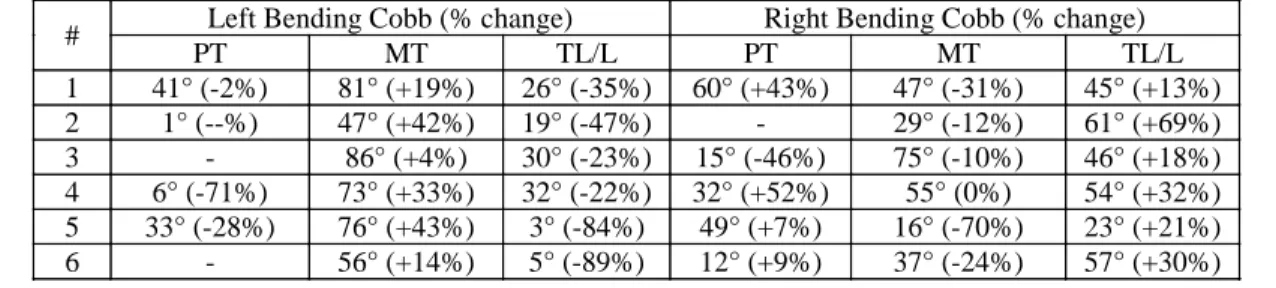
Table 3.3 (A1T3): Lateral bending Cobb angles and percentage change relative to standing position ... 59
Table 3.4 (A1T4): Average changes in spinal geometry due to prone positioning while varying patient and surgical frame parameters (standard deviations in brackets) ... 60 Table 3.5 (A2T1): Subject Data ... 83 Table 3.6 (A2T2): Comparison of simulations and experimentally measured results (all values in degrees). Values in parenthesis are those obtained after initial strain optimization ... 84 Table 3.7 (A3T1): Subject data and spinal geometries in the neutral and sternum lifted positions ... 96 Table 3.8 (A3T2): Apical spinal geometries in the neutral (N) and lifted (L) sternum positions ... 97 Table 3.9 (A3T3): Average (min-max) interface pressure measurements for all subjects in the neutral and raised positions ... 100 Table 3.10 (A4T1): Patient and lateral bending data ... 116 Table 3.11 (A4T2): Impact of lateral leg displacement (CV = convexity and CC = concavity) ... 117 Table 3.12 (A4T3): Impact of pelvic torsion ... 119 Table 4.1 (A5T1): Spinal geometry following optimization of individual parameters on the MFPF (distances in mm; angles in degrees). ... 142
Table 4.2 (A5T2): MFPF configuration for optimization of individual spinal geometrical parameters along with
significance of feature ability to manipulate spinal geometry (* for p < 0.05 and † for most influential MFPF feature) (TVD and TLD values in cm; HFE, LLD, and PTT values in degrees). ... 143 Table 4.2 (A5T3): Spinal geometry a) and combined surgical positions b) in the globally optimized position using two different cost functions (Φ1 and Φ2) over three example cases (W = geometrical parameter weighting; GD = geometrical parameter desired value; GI = geometrical parameter initial value). ... 144 Table A1.1: Validation of the relationship between hip flexion and loss of lumbar lordosis ... 174 Table A3.1: Dermis / Hypodermis Thicknesses ... 185
LIST OF FIGURES
Figure 1.1: Human spine ... 3 Figure 1.2: Ligaments of the spine ... 4 Figure 1.3: The pelvis ... 5 Figure 1.4: The hip joint ... 5 Figure 1.5: The hamstrings ... 6 Figure 1.6: The femur ... 7 Figure 1.7: The knee joint ... 7 Figure 1.8: The ribcage ... 8 Figure 1.9: Cartesian co-ordinate system oriented with respect to the spine ... 8 Figure 1.10: Cobb angle ... 9 Figure 1.11: Sagittal balance (left) and coronal balance (right) ... 10 Figure 1.12: The scoliotic spine ... 11 Figure 1.13: Posterior spinal instrumentation ... 12 Figure 1.14: Spondylolisthesis ... 14 Figure 1.15: Herniated disc ... 15 Figure 1.16: Lateral radiograph of kyphotic spine ... 16 Figure 1.17: Compressive fracture ... 17 Figure 1.18: The Relton-Hall frame ... 18 Figure 1.19: Andrews OSI Table ... 19 Figure 1.20: CAD drawing of the Dynamic Positioning Frame (DPF) ... 22 Figure 1.21: CAD drawing of the Multi-functional Positioning Frame (MFPF) ... 22 Figure 1.22: System simulation model ... 24 Figure 1.23: Example of a detailed FEM of an intervertebral disc ... 25
Figure 1.24: Example simplified global FEM of the spine ribcage and pelvis ... 26 Figure 1.25: Hybrid spine FEM ... 27 Figure 1.26: 3D Reconstruction Technique ... 28 Figure 1.27: Radiograph of a side bending test ... 29 Figure 2.1: Thesis organizational chart ... 33
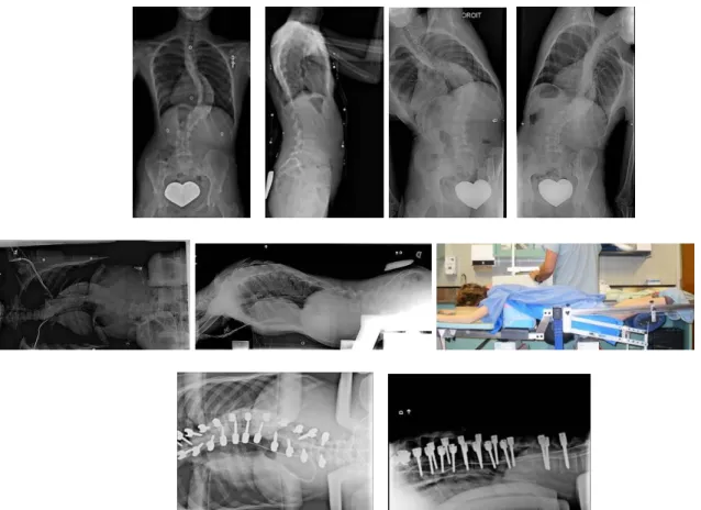
Figure 3.1 (A1F1): Representative radiographs of patient #1 from left to right, top row: PA standing, lateral standing, left and right standing lateral bending; middle row: PA and lateral on MFPF with picture of experimental setup; and
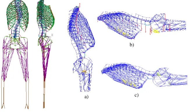
bottom row: PA and lateral on Relton-Hall frame ... 55 Figure 3.2 (A1F2): PA and Lateral Views of the developed FEM along with the three phases of the prone positioning simulations (patient #1): a) vertical application of forces equivalent to trunk segmental, head,
shoulder and upper limb weights; b) AP application of forces equivalent to trunk segment weights; c) pelvic tilt and thoracic vertical position adjustment ... 56
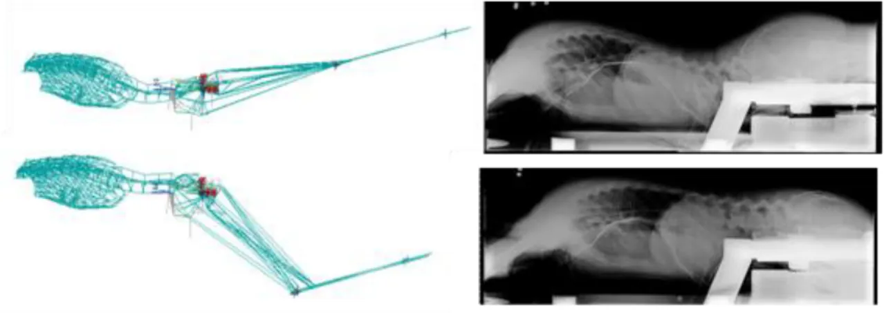
Figure 3.2 (A2F1): MFPF Leg Positioner; Extended (A) and flexed (B) positions ... 79 Figure 3.3 (A2F2): Coronal and sagittal views of the developed FEM ... 80 Figure 3.4 (A2F3): Comparison of simulations and experimentally measured results ... 81
Figure 3.5 (A2F4): Simulation of change in lordosis (A) and kyphosis (B) due to hip angle modulation ... 82
Figure 3.6 (A3F1): a) Experimental setup with a patient in the raised position; b) Details of the SVD cushion ... 95 Figure 3.7 (A3F2): Radiographs of subjects 1 to 6 in the a) neutral b) raised positions ... 98 Figure 3.8 (A3F4): Vertical and horizontal displacement of opto-electric sensors between radiographic positions for subject #4 ... 99
Figure 3.9 (A4F1): a) Lateral Leg Displacer (LLD) with subject; b-c) Pelvic Torsion Device (PTD) with and without subject. ... 115
Figure 3.10 (A4F2) : Radiographs of patients 1 to 6 and 11 in the neutral prone (top row) and laterally bent leg (bottom row) positions; arrow
indicated direction of lower limb displacement ... 118
Figure 3.11 (A4F3): Radiographs of patients 7 to 10 and 12 in the neutral prone (1st and second row) and twisted pelvis positions (3rd and fourth row); arrow
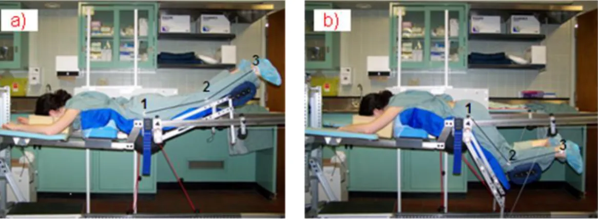
indicates direction of pelvic torsion ... 120 Figure 4.1 (A5F1): Multi-Functional Positioning Frame (MFPF) positioning features; a) lower limb positioned, b) thorax vertical displacer, c) lateral leg displacer, d) pelvic torsion device, and e) thorax lateral displacer. ... 139
Figure 4.2 (A5F2): FEMs; from left to right: main thoracic, double major, and triple major cases. ... 140
Figure 4.3 (A5F3): Limit phases of each positioning factor for the double major FEM; a) Thoracic Vertical Displacement (TVD),b) Thoracic Lateral
Displacement (TLD), c) Hip Flexion Extension (HFE), d) Lateral Limb Displacement (LLD), and e) Pelvic Transverse plane Torsion (PTT). For visualization purposed only the pelvis and spine are shown for the PTT case. ... 141 Figure 5.1: LLP CAD Representation ... 146 Figure 5.2: PTD CAD Representation ... 146 Figure 5.3: LTD CAD Representation ... 147
Figure 5.4: Scoliotic patient in the standing position (left) and combined lateral displaced torso and lower limb position (right) ... 148
Figure 5.5: Lateral radiographs of scoliotic patient in the standing position (left), maximum disc space (top right) and maximum sagittal balance and standing sagittal burves (bottom right) ... 149
Figure 6.1: Top view of patient in prone position on MFPF in the lateral bending position ... 156 Figure 6.2: Universal Feature Allowing Combined Lower Limb Positions ... 158 Figure 7.1: Volumetric FEM for the Study of Patient Positioning on the MFPF ... 162
Figure A1.1: Frontal and Lateral Views of the FEM developed ... 173 Figure A1.2: Impact of Lower Limb Positioning on a Newly Developed Surgical Frame ... 174 Figure A3.1: Experimental testing geometrical measurements with
corresponding VHP slices (only male CS slices shown). ... 185 Figure A3.2: Cross-section of the FEM thigh showing the different layers of soft tissue representation ... 186 Figure A3.3: Friction coefficient Experimental Setup ... 186 Figure A3.4: Comparison of interface pressures measured with a force sensing array (top) and simulated with the FEM (bottom) ... 187
LIST OF ANNEXES
ANNEX A THE RELATIONSHIP BETWEEN HIP FLEXION/
EXTENSION AND THE SAGITTAL CURVES OF THE SPINE...172 ANNEX B SPINAL GEOMETRY QUESTIONNAIRE...176 ANNEX C VOLUMETRIC FEM FOR THE STUDY OF PATIENT POSITIONING...182
INTRODUCTION
Patient positioning is an important step in spinal surgeries (Schonauer et al. 2004). Proper patient positioning should facilitate exposure, minimize bleeding, minimize chance of damage to vital structures, allow proper ventilation, avoid post-operative morbidity, and preserve sagittal alignment. Patient positioning also has an impact on spinal geometry. Studies have shown the relationship between hip flexion and loss of lumbar lordosis (Stephen et al. 1996 and Benfanti et al. 1997), prone positioning and the reduction in Cobb angles (Delorme et al. 2000) and sagittal curves (Jackson et al. 2005), back flexion/extension and degree of spondylolisthesis vertebral slip (Luk et al. 2003), and lateral force application on the deformity apex and the reduction in rib hump (Duke et al. 2002). It has been hypothesized that surgical effort (forces applied during instrumentation manoeuvres) can be reduced, and in some cases surgical results improved, if the spinal geometry is in the desired configuration for a given spinal surgery (Duke et al. 2005). Despite this, current operating tables used in spinal instrumentation/fusion procedures, such as the Relton-Hall and Orthopaedic Systems Inc. frames (Jackson, Wilson, and Andrews) allow limited spinal geometry modification through patient positioning.
A new multi-functional positioning frame (MFPF) has been developed at École Polytechnique and CHU Sainte-Justine (US Patent 7,234,180) (Canet 2008). It incorporates a mobile support for easy transportation, a static head rest, two movable arm rests, a leg positioning system that allows for hip movement from 60° flexion to 20° extension while maintaining the tibias at an angle of 20° above horizontal, a pelvic support cushion which is adjustable in height, thoracic cushions which are adjustable in height and horizontal direction, and a sternum vertical displacer which can rise 15 cm above the neutral plane established by linking the femoral heads and C7. Spine surgeries that are envisioned to utilize the MFPF are: scoliosis, spondylolisthesis, hyper-kyphosis, degenerative and herniated discs, and spinal trauma.
Finite element models (FEMs) allow for detailed analysis on displacement, stress, strain, and reaction forces to be computed by breaking down solids into finer simplified pieces known as elements which are interconnected by nodes. They have been used for several studies related to the spine such as the study of surgical techniques (Lafage et al. 2004; Grealou et al. 2002),
pathology development and progression (Villemure et al. 2004; Lin et al. 2010), brace treatment (Clin et al. 2007), etc. One previous finite element model was used to investigate the impact of surgical positioning on the geometry of the spine (Duke et al. 2005, 2008). This wireframe model contains 2974 elements and 1440 nodes. Patient specific 3D geometry of the spine, pelvis, and ribcage was obtained using a bi-planar reconstruction technique (Delorme et al. 2003). Material properties were obtained from literature and personalized using side bending radiographs (Petit et al. 2004). Interface with the surgical frame was represented by the application of nodal displacements and forces. Firstly, the model was used to simulate prone patient positioning on a surgical frame then to study the impact of different positioning parameters: pelvic incidence (+/-15°), chest cushion location (under ribs 3-6 or 6-9), chest cushion height (0 and 3.5 cm), and lateral corrective forces between 10-150 N on various spinal geometry parameters including their optimization. So far, this model was not used to study the impact of lower limb positioning, investigate new surgical positions or to optimize patient positions for different stages of surgeries.
The general objective of this thesis is to use a combination of finite element modelling and experimental testing to study how surgical patient positioning impacts geometry of the spine and how this knowledge can be used in order to improve surgical interventions. The existing MFPF features were studied as well as some novel features requiring the development of surgical frame accessory prototypes.
This thesis is composed of 5 scientific papers and is organized in 7 chapters. The 1st chapter contains a review of literature and relevant knowledge on spinal pathologies, surgical positioning objectives, surgical frames, and biomechanical finite element models. The 2nd chapter presents the objectives and the hypotheses of the project. The 3rd chapter presents individual studies in the form of scientific papers 1 through 4. The 4th chapter presents the optimization study in the form of scientific paper 5. The 5th chapter details the design of the new surgical positioning features developed. The 6th chapter links the previous chapters providing an overall discussion and the final chapter provides the study conclusions and recommendations.
CHAPTER 1
REVIEW OF LITERATURE
This review of literature covers the following topics: (1.1) functional and descriptive anatomy of the spine, thoracic cage, pelvis, and adjacent members, (1.2) spinal pathologies and their associated operations, and (1.3) modelling of the human trunk.
1.1 Functional and descriptive anatomy of the spine, thoracic cage, pelvis,
and lower limbs
The human spine (figure 1.1) is composed of vertebrae, discs, ligaments, and muscles. The vertebrae can be thought of as a chain of blocks stacked one on top of the other connected by inter-vertebral discs acting as hinges. Ligaments connect the blocks providing stability. Muscles also provide stability as well as the forces required for movement.
Figure 1.1: Human spine (consulted on October 13th 2010, obtained from http://en.wikipedia.org/wiki/File:Spinal_column_curvature.png)
The spine is composed of 33 vertebrae broken down into 5 categories. There are 7 cervical, 12 thoracic, 5 lumbar, 5 sacral (often fused into one), and 4 coccygeal (often fused into one). Vertebrae categorically vary in size and shape depending on their functionality but share many similar characteristics.
Intervertebral discs (figure 1.2) are the flexible members connecting vertebrae that allow motion and absorb shock. While each individual disc has limited flexibility, their combined effect allows for the back‟s large range of motion. They represent one fourth of the total spinal column‟s length and are composed of an annulus fibrosus surrounding a nucleus pulposus.
Ligaments (figure 2) serve as supporting structures and help stabilize the spine while protecting against excessive movement in any one direction. The spinal vertebrae are held together by two types of ligaments, the intrasegmental ligaments hold the individual vertebrae together and the intersegmental ligaments that hold many vertebrae together.
Figure 1.2: Ligaments of the spine (Stewart G. Eidelson. Save Your Aching Back and Neck, A Patient's Guide Second Edition, SYA Press, Inc. 2002)
A motion segment of the human spine is defined as two or more adjacent vertebrae, including the intervertebral disk between them, and the ligaments that bind them together.
Also of note are the costovertebral and zygapophyseal joints. The costovertebral joints are those forming articulations between a given rib and the spine, they include costotransverse joints and joints of rib heads. Costovertebral joints of the head of the rib are the articulations between the head of the ribs and the vertebral bodies. The costotransverse joints are the articulations on each side of the spinal column of a given thoracic rib with the transverse process of its corresponding thoracic vertebra. Zygapophyseal joints (aka facet joints) are the joints that occur between facets of the interior and superior articular processes of adjacent vertebra.
The pelvis (figure 1.3) is composed of three bones: the ilium, ischium, and pubis, which become fused together with age. It is joined to the sacrum by ligaments and provides socket joints for the hips. There are marked differences between the male and female pelvises, with characteristics of the female pelvis being better suited for childbirth. The pelvis plays a protective
role for digestive and reproductive organs and is an important load-bearing part of the skeletal system.
Figure 1.3: The pelvis (Consulted on October 11th 2010, obtained from http://media.photobucket.com/image/pelvis/danielgalvan05/untitled.jpg?o=31)
The hip joint (figure 1.4) is the ball and socket synovial joint between the cup-like acetabulum of the pelvis and the rounded head of the femur. Its primary function is to support the weight of the body in static and dynamic postures. Both surfaces of the joint are covered with a strong lubricated layer of articular hyaline cartilage. A fibrocartilaginous rim called the labrum grips the femoral head and secures it in the acetabulum. A capsule attached proximally to the periphery of the acetabulum covers the femoral head and attaches to the base of the neck and limits the hip range of motion.
Figure 1.4: The hip joint (Anatomy of the Human Body by H. Gray, 1918, Philadelphia: Lea & Febiger. Consulted on October 11th 2010, obtained from http://www.bartleby.com/107/92.html)
Three principle ligaments reinforce the hip joint: the iliofemoral ligament attaches the pelvis to the femur, the pubofemoral ligament attaches across the front of the joint from the pubis to the femur, and the ischiofemoral ligament attaches the ischial part of the acetabular rim to the femur.
There are five muscle groups that allow movement at the hip joint: flexor group (iliopsoas composed of the iliacus and psoas major), extensor group (hamstrings), lateral rotator group, adductor group, and abductor group (figure 1.5). The muscles have origins on the pelvis and insertions on the lower limbs.
Figure 1.5: The hamstrings (Anatomy of the Human Body by H. Gray, 1918, Philadelphia: Lea & Febiger. Consulted on October 11th 2010, obtained from http://www.bartleby.com/107/128.html) The femur (figure 1.6) is the longest, strongest and most voluminous bone of the human body forming part of the hip and knee. The proximal end of the femur consists of the head which is linked to its body by the neck at an angle of approximately 125o and the greater and lesser trochanter which serve as muscle attachment points. The body of the femur has several attachment points for muscles such as the linea aspera for the biceps femoris and the gluteal tuberosity for the gluteus maximus.
Figure 1.6: The femur (Anatomy of the Human Body by H. Gray, 1918, Philadelphia: Lea & Febiger. Consulted on October 11th 2010, obtained from http://www.bartleby.com/107/59.html)
The femur is linked to the tibia and fibula via the knee (figure 1.7), a pivotal hinge joint whose articular bodies are the lateral and medial condyles.
Figure 1.7: The knee joint (obtained on October 11th 2010 from http://commons.wikimedia.org/wiki/File:Knee_diagram.png)
The joint itself is bathed in synovial fluid which is contained inside the synovial membrane called the joint capsule and is surrounded by ligaments which add stability by limiting movement. The tibia and fibula are linked to each other by an interosseous membrane and their proximal portions serve as insertion points for several hip joint muscles including the hamstrings.
A typical ribcage (figure 1.8) consists of 12 pairs of ribs. They are attached posteriorly to the thoracic vertebrae at dedicated facet locations. The first 7 pairs, known as true ribs, are connected anteriorly to the sternum, pairs 8 through 10, known as false ribs, are connected
anteriorly to the cartilaginous portion of the rib above it, and the 11th and 12th pair, known as floating ribs, are not attached anteriorly. Due to their connection to the ribcage, the thoracic vertebrae are limited in their range of motion. The spacing between successive ribs, known as intercostals spacing, contains muscle, nerves, and arteries. The rib cage is elastic, which allows for expansion and contraction during breathing. Its primary function is the protection of the lungs and heart.
Figure 1.8: The ribcage (obtained on October 11th 2010 from http://commons.wikimedia.org/wiki/File:Rib_cage.gif)
1.1.1 Quantification of spinal geometry
There exist several tools that are used in order to describe the geometry of the spine. The ones presented here will be used in subsequent sections. First a body oriented coordinate system defines planes of interest as well as the orientation of the x, y, and z axes (figure 1.9).
Figure 1.9: Cartesian co-ordinate system oriented with respect to the spine (Obtained on October 11th 2010 from http://en.wikipedia.org/wiki/File:Human_anatomy_planes.svg)
The Cobb angle (figure 1.10) can be used to define the curvature for a specified segment of the spine in the coronal plane.
Z
X Y
Figure 1.10: Cobb angle (obtained on October 11th 2010 from http://en.wikipedia.org/wiki/File:Scoliosis_cobb.gif)
A line is drawn along the upper endplate of the proximal end vertebra and along the lower endplate of the distal end vertebra of a given segment; the angle of intersection of these two lines is defined as the Cobb angle. The same technique could be used to measure sagittal curves (kyphosis, lordosis).
The spine of a healthy human is generally straight when viewed on the coronal plane (Schultz 1991). In the sagittal plane, there are natural occurring curves as can be seen in figure 1. These curves serve to balance weight, absorb shock, provide protection, and help the body maintain an upright posture. A curve with an anterior facing apex is defined as lodortic, while a curve with a posterior facing apex as kyphotic. The extent to which the spine is curved in the sagittal plane, measured using the Cobb angle, varies among individuals and is age dependent. The thoracic region (top of T1 to bottom of T12) of a mature spine has a mean kyphosis of 38.5° (SD 8.1°) and the lumbar region (top of L1 to bottom of L5) of a mature spine has a mean lordosis of 56.6° (SD 9.1°) (Voutsinas 1986).
Sagittal spinal balance is defined as the vertical alignment of the midpoint of the C7 or T1 body with the posterior superior corner of the sacrum in the sagittal plane (figure 1.11).
Figure 1.11: Sagittal balance (left) and coronal balance (right) (obtained on October 11th from www.srs.org/professionals/glossary/glossary.php)
Coronal balance is defined as the vertical alignment of the midpoint of the C7 or T1 body with the mid-point of the sacrum in the coronal plane. Spines with a sagittal balance < 40 mm and coronal balance < 25 mm are considered to be normal (Heart 2007) and even a mild imbalance can have detrimental effects (Glassman 2005).
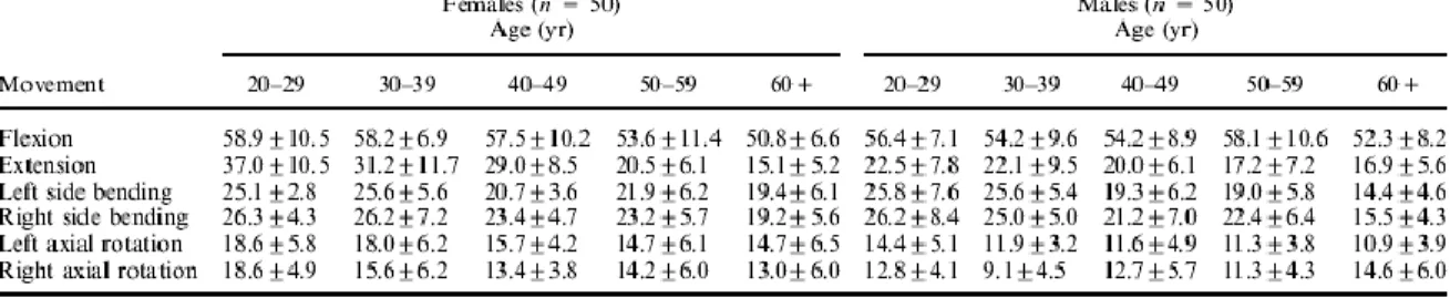
The spine is generally described as having 6 degrees of motion: flexion, extension, left side bending, right side bending, left axial rotation, and right axial rotation. Van Herp et al. (2000) studied the range of motion of the human spine using x-rays and goniometry with the results summarized in Table 1.1.
Table 1.1: Range of motion of the human trunk (Modified from Van Herp 2000)
The description of the spine given thus far has been applicable for the normal standing position. There are several factors that can influence spinal geometry including trunk and associated member movement such as left/right lateral as well as anterior/posterior movements of the ribcage (Harrison 1999, 2002), anterior/posterior pelvic tilt (Delisle 1997), leg position (Cho