HAL Id: hal-02467848
https://hal.archives-ouvertes.fr/hal-02467848
Submitted on 5 Feb 2020
HAL is a multi-disciplinary open access
archive for the deposit and dissemination of
sci-entific research documents, whether they are
pub-lished or not. The documents may come from
teaching and research institutions in France or
abroad, or from public or private research centers.
L’archive ouverte pluridisciplinaire HAL, est
destinée au dépôt et à la diffusion de documents
scientifiques de niveau recherche, publiés ou non,
émanant des établissements d’enseignement et de
recherche français ou étrangers, des laboratoires
publics ou privés.
Simplified stress analysis of multilayered adhesively
bonded structures
Kübra Sekmen, Eric Paroissien, Frederic Lachaud
To cite this version:
Kübra Sekmen, Eric Paroissien, Frederic Lachaud. Simplified stress analysis of multilayered
adhe-sively bonded structures. International Journal of Adhesion and Adhesives, Elsevier, 2020, 97, pp.0.
�10.1016/j.ijadhadh.2019.102497�. �hal-02467848�
an author's
https://oatao.univ-toulouse.fr/25080
https://doi.org/10.1016/j.ijadhadh.2019.102497
Sekmen, Kübra and Paroissien, Eric and Lachaud, Frédéric Simplified stress analysis of multilayered adhesively
bonded structures. ( In Press: 2020) International Journal of Adhesion and Adhesives, 97. ISSN 0143-7496
Simplified stress analysis of multilayered adhesively bonded structures
Kubra Sekmen, Eric Paroissien
*, Fr�ed�eric Lachaud
Institut Cl�ement Ader (ICA), Universit�e de Toulouse, ISAE-SUPAERO, INSA, IMT MINES ALBI, UTIII, CNRS, 3 Rue Caroline Aigle, 31400, Toulouse, France
Keywords:
Multilayered bonded joint Semi-analytical resolution Macro-element
Finite element stress analysis Stress analysis
Stress distribution Linear material adhesive
A B S T R A C T
Bolting technologies have been commonly used to assemble structural members in order to carry loads. However, the main drawback of these joints is the local reduction of the strength-to-stress ratio. Compared to the bolted joints, adhesive bonding technology allows for the increase of static and fatigue strength while reducing the weight. The Finite Element (FE) method is able to address the stress analysis of bonded joints. Nevertheless, analyses based on FE models are computationally expensive. Therefore, it is profitable to develop new simplified approaches enabling extensive parametric studies. A semi-analytical technique was developed to model the joints based on the formulation of 4-node special elements, termed macro-elements, which is able to simulate an entire bonded overlap at low computational costs. In this paper, a multilayered bonded-bars and a multilayered bonded-beams macro-elements are derived from bonded-bar and bonded-beam macro-elements. 1D-bar and 1D- beam simplified stress analyses of such multilayered joints are presented in order to predict the adhesive stress distributions along the overlap. For validation purpose, the results obtained by the simplified 1D-bar and 1D- beam model are compared with the results predicted by 1D-FE models. Good agreements are shown. Finally, the parametric studies are performed in order to understand the mechanical behavior of multilayered adhesively bonded structures. This presented simplified stress analysis can be used to deduce the sizing guidelines as a consequence of these parametric studies.
1. Introduction
In recent years, there has been an increasing interest in the adhe-sively bonded technology for the design of lightweight structures. Compared to the conventional methods such as riveting or bolting, bonding offers better mechanical properties in terms of stiffness, static strength and fatigue strength when joining without damaging dissimilar materials such as metals and composites [1–4]. The Finite Element (FE) method is able to address the stress analysis of bonded joints. However, since analyses based on FE models are computationally expensive, it would be profitable to develop new simplified approaches enabling extensive parametric studies. Numerous studies have attempted to perform simplified stress analysis and provided accurate predictions [5–7]. In 1938, Volkersen published the first stress analysis including the deformation of the adherends by the development of a shear lag model [8]. In 1944, Goland and Reissner developed the analysis of Volkersen by the first closed-form solution of adhesive stress distribu-tions along the overlap for simply supported balanced joint made of adherend undergoing cylindrically bending [9]. The sandwich-type analysis concept was then employed by other researchers in order to
improve this initial model considering different local equilibriums, different constitutive behaviors and various geometries [10–18]. The second and third authors of the present paper and their co-workers have been working on the development of the macro-element (ME) technique for the simplified stress analysis of bonded, bolted and hybrid (bon-ded/bolted) joints [19–29]. The ME technique is a semi-analytical res-olution method inspired by the FE method and is developed to solve the system of differential equations considering the restrictions such as dissimilar adherends, various boundary conditions, and nonlinear ad-hesive material properties. A ME is then an element which includes physical properties of both adhesive layers and adherends as illustrated in Fig. 1. A number of researchers investigated the mechanism of load transfer in multilayered structures by using shear-lag theory. Nairn and Mendels proposed an optimal shear-lag method for the stress problems of the 2D planar layered structures [30]. Jiang and Peters derived a shear-lag model for 3D multilayered structures whose properties vary along the cross-section through the extension of Nairn and Mendels’ study such as smart structures with embedded sensors and actuators [31]. Viet et al. also provided a new analytical model to predict the interlaminar shear stress in adhesively bonded multilayered metal laminates for the purpose of modeling layers of piezoelectric materials
* Corresponding author.
E-mail address: eric.paroissien@isae-supaero.fr (E. Paroissien).
on the future energy harvesting application [32]. Recently, Pham et al. developed a FE formulation for the analysis of multilayered beams based on the principle of stationary complementary strain energy which differs from previous studies [33].
Literature reviews have indicated that plenty of models of the adhesively bonded joints have been developed to size simple configu-rations. Although the effectiveness of the adhesively bonded joint is widely known, the stress analysis and sizing methodologies of multi-layered structures have not been extensively studied. Since studies on the stress analysis and sizing of the multilayered structures are rare to find in literature, the semi-analytical analysis in applying well-known schemes and parametric studies are performed in this work.
The objectives of the present paper are to perform the simplified stress analysis of the multilayered adhesively bonded joint under the static loading and to conduct parametric studies in order to understand their effects on the mechanical behavior of such joints. First of all, simplified stress analyses based on ME technique in 1D-bar and 1D-beam framework explained. The detailed mathematical description of semi- analytical resolution is provided. Then, 1D-FE models are presented and used to validate 1D-ME models through dedicated convergence studies. Finally, the parametric studies are performed in order to un-derstand the mechanical behavior of such joints. The computations were performed thanks to house-made computer programs developed in MATLAB. Codes are provided as supplementary materials [34].
2. Description of simplified stress analyses of multilayered bonded joints
2.1. Overview of the macro-element technique and application
The simplified linear elastic method is originally developed for the hybrid (bolted/bonded) joints [21,22]. The ME technique is a mathe-matical procedure inspired by the FE method. When the ME technique
takes the shape of solutions of the governing ordinary differential equations (ODEs) systems, it differs from the common FE method because of the fact that the interpolation functions are not assumed. This method allows for the resolution of the system of ODEs, which are derived from the constitutive equations of the adhesives and adherends and local equilibrium equations, under a less restricted application field of the simplifying hypotheses in terms of the geometry, material behavior, kinematics, boundary conditions and applied loads. A direct outcome is that only one ME is sufficient to mesh a complete bonded overlap. The main work is the formulation of the elementary stiffness matrix of the multilayered bonded elements. A multilayered bonded-bars and a multilayered bonded-beams MEs are derived based on the formulation of 4-nodes bonded-bar and bonded-beam elements. In this work, the formulation is based on the exponential matrix to solve the system of first order ODEs and then to derive the elementary stiffness matrix of these ODEs. As a result, in order to assess the adherend dis-placements, internal forces and adhesive stresses, an entire bonded overlap is meshed using dedicated MEs. According to FE rules, the global stiffness matrix of the complete structure is assembled from the elementary stiffness matrices of the macro-elements. Boundary condi-tions and prescribed loadings are applied through the Augmented Lagrangian Method [34]. Based on the minimization of the total po-tential energy, the linear system is solved in order to compute the
Nomenclature and units
A matrix of the system of 1st order ODE coefficients
Ai extensional stiffness (N) of adherend i
Bi extensional and bending coupling stiffness (N.mm) of
adherend i
Di bending stiffness (N.mm2) of adherend i Ea,i adhesive Young’s modulus (MPa) of adhesive i Ei adherend Young’s modulus (MPa) of adherend i Fe vector of nodal forces
Gi adhesive shear modulus (MPa) of the adhesive i
Ke elementary stiffness matrix of multilayered macro-element
L length (mm) of bonded overlap
Me matrix of nodal displacements
Mi bending moment (N.mm) in the adherend i around the z-
direction
Ne matrix of nodal forces
Ni normal force (N) in the adherend i in the x-direction
P element nodal displacement vector
Si adhesive peel stress (MPa) in the adhesive i in the y-
direction
Smax maximal adhesive peel stress (MPa)
Ti adhesive shear stress (MPa) in the adhesive i in the x-
direction
Tmax maximal adhesive shear stress (MPa)
Ue vector of nodal displacements
Vi shear force (N) in the adherend i in the y-direction Z vector of normal forces and displacements for semi-
analytical resolution
b width (mm) of the adherends
ei thickness (mm) of adherend i f magnitude of applied tensile force (N)
hi half thickness (mm) of adherend i
kI adhesive elastic stiffness (MPa/mm) in the peel kII adhesive elastic stiffness (MPa/mm) in shear ku spring element stiffness (N/mm) along the x-axis kv spring element stiffness (N/mm) along the y-axis nBE number of bar or beam elements
nME number of macro-elements
ti thickness (mm) of the adhesive layer i
tiFE thickness (mm) of the adhesive layer used in the FE model ui displacement (mm) of adherend iin the xdirection vi displacement (mm) of adherend iin the ydirection
Δi overlap length (mm) of a macro-element θi bending angle (rad) of the adherend iaround the
z-direction
φA vector of normal forces and displacements at each
extremity
φF vector of normal forces each extremity φU vector of displacements at each extremity
νa;i Poisson’s ratio of the adhesive layers
ðx;y;zÞ global reference system of axes
FE Finite Element ME macro-element
ODE ordinary differential equation
displacements and forces in the adherends as well as the adhesive shear and peel stresses. Finally, different mechanical loading could be easily taken into account.
2.2. D-bar and 1D-beam element model 2.2.1. Bonded-bars element: 1D-bar kinematics
The following hypotheses were taken (i) the adherends are linear elastic materials simulated as 1D-bars, (ii) the adhesive layer is simu-lated by an infinite number of linear elastic shear springs linking the adherends (iii) the thickness of the adhesive layer is constant along the overlap, and (iv) the adhesive stresses are constant through the thickness [8]. As a consequence of the simplified hypotheses, the following ar-guments are taken into consideration (i) only normal forces and only longitudinal displacements are considered in the adherend, (ii) the ad-hesive normal stress cannot be represented because any normal force is
not applied to the adhesive layer, and (iii) it is assumed that all the adhesive stress components disappear except the in-plane shear. The ME is formed of a total of Padherends which are linked by P 1interfaces representing adhesive layers. The nomenclature of ME for a multilay-ered adhesively bonded joint is described as shown in Fig. 2. The nodes of the ME are located on the neutral axis of each layer. Each layer has 2 nodes which are located on the starting and end of the layers. Thus, a ME including Players has 2Pnodes in total. Within the scope of 1D-bar ki-nematics, there is 1�of freedom which is longitudinal displacement. The
total number of degrees of freedom is computed by multiplying a total of nodes with a degree of freedom per nodes. As a result, 1 ME of Players includes a total of 2Pdegrees of freedom. In this model, nodes at the interfaces are not modeled. The modeling of each layer as a bar allows for the computation of the longitudinal displacements, normal forces, normal stresses, and strains.
The local equilibrium of the adherends belongs to the Volkersen type. Based on the free body diagram of infinitesimal pieces included between xand x þ dxof Padherends in the overlap region as presented in
Fig. 3, one equation is obtained for each layer. As a result, a total of
Pequations are obtained for Players.
The local equilibrium equations are given for 1st, ithð2 � i � P 1Þ
and Pthadherend: 8 > > > > > > > < > > > > > > > : dN1 dx þT1b ¼ 0 dNi dx ðTi 1 TiÞb ¼ 0 dNP dx TP 1b ¼ 0 (1)
where Niis the normal force in the adherend i, bthe width of the
adherends and Tithe adhesive shear stress.
One constitutive equation for the adhesive shear stress describes each interface behavior. Then, a total of P 1equations are involved. For 1 � i � P 1, the linear elastic material behavior provides the constitutive equations of interfaces are below:
Fig. 2. Representation of the nomenclature for the ME of multilayered joint.
Ti¼
Giðuiþ1 uiÞ
ti (2)
where tiis the thickness of adhesive layer i, Giis the shear modulus of
adhesive layer i, uiis the normal displacement of points located at the
abscissa xon the neutral line of adherend ibefore deformation. The constitutive equations for the adherends (1 � i � P) are provided by: Ni¼Eibei dui dx ⇒ dui dx ¼ 1 Eibei Ni (3)
where Eiis Young’s modulus of the adherend iand eithe thickness of the
adherend i.
The ODEs are organized in order to get the expression for displace-ments and then for internal forces by the resolution. Substituting Eq. (2)
into Eq. (1), the following local equilibrium equations are obtained: 8 > > > > > > > > < > > > > > > > > : dN1 dx ¼b G1 t1 u1 b G1 t1 u2 dNi dx ¼ b Gi 1 ti 1 ui 1þb � Gi 1 ti 1 þGi ti � ui b Gi ti uiþ1 dNP dx ¼ b GP 1 tP 1 uP 1þb GP 1 tP 1 uP (4)
2.2.2. Bonded-beams element: 1D-beam kinematics
The set of simplifying hypotheses are: (i) the adherends are simulated by linear elastic 1D Euler-Bernoulli laminated beams, (ii) the adhesive layer is simulated by an infinite number of elastic shear and transverse springs linking the adherends, (iii) the thickness of the adhesive layer is constant along the overlap, and (iv) the adhesive stresses are constant through the thickness [9]. As a consequence of the simplified hypothesis, the following arguments are taken into consideration (i) normal forces, shear forces and bending moments are considered in the adherends, (ii) longitudinal displacements, deflections and bending angles are considered in the adherends, (iii) adhesive shear and peel stresses are represented in the adherends, and (iv) the adhesive longitudinal stresses are neglected. Similar to 1D-bar model, the ME is formed by Padherends and P
1interfaces. The nomenclature of ME for a multilayered adhesively bonded joint is presented as given in Fig. 2. Within the scope of 1D-beam kinematics, there are 3�of freedom which are axial displacement, vertical
displacement, and rotation. The total number of degrees of freedom is computed by multiplying a total of nodes with a degree of freedom per nodes. As a result, one ME of Players includes a total of 6Pdegrees of freedom. Similar to 1D-bar model, nodes at the interfaces are not modeled in 1D-beam model. The local equilibrium of the adherends belongs to Goland and Reissner type. Based on the free body diagram of infinitesimal pieces included between xand x þ dxof Padherends in the overlap region as shown in Fig. 4, three equations are obtained for each layer. As a result, a total of 3Pequations are obtained for Players. The half thickness of the adherend iare termed hi:
hi¼
ei
2; i ¼ 1; …; P (5)
The local equilibrium equations are given for 1st, ithð2 � i � P 1Þ and Pthadherend: 8 > > > > > > > > > > > > > > > > > > > > > > > > > > > > > > > > > > > > < > > > > > > > > > > > > > > > > > > > > > > > > > > > > > > > > > > > > : dN1 dx þT1b ¼ 0 dV1 dx S1b ¼ 0 dM1 dx þV1þT1bh1¼0 dNi dx ðTi 1 TiÞb ¼ 0 dVi dxþ ðSi 1 SiÞb ¼ 0 dMi dx þViþ ðTi 1þTiÞbhi¼0 dNP dx TP 1b ¼ 0 dVP dx þSP 1b ¼ 0 dMP dx þVPþTP 1bhP¼0 (6)
where Niis the normal force in the adherend i, Vithe shear force in the
adherend i, Mibending moment in the adherend i, bthe width of the
adherend, Tithe adhesive shear stress in the adhesive iand Sithe adhesive
peel stress in the adhesive i.
Two constitutive equations regarding the adhesive stresses describe
each interface behavior. Then, a total of 2ðP 1Þequations are involved. For 1 � i � P 1, the linear elastic material behavior provides the constitutive equation of interfaces as functions of adherends displace-ments are below:
�
Si¼kI;iðwi wiþ1Þ
Ti¼kII;iðuiþ1 ui hiþ1θiþ1 hiθiÞ (7) where kI;i ¼Eta;i
iis adhesive elastic stiffness in the peel, kII;i ¼
Gi
tiadhesive
elastic stiffness in the shear, tithe thickness of the adhesive i, Ea;ithe
elastic modulus of the adhesive i, Githe shear modulus of the adhesive i, uithe axial displacement of the adherend i, withe deflection of the
adherend iand θithe bending angle of the adherend i.
The constitutive equations for the adherends ð1 � i � PÞare provided by: 8 > > > > > > > < > > > > > > > : Ni¼Ai dui dx Bi dθi dx⇒ dui dx¼ Di Ωi Niþ Bi Ωi Mi Mi¼ Bi dui dxþDi dθi dx⇒ dθi dx ¼ Bi Ωi Niþ Ai Ωi Mi θi¼ dwi dx (8)
where Aiis the extensional stiffness of the adherend i, Dithe bending
stiffness of the adherend i, Bithe extensional and bending coupling
stiffness of the adherend iand Ωi ¼ AiDi–BiBiis different from zero for i ¼ 1;…;P.
Substituting Eq. (7) into Eq. (6), the following local equilibrium equations are obtained:
2.3. Semi-analytical resolution
The formulation of elementary stiffness matrices of the multilayered bonded-bars element and the multilayered bonded-beams element is derived from the linear relationship between the vector of nodal forces
Feand the vector of the nodal displacements Ue. The elementary stiffness
matrices for multilayered bonded-bars element and multilayered bonded-beams element Keare provided in Eqs. (10) and (11),
respectively. 0 B B B B B @ N1ð0Þ Nið0Þ Npð0Þ N1ðΔÞ NiðΔÞ NPðΔÞ 1 C C C C C A ¼Ke 0 B B B B B @ u1ð0Þ uið0Þ upð0Þ u1ðΔÞ uiðΔÞ uPðΔÞ 1 C C C C C A ⇔ Fe¼KeUe (10)
where Δis the length of the ME.
In the case of 1D-bar and 1D-beam kinematics, the semi-analytical resolution is carried out using the ME technique in order to determine the elementary stiffness matrices.
2.4. Multilayered bonded-bars element
The system of first order ODEs, which are derived from Eqs. (3) and (4) can be written under a matrix shape such as:
� dZ dx � ¼ ½A�fZg (12) where Z ¼ ðN1…Ni…NPu1…ui…uPÞT.
The solution of the system is under the shape of the exponential of the matrix as shown in Eq. (13).
Z ¼ expmðAxÞ:Z0 (13)
where fZ0gis the vector constant.
The ME of the multilayered bonded-bars is modeled as illustrated in
Fig. 5. From the first layer to the last layer P, all layers are assembled one under the other. Node numbering is provided as layer by layer in order
to obtain one multilayered ME. The numbering of degrees of freedom of the ME is started with the first node of each layer, and it is done from the top layer to the bottom layer. Then, after reaching the first node of the last layer, numbering proceeds from the second nodes of the first layer to the last layer. One multilayered bonded-bars element has a total of 2Pnodes, 2Px1degrees of freedom, P 1adhesive layers, and
Padherends.
The elementary stiffness matrix of a multilayered bonded-bars element has to be determined. The implementation of the elementary stiffness matrix is carried out by MATLAB software. The MATLAB pro-vides the possibility to compute the exponential of a matrix by means of the function “expm”. The following steps have been used to obtain the 8 > > > > > > > > > > > > > > > > > > > > > > > > > > > > > > > > > > > > < > > > > > > > > > > > > > > > > > > > > > > > > > > > > > > > > > > > > : dN1 dx ¼ bkII;1ðu2 u1 h2θ2 h1θ1Þ dV1 dx ¼bkI;1ðw1 w2Þ dM1 dx ¼ V1 bh1kII;1ðu2 u1 h2θ2 h1θ1Þ dNi
dx ¼bkII;i 1ðui ui 1 hiθi hi 1θi 1Þ bkII;iðuiþ1 ui hiþ1θiþ1 hiθiÞ dVi
dx ¼ bkI;i 1ðwi 1 wiÞ þbkI;iðwi wiþ1Þ dMi
dx ¼ Vi bhikII;i 1ðui ui 1 hiθi hi 1θi 1Þ bhikII;iðuiþ1 ui hiþ1θiþ1 hiθiÞ dNP dx ¼bkII;P 1ðuP uP 1 hPθP hP 1θP 1Þ dVP dx ¼ bkI;P 1ðwP 1 wPÞ dMP dx ¼ VP bhPkII;P 1ðuP uP 1 hPθP hP 1θP 1Þ (9)
multilayered bonded bar element stiffness matrix. Firstly, the boundary conditions at both extremities of the ME in x ¼ 0and x ¼ Δlead to the expressions of fundamental 6P x 6Pmatrices.
φAðx ¼ 0Þ ¼ EXPmðAx0Þ6PX6P (14)
φAðx ¼ ΔÞ ¼ EXPmðAxΔÞ6Px6P (15)
Each line of these matrices indicates each line of the vector ðN uÞTwhich is computed at each extremity in x ¼ 0and x ¼ ΔSecondly, 3P x 6Pmatrices referring to displacements Uonly and forces Fonly at each extremity are computed.
φUð0; ΔÞ ¼ � EXPmðAx0Þi¼4P:6P;j¼1:6P EXPmðAxΔÞi¼4P:6P;j¼1:6P � ðu1ð0Þ… uið0Þ… uPð0Þ u1ðΔÞ… uiðΔÞ… uPðΔÞÞT (16) φFð0; ΔÞ ¼ � EXPmðAx0Þi¼1P:3P;j¼1:6P EXPmðAxΔÞi¼1P:3P;j¼1:6P � ðN1ð0Þ… Nið0Þ… NPð0Þ N1ðΔÞ… NiðΔÞ… NPðΔÞÞT (17) Thirdly, 6P x 6Pmatrix Meof nodal displacements is reordered in the
base
ðu1ð0Þ u1ðΔÞ …uið0Þ uiðΔÞ …uPð0Þ uPðΔÞÞT
instead of ðu1ð0Þ… uið0Þ… uPð0Þ u1ðΔÞ…uiðΔÞ…uPðΔÞÞT. Me¼ � EXPmðAx0Þi¼4P:6P;j¼1:6P EXPmðAxΔÞi¼4P:6P;j¼1:6P � ðu1ð0Þ u1ðΔÞ …uið0Þ uiðΔÞ …uPð0Þ uPðΔÞÞT (18)
6P x 6Pmatrix Neof nodal forces is also reordered in the base
ð N1ð0Þ N1ðΔÞ … Nið0Þ NiðΔÞ … NPð0Þ NPðΔÞÞT
instead of ðN1ð0Þ… Nið0Þ… NPð0Þ N1ðΔÞ…NiðΔÞ…NPðΔÞÞT. Ne¼ � EXPmðAx0Þi¼4P:6P;j¼1:6P EXPmðAxΔÞi¼4P:6P;j¼1:6P � ð N1ð0Þ N1ðΔÞ … Nið0Þ NiðΔÞ … NPð0Þ NPðΔÞÞT (19) Finally, the stiffness matrix is then computed by the following
product of matrices.
½Ke� ¼ ½Ne�½Me� 1 (20)
2.4.1. Multilayered bonded-beams element
Similar to the multilayered bonded-bars element, the system of first order ODEs, which are derived from Eqs. (8) and (9), can be written under a matrix shape in Eq. (12) where Z ¼
ðN1…Ni…NPV1…Vi…VPu1…ui…uPw1…wi…wPθ1…θi…θPÞT. The solution of the system is under the shape of the exponential of the matrix as shown in Eq. (13). The ME of the multilayered bonded- beams is modeled as illustrated in Fig. 6. The elementary stiffness ma-trix of a multilayered bonded-beams element has to be determined. The following steps have been used to obtain the multilayered beam element stiffness matrix. First of all, the boundary conditions at both extremities of the ME in x ¼ 0and x ¼ Δlead to the expressions of fundamental 6P x 6Pmatrices.
φAðx ¼ 0Þ ¼ EXPmðAx0Þ6PX6P (21)
φAðx ¼ ΔÞ ¼ EXPmðAxΔÞ6Px6P (22)
Each line of these matrices indicates each line of the vector
ðN V M u w θÞTwhich is computed at each extremity in x ¼ 0and x ¼
ΔThen, 3P x 6Pmatrices referring to displacements Uonly and forces
Fonly at each extremity are computed. φUð0; ΔÞ ¼ � EXPmðAx0Þi¼4P:6P;j¼1:6P EXPmðAxΔÞi¼4P:6P;j¼1:6P � ðu0w0θ0uΔwΔθΔÞT (23)
Fig. 7. Multilayered bonded joint for P ¼ 4with principle scheme of the ME. Table 1
Geometrical parameters of joint configuration.
Length of the overlap L 30 mm Width of the adherends b 1 mm Thickness of the adherends ei 2.5 mm
Thickness of the adhesives ti 0.11 mm
Table 2
Material parameters of the adherends and adhesives.
Young’s modulus of adherends Ei 70 GPa
Shear modulus of the adhesives Gi 100 MPa
Poisson’s ratio of the adhesives va;i 0.3
Young’s modulus of the adhesives Ea;i 266 MPa
Table 3
Mechanical analysis parameters.
Applied force f 100 N Number of adherend layers P 4
φFð0; ΔÞ ¼ � EXPmðAx0Þi¼1P:3P;j¼1:6P EXPmðAxΔÞi¼1P:3P;j¼1:6P � ðN0V0M0NΔVΔMΔÞT (24) After that, 6P x 6Pmatrix Meof nodal displacements is reordered in the
base ðu0uΔw0wΔθ0θΔÞTinstead of ðu0w0θ0uΔwΔθΔÞT.
Me¼ � EXPmðAx0Þi¼4P:6P;j¼1:6P EXPmðAxΔÞi¼4P:6P;j¼1:6P � ðu0uΔw0wΔθ0θΔÞT (25) 6P x 6Pmatrix Neof nodal forces is also reordered in the base
ð N0NΔ V0VΔ M0MΔÞTinstead of ðN0V0M0NΔVΔMΔÞT. Ne¼ � EXPmðAx0Þi¼4P:6P;j¼1:6P EXPmðAxΔÞi¼4P:6P;j¼1:6P � ð N0NΔ V0VΔ M0MΔÞT (26) Finally, the stiffness matrix is then computed by the following product of matrices.
½Ke� ¼ ½Ne�½Me� 1 (27)
3. Validation
For validation purpose, the relevance of 1D-bar model is assessed in order to understand if the method is well-implemented. Then, the pre-dictions obtained by the simplified 1D-bar and 1D-beam ME model are compared with the results predicted by 1D-FE models.
3.1. Nominal test case
In this paper, a clamped-free end multilayered joint subjected to in- plane tensile loading with a force f. This axial force is applied to the
Pthlayer at x ¼ Lwhere Lis the length of the overlap. The bonded overlap
is regularly meshed with nMEof multilayered bonded-bars and
multi-layered bonded-beams elements. The number of adherends is chosen
P ¼ 4in order to perform the stress analysis as given in Fig. 7 with the ME scheme. The material, geometrical and mechanical analysis pa-rameters are provided in Tables 1–3, respectively.
3.2. Description of the FE model
The FE models are designed considering the same hypotheses as ME models in order to justify the developed models [29]. This FE model is applied to a particular case in order to study the mechanical analysis of multilayered joints. 1D-FE models were developed by bar or beam ele-ments for the adherends and spring element for the adhesive layers. The nodes associated with the bar and beam elements are located at the actual neutral line of the adherend. The nodes associated with the spring elements are located at the actual interfaces of the adherends. Rigid body elements are used in order to link the nodes of the neutral lines to the nodes of the adherend interface for each adherends along the overlaps. A scheme of the 1D-FE model is presented in Fig. 8 including prescribed displacements and loading. It is possible to consider the geometrical effect of the adhesive thickness by assigning tiFE ¼ tiinstead
of tiFE ¼ 0. The bar and beam elements are based on third degree interpolating functions under the Euler-Bernoulli kinematics. The overlap length is regularly meshed by nBE. The stiffnesses of springs ku;iand kv;iare directly related to the mesh density along the overlap [35].
For a spring element located at an abscissa xalong the overlap, the stiffnesses are computed from the actual value of adhesive peel and shear modulus, the adhesive thicknesses ti, the width band the mesh
density L nBEsuch as: 8 > > > < > > > : kv;i¼mðxÞ L nBE bkI;i ku;i¼mðxÞ L nBE bkII;i (28) where mð0 < x < LÞ ¼ 1and mðx ¼ 0Þ ¼ mðx ¼ LÞ ¼1 2.
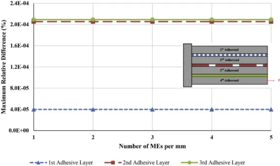
Fig. 9. Maximum relative difference between FE and ME adhesive peak shear stress predictions by 1D-bar model in terms of the number of MEs used per mm.
The FE models were developed in SAMCEF v171 FE code. All the details and convergence studies of the FE model are available Ref. [29]. In the present paper, a number of bar or beam elements is then chosen equal to 600 for L ¼ 30 mmleading to a mesh density of 20 elements per mm providing convergent results.
3.3. Validation of 1D-bar ME
Before mesh influence study, the relevance of 1D-bar model is assessed in terms of the symmetry of the stiffness matrix and model restriction by a single-lap joint which has the elementary stiffness matrix determined analytically [19,22]. Firstly, the symmetry of the elemen-tary stiffness matrix is checked by computing the relative difference
between each element of the matrix and the corresponding elements of its transpose. A maximal relative difference of 1.93 � 10 13% is
computed using the geometrical and mechanical properties provided in
Tables 1–3. Secondly, the model is restricted with the single-lap joint. The relative difference is computed 6.13 � 10 13% from the maximum
difference between the elements of the stiffness matrices of the ME model and analytical model provided in Refs. [19,22]. These small relative differences indicate that the model is well-implemented. Following this, the mesh influence study is studied with FE predictions in order to justify the ME model. Mesh refinement is carried out by a density of mesh per mm. 5 different tests are performed using 1, 2, 3, 4 and 5 MEs per mm. The maximal adhesive shear stresses Tmaxand
rela-tive differences between Tmaxpredicted by 1D-bar ME model and those
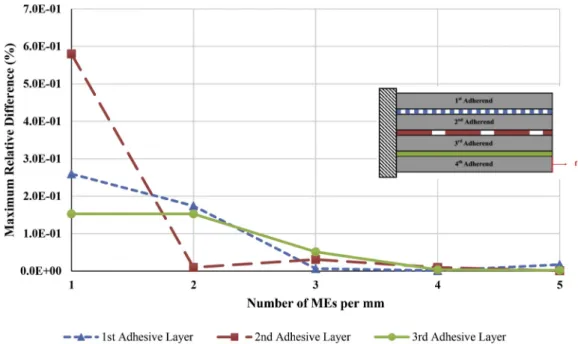
Fig. 11. Maximum relative difference between FE and ME adhesive peak peel stress predictions by 1D-beam model in terms of the number of MEs used per mm.
predicted by 1D-bar FE model are provided in Table A-1 and Table A-2
(Appendix A), respectively. It can be seen in Fig. 9 that as the number of MEs per mm increases, these relative differences almost remain con-stant. A maximal relative difference of 0.02% is computed and it is observed in the 3rd adhesive layer. Figure B-1 (Appendix B) shows that the adhesive stress distributions of 1D-bar FE and 1D-bar ME models appear as superimposed along the overlap using 1 MEs per mm. Good agreement is shown because the FE model assumes the same hypotheses as the ME model. The linear elastic semi-analytical analyses are inde-pendent of the mesh refinement in the frame of 1D-bar kinematics.
3.4. Validation of 1D-beam ME
In the frame of 1D-beam kinematics, mesh influence study is studied with FE predictions in order to justify the ME model. Similar to 1D-bar ME model, mesh refinement is carried out by a density of mesh per mm. 5 different tests are performed using 1, 2, 3, 4 and 5 MEs per mm. The maximal adhesive shear stresses Tmaxand peel stresses Smaxand relative
differences between Tmaxand Smaxpredicted by 1D-beam ME model and
those predicted by 1D-beam FE model are provided in Tables A-3, A-4, A-5 and A-6 (Appendix A). As the number of MEs per mm increases, these relative differences firstly decrease and then almost remain
Fig. 13. Adhesive shear stress distribution from 1D-beam ME model along the overlap.
constant, as shown in Figs. 10 and 11. A maximal relative difference of 57.98% is computed for comparison between 1D-beam ME and FE in terms of Smaxand it is observed in the 1st adhesive layer with the stress
analysis of 1 ME per mm. By increasing the mesh density, this relative difference is quickly reduced to 0.09%. Figures B-2 and B-3 (Appendix B) exhibit that the adhesive stress distributions of 1D-beam FE and 1D- beam ME models appear as superimposed along the overlap using a high number of MEs per mm. The analysis results depend on the mesh refinement in the frame of 1D-beam kinematics due to the exponential matrix. Also, 1D-beam kinematics hypotheses lead to a different shape in adhesive shear stresses compared to 1D-bar kinematics.
4. Mechanical behavior
4.1. Mechanical behavior (nominal test case)
The geometrical and mechanical parameters under consideration are given in Tables 1–3. In order to understand the mechanical behavior of the adhesive layers under nominal test case conditions, the adhesive shear and peel stresses obtained with the presented 1D-bar and 1D-beam model are shown in Figs. 12–14. For the nominal test case in the frame of 1D-bar kinematics, the adhesive shear stresses along the overlap rise to a high point and peaked at the end of the overlap. The stress values of the last adhesive layer are much higher than the first and middle adhesive layers because of the chosen adherend layer for the applied force.
The presented 1D-beam model shows different adhesive shear
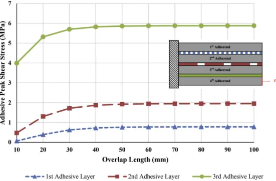
Fig. 15. Adhesive peak shear stress as a function of the overlap length in the case of 1D-bar ME model.
distribution compared to 1D-bar model due to the kinematic hypotheses taken. Fig. 13 reveals that the last adhesive layer has similar mechanical behavior whereas the adhesive shear stress distribution along the overlap of the first and the middle adhesive layer is located in the negative area. In addition, what can be clearly seen in Fig. 14 is the maximum adhesive peak peel stress in the middle adhesive layer.
4.2. Influence of overlap length
As an application of the simplified stress analyzed based on ME models, the influence of the overlap length on the maximal adhesive shear stress of multilayered adhesively bonded joint is studied consid-ering fixed mesh density as 10 MEs per mm. The analyses are conducted
for the overlap lengths from 10 mm to 100 mm by an increase of 10 mm. Within 1D-bar framework, as the overlap lengths of 3 interfaces in-crease, the maximal adhesive shear stresses inin-crease, and then tend to be a finite value as shown in Fig. 15. Therefore, it is not useful to increase the overlap length to decrease maximal shear stress. As Fig. 16 shows, as the overlap length in the presented 1D-beam model increases, the maximal adhesive shear stress of the third adhesive layer increases above x-axis while the maximal adhesive shear stresses of the first and second adhesive layers slightly increase below x-axis. These peak shear stresses remain stable above a certain value of the overlap length. As for the adhesive peak peel stresses for three adhesive layers shown in
Fig. 17, the maximum stresses reach a peak at L ¼ 20 mm. After the peak, what stands out is that the maximum peel stresses decrease and
Fig. 17. Adhesive peak peel stress as a function of the overlap length in the case of 1D-beam ME model.
then tend to be a finite value above 30 mm. It can be concluded that it is not profitable to increase the overlap length to decrease adhesive maximal peel stress. Also, the mechanical behavior along the overlap has the same adhesive stress distributions in both 1D-bar and 1D-beam models in terms of different overlap lengths as presented in Figs. 12–14.
4.3. Influence of adherend thickness
The adhesive peak stresses as a function of the adherend thickness are given in Figs. 18–20. In order to understand the effect of the adherend thickness on the adhesive peak stresses, the mechanical ana-lyses are performed for different adherend thicknesses from 0.2 mm to 2 mm by an increase of 0.2 mm. For 1D-bar model shown in Fig. 18, as the thickness of the adherends increases, the peak shear stresses of all interfaces decrease and then tend to be a finite value. Therefore, it is not useful to use thicker adherends above a certain value to decrease the
maximal shear stress in the case of multilayered bonded joints. Within 1D-beam scheme, the use of thicker adherends leads to a reduction in the maximal adhesive shear stress of the three adhesive layers but then these peak stresses remain stable, as shown in Fig. 19. Fig. 20 shows that there has been a sharp increase up to 0.4 mm of adherend thickness on the maximum adhesive peel stress of second adhesive layer by increasing the adherend thickness. After reaching a peak around 0.4 mm, these maximum peel stress continuously decrease. Compared to the second adhesive layer, there has been a slight decrease in the first and third adhesive layer. After the peak value at 0.4 mm of the adherend thick-ness, maximum adhesive peel stresses fall in the three adhesive layers while the drop in the second adhesive layer is sharper than others. This non-monotonic behavior remains unexplained. It can be deduced that the maximum peel stress can be reduced by increasing the adherend thickness. In addition, for different adherend thicknesses, the stress distributions along the overlap vary as presented in Figs. 12–14.
Fig. 19. Adhesive peak shear stress as a function of the adherend thickness in the case of 1D-beam ME model.
5. Conclusion
This paper set out to perform the stress analysis of the multilayered adhesively bonded joints using a semi-analytical resolution method. The second aim of this study was to investigate the effects of the different parameters in order to understand the mechanical behavior of multi-layered adhesively bonded joints. A comparison between simplified and refined stress analyses of multilayered adhesively bonded structures subjected to pure mechanical tensile in-plane loading is presented. The simplified stress analyses are performed using 1D-bar and 1D-beam ki-nematics in order to predict the mechanical behavior of such joints. The ME technique is a semi-analytical resolution method used for the simplified stress analysis. Firstly, the simplified approach based on simplifying hypotheses is developed to model the joints. The ME tech-nique is the resolution scheme used for the simplified stress analysis. A multilayered bonded-bars and a multilayered bonded-beams MEs are derived in the frame of linear elastic adhesive behavior. The detailed mathematical derivation is presented. For the purpose of validation, the results obtained by the simplified 1D-bar and 1D-beam MEs are compared with the results predicted by 1D-FE models [29]. Mesh in-fluence studies are performed using different mesh densities in order to validate the ME mode. Relative differences between 1D-FE and 1D-ME models for different mesh densities are computed in terms of adhesive stresses. The results of this study show that the method is validated by 1D-FE model by computing small relative differences. These results, therefore, need to be interpreted with the caution that 1D-FE and 1D-ME models assume the same hypotheses and these hypotheses lead to the same results for 1D-bar model and close results for 1D-beam model. For 1D-beam model, it is found that there is a dependency on the number of MEs. Finally, parametric studies of 1D-ME models are presented con-sisting of the analysis of the influence of the overlap length and the adherend thickness. The outputs of these parametric studies are taken as adhesive peak shear and peel stresses in order to evaluate the results. The findings of this research provide insights for the computational time in the use of ME technique. This semi-analytical resolution has the advantage of the computational time for the small mesh sizes and so high number of elements through software code developed for the nu-merical analysis. Furthermore, the number of layers is not a restriction because a different number of layers are able to be simulated depending on the requirements. This presented simplified stress analysis will be of interest to deduce the sizing guidelines in order to perform the pre-liminary design. More broadly, further research in this field would be needed to determine the mechanical analysis of non-linear adhesive behavior.
Acknowledgment
This work has not received any specific grant.
Appendix A. Supplementary data
Supplementary data to this article can be found online at https://doi. org/10.1016/j.ijadhadh.2019.102497.
References
[1] Hart-Smith LJ. Design methodology for bonded-bolted composite joints. Volume I. Analysis derivations and illustrative solutions. California: Long Beach; 1982. [2] Higgins A. Adhesive bonding of aircraft structures. Int J Adhesion Adhes 2000;20:
367–76. https://doi.org/10.1016/S0143-7496(00)00006-3.
[3] Kelly G. Quasi-static strength and fatigue life of hybrid (bonded/bolted) composite single-lap joints. Compos Struct 2006;72:119–29. https://doi.org/10.1016/j. compstruct.2004.11.002.
[4] da Silva LFM, €Ochsner A, Adams RD. Handbook of adhesion technology. second ed., vols. 1–2. Heidelberg: Springer; 2018. https://doi.org/10.1007/978-3-319- 55411-2.
[5] van Ingen JW, Vlot A. Stress analysis of adhesively bonded single lap joints. (Report LR-740). Delft Univ Technol; 1993.
[6] Tsai MY, Morton J. An evaluation of analytical and numerical solutions to the single-lap joint. Int J Solids Struct 1994;31:2537–63. https://doi.org/10.1016/ 0020-7683(94)90036-1.
[7] da Silva LFM, das Neves PJC, Adams RD, Spelt JK. Analytical models of adhesively bonded joints - Part I: literature survey. Int J Adhesion Adhes 2009;29:319–30. https://doi.org/10.1016/j.ijadhadh.2008.06.005.
[8] Volkersen O. Die Nietkraftverteilung in zugbeanspruchten Nietverbindungen mit konstanten Laschenquerschnitten. Luftfahrtfor Schung 1938;15:41–7. [9] Goland M. The stresses in cemented joints. J Appl Mech 1944;17.
[10] Hart-Smith LJ. Adhesive-bonded scarf and stepped-lap joints. California: Long Beach; 1973.
[11] Hart-Smith LJ. Adhesive-bonded single-lap joints. California: Long Beach; 1973. [12] Hart-Smith LJ. Adhesive-bonded double-lap joints. California: Long Beach; 1973. [13] Bigwood DA, Crocombe AD. Elastic analysis and engineering design formulae for bonded joints. Int J Adhesion Adhes 1989;9:229–42. https://doi.org/10.1016/ 0143-7496(89)90066-3.
[14] Oplinger DW. A layered beam theory for single lap joints. 1991.
[15] Tsai MY, Oplinger DW, Morton J. Improved theoretical solutions for adhesive lap joints. Int J Solids Struct 1998;35:1163–85. https://doi.org/10.1016/S0020-7683 (97)00097-8.
[16] Alfredsson KS, H€ogberg JL. A closed-form solution to statically indeterminate adhesive joint problems-exemplified on ELS-specimens. Int J Adhesion Adhes 2008;28:350–61. https://doi.org/10.1016/j.ijadhadh.2007.10.002.
[17] Luo Q, Tong L. Fully-coupled nonlinear analysis of single lap adhesive joints. Int J Solids Struct 2007;44:2349–70. https://doi.org/10.1016/j.ijsolstr.2006.07.009. [18] Weißgraeber P, Stein N, Becker W. A general sandwich-type model for adhesive
joints with composite adherends. Int J Adhesion Adhes 2014;55:56–63. https:// doi.org/10.1016/j.ijadhadh.2014.06.009.
[19] Paroissien E. Contribution aux assemblages hybrides (Boulonn�es/Coll�es) – application aux jonctions a�eronautiquesvol. III. Universit�e de Toulouse; 2006. [20] Paroissien E, Sartor M, Huet J. Hybrid (bolted/bonded) joints applied to aeronautic
parts: analytical one-dimensional models of a single-lap joint. In: Tichkiewitch S, Tollenaere M, Ray P, editors. Adv. Integr. Des. Manuf. Mech. Eng. II. Dordrecht: Springer; 2007. p. 95–110.
[21] Paroissien E, Sartor M, Huet J, Lachaud F. Analytical two-dimensional model of a hybrid (Bolted/Bonded) single-lap joint. J Aircr 2007;44:573–82. https://doi.org/ 10.2514/1.24452.
[22] Paroissien E, Lachaud F, Jacobs T. A simplified stress analysis of bonded joints using macro-elements. In: Kumar S, Mittal KL, editors. Advances in modeling and design of adhesively bonded bonded systems. Adv. Model. Des. Adhes. Bond. Syst., Beverly: Wiley-Scrivener; 2013. p. 93–146. https://doi.org/10.1002/
9781118753682.
[23] Paroissien E, Gaubert F, Da Veiga A, Lachaud F. Elasto-plastic analysis of bonded joints with macro-elements. J Adhes Sci Technol 2013;27:1464–98. https://doi. org/10.1080/01694243.2012.745053.
[24] Lelias G, Paroissien E, Lachaud F, Morlier J, Schwartz S, Gavoille C. An extended semi-analytical formulation for fast and reliable mode I/II stress analysis of adhesively bonded joints. Int J Solids Struct 2015;62:18–38. https://doi.org/ 10.1016/j.ijsolstr.2014.12.027.
[25] Paroissien E, Lachaud F, Schwartz S, Da Veiga A, Barri�ere P. Simplified stress analysis of hybrid (bolted/bonded) joints. Int J Adhesion Adhes 2017;77:183–97. https://doi.org/10.1016/j.ijadhadh.2017.05.003.
[26] Paroissien E, Lachaud F, Morlier J, Schwartz S. A direct method for the assessment of cohesive zone models for thin adhesive layers loaded in mode I, mode II, and mixed-mode I/II. Rev Adhes Adhes 2018. https://doi.org/10.7569/
raa.2018.097301.
[27] Paroissien E, da Silva LFM, Lachaud F. Simplified stress analysis of functionally graded single-lap joints subjected to combined thermal and mechanical loads. Compos Struct 2018;203:85–100. https://doi.org/10.1016/j.
compstruct.2018.07.015.
[28] L�elias G, Paroissien E, Lachaud F, Morlier J. Experimental characterization of cohesive zone models for thin adhesive layers loaded in mode I, mode II, and mixed-mode I/II by the use of a direct method. Int J Solids Struct 2019;158: 90–115. https://doi.org/10.1016/j.ijsolstr.2018.09.005.
[29] Paroissien E, Lachaud F, da Silva LFM, Seddiki S. A comparison between macro- element and finite element solutions for the stress analysis of functionally graded single-lap joints. Compos Struct 2019;215:331–50. https://doi.org/10.1016/j. compstruct.2019.02.070.
[30] Nairn JA, Mendels DA. On the use of planar shear-lag methods for stress-transfer analysis of multilayered composites. Mech Mater 2001;33:335–62. https://doi. org/10.1016/S0167-6636(01)00056-4.
[31] Jiang G, Peters K. A shear-lag model for three-dimensional, unidirectional multilayered structures. Int J Solids Struct 2008;45:4049–67. https://doi.org/ 10.1016/j.ijsolstr.2008.02.018.
[32] Viet NV, Zaki W, Umer R. Interlaminar shear stress function for adhesively bonded multi-layer metal laminates. Int J Adhesion Adhes 2018;82:14–20. https://doi.org/ 10.1016/j.ijadhadh.2017.12.011.
[33] Pham P Van, Mohareb M, Fam A. Finite element formulation for the analysis of multilayered beams based on the principle of stationary complementary strain energy. Eng Struct 2018;167:287–307. https://doi.org/10.1016/j.
engstruct.2018.04.014.
[34] Simo JC, Laursen TA. An augmented Lagrangian treatment of contact problems involving friction. Comput Struct 1992;42:97–116. https://doi.org/10.1016/0045- 7949(92)90540-G.
[35] Dechwayukul C, Rubin CA, Hahn GT. Analysis of the effects of thin sealant layers in aircraft structural joints. AIAA J 2003;41:2216–28.