HAL Id: hal-01377478
https://hal.inria.fr/hal-01377478
Submitted on 7 Oct 2016
HAL is a multi-disciplinary open access
archive for the deposit and dissemination of
sci-entific research documents, whether they are
pub-lished or not. The documents may come from
teaching and research institutions in France or
abroad, or from public or private research centers.
L’archive ouverte pluridisciplinaire HAL, est
destinée au dépôt et à la diffusion de documents
scientifiques de niveau recherche, publiés ou non,
émanant des établissements d’enseignement et de
recherche français ou étrangers, des laboratoires
publics ou privés.
Distributed under a Creative Commons Attribution| 4.0 International License
Augmented Reality Simulation of CAM Spatial Tool
Paths in Prismatic Milling Sequences
Saša Ćuković, Goran Devedžić, Frieder Pankratz, Khalifa Baizid, Ionut
Ghionea, Andreja Kostić
To cite this version:
Saša Ćuković, Goran Devedžić, Frieder Pankratz, Khalifa Baizid, Ionut Ghionea, et al.. Augmented
Reality Simulation of CAM Spatial Tool Paths in Prismatic Milling Sequences. 12th IFIP
Interna-tional Conference on Product Lifecycle Management (PLM), Oct 2015, Doha, Qatar. pp.516-525,
�10.1007/978-3-319-33111-9_47�. �hal-01377478�
Augmented Reality Simulation of CAM Spatial Tool
Paths in Prismatic Milling Sequences
Saša Ćuković1, Goran Devedžić1, Frieder Pankratz2, Khalifa Baizid3, Ionut Ghionea4, Andreja Kostić1
1University of Kragujevac, Faculty of Engineering, Kragujevac, Serbia.
[email protected], [email protected], [email protected]
2Technical University of Munich, CAMPAR, Germany.
3Ecole des Mines de Douai, Douai, France
4University Politehnica of Bucharest, Bucharest, Romania.
Abstract. Augmented Reality (AR) technology to support learning activities
becomes a trend in education and effective teaching aids for engineering courses. This paper presents initial results of a project aimed to transform the current learning process of Computer Aided Manufacturing (CAM) by designing and implementing an interactive AR learning and simulation tool to help students to develop a comprehensive understanding of technological models and features in milling processes. We present a marker-based platform that uses AR as a medium for representation of prismatic milling processes to facilitate CAM education and it should enable a faster comprehension of complex spatial paths and overall machining system.
Keywords: Augmented Reality Aided Manufacturing, Prismatic Machining,
CAD/CAM, Simulation, NC, Milling.
1 Introduction
Augmented reality (AR) is a technology which renders CAD objects into the real scene by registering virtual CAD model over a user’s view in real world at real-time (in situ) [1], [2]. With additional information embedded in CAD models physical world can be enhanced/augmented beyond user’s normal experiences and perceptions. The user can interact with digital information projected onto the real surfaces within a workspace in natural manner. On the other hands, modern CAD/CAM software offer an overwhelming variety of complex features, models and processes in multimodular product development and production. With augmented reality, CAD models and CAM simulations can be extended for better perceptions of digital 3D design and manufacturing process. This article introduces the applications of AR technology in
practical CAD/CAM education and simulation of milling process, and will discuss the significance of AR based learning in machining process planning. The core of this interactive system consists of video image processing techniques and interactive 3D simulation of tool movements in a specific milling sequence.
2 Augmented Reality
The concept of an Augmented Reality based Magic Book was firstly introduced in 1997 [4]. The basic principle is that a real book is enhanced using Augmented Reality (Fig.1). Virtual objects are superimposed on the different pages of the book in the Augmented Reality mode. If the user is interested in a specific scene, he can fly into the scene by switching to the Virtual Reality mode and inspect it from the inside.
In recent years Android smart phones and tablets became an increasingly popular devices for AR, combining all needed components (camera, display and processing power) for video based Augmented Reality in a compact form [5].
Fig. 1. Concept of Augmented Reality in the Reality-Virtuality Continuum [3] For this reason and the fact that smart phones and tablets became widespread devices we choose to build our system as a video based Augmented Reality system for Android devices. Also, it is important to emphasize that there are marker-based and markerless-based principles of AR algorithms [3], [4].
2.1 Augmented Reality Aided Manufacturing
Generally, AR is a concept of enhancing the real world with additional virtual information and it can be used to create an integration of process data with workspace of an industrial CNC machine (Fig.2). Independent of specific technologies, an AR system has to meet the following requirements: Combine real and virtual worlds, Augmentations are interactive in real time, Augmentations are registered in 3D to the real world.
Fig. 2. Representation of ARAM – Augmented Reality Aided Manufacturing This concept also included multi-scale collaboration, which enables multiple users to experience the same virtual environment. For our system we omitted the Virtual Reality mode as it is impractical for our application. We still have support for collaboration, as several users can see the same virtual model on the book page.
3 Computer Aided Manufacturing – CAM
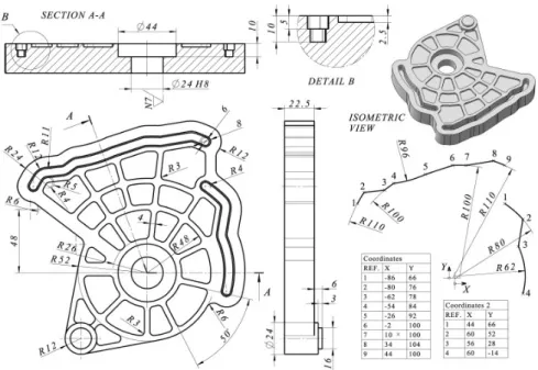
Based on CAD models and specific drawings (Fig.3), operators are able to generate technological features and NC code for physical material removing. In that course we used standard procedures to prepare technological model of milling in the CAM (Computer Aided Manufacturing) module.
3.1 Creating 2.5D milling sequences
In the case of production computer-aided process planning (CAPP) in milling sequences, stock part is fixed, by the fixtures on the machine table in the XY plane, while the tool axis is directed in Z axis of the machine. Based on the shape of pockets, tool path styles may be different and may combine linear and/or circular segments (linear, counterclockwise and clockwise interpolations). In the 2.5D milling operation, we defined the following technological features:
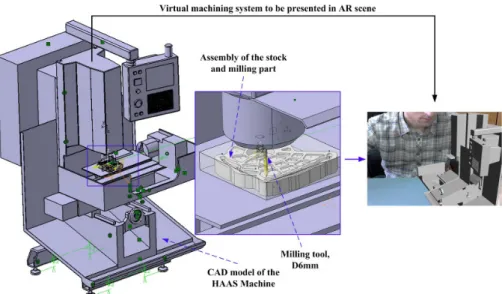
1. Machine system (HAAS 3-axis Machine.1), stock part (164x164x30mm) and machining part;
2. Default reference machining axis located on the stock corner;
3. Models of fixture devices, safety planes and default tool change point;
4. Parameters of the machining process (feed rates, spindle speeds, feeds and speeds, approach/retract, etc.) and machine tools;
5. Geometry of the machining part and stock (volumes, planes, islands, contours, curves, etc.);
6. Milling strategies (axial, radial, profile), and styles (spiral, back and forth, one way, inward helical, etc.).
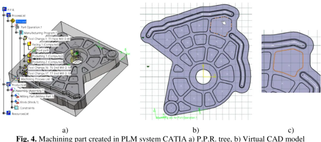
By defining and simulating all milling sequences in CAM modules like Prismatic Machining in PLM system CATIA [6], user generate P.P.R. structure of the process and manufacturing program, easy to edit in the future if needed (Fig.4).
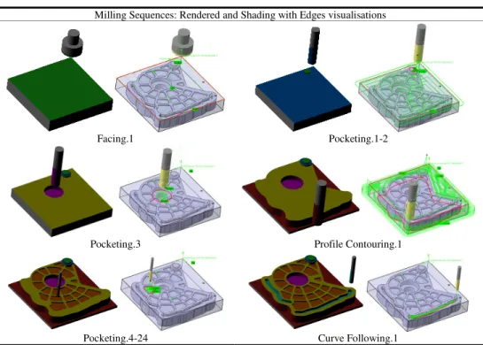
Table 1. Table of milling sequences in prismatic machining of machining part.
Milling Sequences: Rendered and Shading with Edges visualisations
Facing.1 Pocketing.1-2
Pocketing.3 Profile Contouring.1
In order to obtain the final shape of the part, we combined facing, pocketing, profile contouring and curve following operations in just one program. Some of the milling sequences are given in Table 1.
a) b) c)
Fig. 4. Machining part created in PLM system CATIA a) P.P.R. tree, b) Virtual CAD model
and c) selected milling pocket
3.2 Manufacturing Program Code - CATNCode
After post processing the APT code using postprocessor Sinumerik_840D_3X.pp, CATNCcode is generated, and for specific level of selected pocketing milling it has the following commands, presented in Table 2.
Table 2. NC code for specific tool paths.
NC code Tool paths
N11460 ;========= TOOL CHANGE ============= N11470 ; DESC : N11480 ;=================================== N11490 T8 M06 N11500 D0 N11510 G0 G90 G40 G17 N11520 G94 F2000 S1200 M3 N11530 G64 SOFT N11540 G1 X122.196 Y127.852 Z19 F400 N11550 Z-4.759 N11560 X127.699 Y124.839 Z-5.088 N11570 X129.305 Y126 Z-5.192 N11580 X131.019 Y126.992 Z-5.296 N11590 X131.436 Y129.227 Z-5.415 N11600 X131.072 Y129.233 Z-5.434 N11610 X122.666 Y129.393 Z-5.875 N11620 X122.196 Y127.852 Z-5.959 N11780 G2 X131.019 Y126.992 I12.277 J-15.293 N11790 G1 X131.436 Y129.227 N11800 X131.072 Y129.233 N11810 X131.101 Y130.733 N11820 X131.129 Y132.233 N11830 X120.458 Y132.436 … N12950 G2 X129.81 Y112.587 I-26.62 J-70.117 N12960 G2 X138.891 Y120.102 I10.166 J-3.041 N12970 G1 X141.364 Y133.383 N12980 X134.138 Y138.177 N12990 X131.243 Y138.232 N13000 Z19 F2000
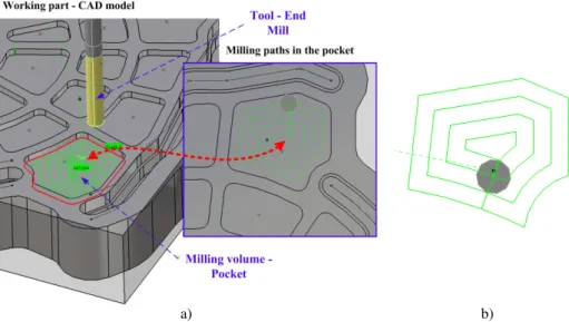
From those NC commands, we extracted segments of paths and movements in xyz coordinates and transfer them to AR platform in order to simulate the tool’s movement over the 3D model, on the screen (Fig.5).
a) b)
Fig. 5. Prismatic milling of the pocket: a) tool approaching pocket along Z axis, b) tool path in
the XY plane after simulation
To demonstrate the AR possibilities on a specific milling sequence we selected Pocketing.7 from Part Operation/Manufacturing program (Fig.5) to check process virtually before physical machining (Fig.6).
Fig. 6. Real machining part and pocket after milling
All CAD models from PLM system CATIA are exported in appropriate format *.wrl, and then in *.obj. We involved CAD model of the machine HAAS in order to represent overall system (Fig.7).
Fig. 7. Machine tool - CAD model of the HAAS CNC machine, simplified representation
4 Proposed AR system
Our AR system is composed of a tracking framework to provide the necessary tracking data and an advanced software engine for rendering the virtual models and interaction with the augmentations.
4.1 System description
As the tracking framework we are using UbiTrack [7]. UbiTrack is an open source, general purpose tracking framework for Augmented Reality developed by CAMPAR group (TUM Munich, Germany). UbiTrack has been successfully adopted to Microsoft Windows, Linux, Mac OS and Android [9]. For the software engine we are using Unity3D [8] for the ease of use and its platform independency. This allows us to deploy our application to all desktop systems and Android devices without any need to change the source code of the application.
To fulfill all requirements for an AR system, the key step is to estimate the position and orientation of the camera in respect to the axis of the scene. To do this we employ a technique called “marker tracking”, in the case of QR marker based augmented reality system [10], [11].
4.2 Marker tracker
Marker tracking means finding an optical square marker in the scene and estimating its relative position to the camera. A squared QR marker has an encoded ID and consists of a black square with a white border and a predefined size and shape of pattern. Different techniques can be used to encode the ID like template matching or
the encoding as a binary number. Key steps of the marker tracking pipeline is illustrated in Figure 8.
Fig. 8. Marker tracker pipeline – 2D image processing and recognitions
In the first step the image from the camera is converted to a gray scale image to speed up the image processing in all further steps. Since the square markers are only black and white we can threshold the gray image in the second step to generate a binary image. This will remove noise and most of the environment from the image, which again allows a much faster processing for the next step.
The third step consists of finding all of the contours that are left in the binary image. Of these contours only contours with exactly four corners are selected as potential square markers for the following steps. In step five, the algorithm tries to determine whether a specific rectangle is a part of an optical square marker or a part of the environment by extracting the ID of the marker from the gray image.
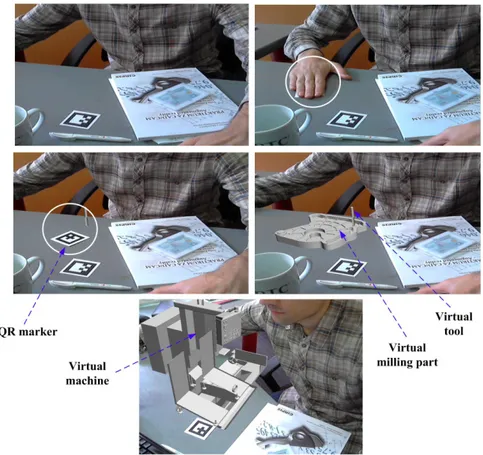
By using the camera image as the background (real world) in our display and using the pose of the marker we now can superimpose the camera image with the virtual object (virtual world) [12]. When the marker or camera is moved the augmentation stays on the marker (registered in 3D). The marker tracking pipeline is computationally inexpensive, so we can keep all interactions with the virtual objects in real time (Fig.9). This paper discusses how spatial augmented reality may be used to support understanding of milling operations in the machining processes, by projecting augmentations (machines, machining parts, tools, NC paths) on objects in real machining system [13].
By recognizing the ID of the square-sized marker, the application determines which CAD model to display in the scene. The 3D model database is created using educational PLM system CATIA. Employing desktop version of developed AR platform and a camera, operators are able to go through the entire process. Focusing the camera on the markers retrieve the virtual 3D objects from database and the information and graphics are then overlaid onto the screen (Fig.9) [14]. The database may be updated with new models even by operators that have a little knowledge about programming.
5 Conclusions
In this paper, we are focused on moveable interactive augmentations of 3D model of milling tool and its displaying in the correct position in the specific milling pocket. The proposed system makes possibility to enhance visibility of occluded tools as well as to visualize real-time data from the machining process by adding visual feedback to augment and amplify operator’s sense and understanding and simplifying operation. In the near future, our aim is to highlight current NC (Numerical Control) code in current operation and overlay textual G-code and M-code instructions on the screen. The proposed system can be used as a simulator which allows virtual experiments with combinations of virtual tools without the need for destructive and costly physical testing. The operation information and other media (e.g. pictures, animations, videos, etc.) can be also projected onto the screen or physical surface of the machining part in the scene.
Acknowledgments. This work is supported by project “Application of Biomedical
Engineering in Preclinical and Clinical Practice”, supported by the Serbian Ministry of Education, Science and Technological Development (III-41007). The work of Ionut Ghionea was supported by the Sectorial Operational Programme Human Resources Development 2007-2013 of the Ministry of EU Funds through the Financial Agreement POSDRU/159/1.5/S/138963.
References
1. Zhou, J., Lee, I., Thomas, B., Menassa, R., Farrant, A., Sansome, A.: In-Sity Support Automotive Manufacturng Using Spatial Augmented Reality, Int. J. Virt. Real. Vol. 11, pp. 33--41, (2012)
2. Azuma, Ronald T.: A Survey of Augmented Reality, In: Teleoperators and Virtual Environments, vol.6, pp.355--385, (1997)
3. Ćuković, S., Pankratz, F., Devedžić, G., Klinker, G., Luković, V., Ivanović, L.: An Interactive Augmented Reality Platform for CAD Education, In: 35th Conference on Production Engineering, pp.353--356, Kopaonik, ISBN 978-86-82631-69-9 (2013) 4. Cukovic, S., Gattullo, M., Pankratz, F., Devedzic, G., Carrabba, E., Baizid, K.: Marker
Based Vs. Natural Feature Tracking Augmented Reality Visualization of the 3d Foot Phantom, In: International Conference on Electrical and Bio-medical Engineering, Clean Energy and Green Computing (EBECEGC2015), Dubai, United Arab Emirates, pp. 24--31, ISBN 978-1-941968-06-2, (2015)
5. Wagner, D., Reitmayr, G., Mulloni, A., Drummond, T., Schmalstieg, D.: Pose Tracking from Natural Features on Mobile Phones, In: 7th IEEE/ACM International Symposium on Mixed and Augmented Reality, pp. 125--134, (2008)
6. Software Dassault System CATIA - Student version V5R20:
http://www.3ds.com/products-services/catia/welcome (visited on 07/05/2015)
7. UbiTrack, http://campar.in.tum.de/UbiTrack/WebHome (visited on 07/05/2015) 8. Unity3D, http://www.unity3d.com (visited on 07/05/2015)
9. Wagner, D., Reitmayr, G., Mulloni, A., Drummond, T., Schmalstieg, D.: Real-time Detection and Tracking for Augmented Reality on Mobile Phones, IEEE Trans. Vis. Comp. Graph., vol.16, pp. 355--368, (2010)
10. Pengcheng, F., Mingquan, Z., Xuesong, W.: The Significance and Effectiveness of Augmented Reality in Experimental Education, In: International Conference on E-Business and E-Government (ICEE), pp.1--4, (2011)
11. Pustka, D., Huber, M., Bauer, M., Klinker, G.: Spatial Relationship Patterns: Elements of Reusable Tracking and Calibration Systems, In: 5th IEEE and ACM International
Symposium on Mixed and Augm. Reality, pp.88--97, (2006)
12. Heen C., Kaiping F., Chunliu M., Siyuan C., Zhongning G., Yizhu H.: Application of Augmented Reality in Engineering Graphics Education, In: International Symposium on IT in Medicine and Education (ITME), pp. 362--365, (2011)
13. Novak-Marcincin, J., Barna, J., Janak, M., Novakova-Marcincinova, L.: Augmented Reality Aided Manufacturing, In: 2013 International Conference on Virtual and Augmented Reality in Education, pp. 01--09, (2013)
14. Ćuković, S., Devedžić, G., Pankratz, F., Ghionea, I., Subburaj, K.: Praktikum za CAD/CAM - Augmented Reality -, University of Kragujevac, Faculty of Engineering, CIRPIS, Kragujevac, Serbia, ISBN 978-86-6335-020-5, (2015)
![Fig. 1. Concept of Augmented Reality in the Reality-Virtuality Continuum [3]](https://thumb-eu.123doks.com/thumbv2/123doknet/12572670.346012/3.892.316.580.522.750/fig-concept-augmented-reality-reality-virtuality-continuum.webp)