HAL Id: hal-00760772
https://hal.archives-ouvertes.fr/hal-00760772
Submitted on 4 Dec 2012HAL is a multi-disciplinary open access
archive for the deposit and dissemination of sci-entific research documents, whether they are pub-lished or not. The documents may come from teaching and research institutions in France or
L’archive ouverte pluridisciplinaire HAL, est destinée au dépôt et à la diffusion de documents scientifiques de niveau recherche, publiés ou non, émanant des établissements d’enseignement et de recherche français ou étrangers, des laboratoires
Proposition of Dynamic Virtual Link for IPv6
GeoNetworking (GN6) in ETSI
Manabu Tsukada, Masatoshi Kakiuchi, Thierry Ernst
To cite this version:
Manabu Tsukada, Masatoshi Kakiuchi, Thierry Ernst. Proposition of Dynamic Virtual Link for IPv6 GeoNetworking (GN6) in ETSI. 2012. �hal-00760772�
Proposition of Dynamic Virtual Link
for IPv6 GeoNetworking (GN6) in ETSI
29th November 2012
Manabu Tsukada, INRIA, France Masatoshi Kakiuchi, NAIST, Japan Thierry Ernst, Mines ParisTech, France
Contents
1 Background 2
2 Geographic Virtual Link 2
3 Topological Virtual Link 3
4 Limitation of Draft EN 302 636-6-1 V0.1.2 (2012-11) 3
4.1 V2V scenario . . . 3
4.2 Router solicitation with GVL . . . 3
4.3 Geographical scoped communication . . . 3
4.4 Dropped Packet before checking IPv6 routing table . . . 4
5 Proposition of Dynamic Virtual Link (DVL) 4 5.1 Definition . . . 5
5.2 Property . . . 5
6 Modified Operations 6 6.1 IPv6 Link-local Unicast . . . 6
6.2 IPv6 Link-local Multicast . . . 8
6.3 IPv6 Global Unicast . . . 8
6.4 IPv6 Global Multicast . . . 8
7 Consideration 9 7.1 About TVL . . . 9
7.2 Router Advertisement with Unicast . . . 9
1. BACKGROUND
8 Conclusion 10
1
Background
Intelligent Transportation Systems (ITS) are systems deployed to optimize the road traffic and realize safe, efficient and comfortable human mobility. Cooperative ITS is a new vision of ITS where vehicles, the roadside infrastructure, traffic control centers, road users, road authorities, road operators, etc. exchange and share information based on a common communication architecture — known as the ITS station reference architecture [ISO-21217-CALM-Arch,ETSI-EN-302-665-Arch] — supporting all types of ITS use cases over a diversity of access technologies (11p, 11n, 3G/4G, infra-red, ...). The building blocks of the ITS station are specified within ISO, ETSI, IETF and IEEE.
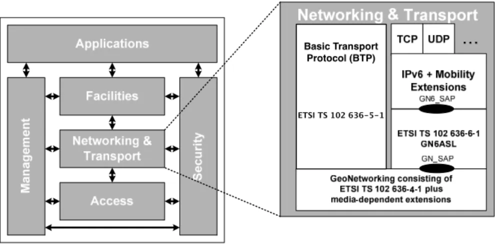
[ETSI-TS-102-636-6-1-GN6] specifies the transmission of IPv6 packets over ETSI GeoN-etworking protocol [ETSI-TS-102-636-4-1-GN] via a protocol adaptation sub-layer referred as the GN6ASL (GeoNetworking to IPv6 Adaptation Sub-layer) (See Figure1).
Figure 1: GN6ASL in the ITS station architecture
ETSI TS 102 636-5-1 Basic Transport
Protocol (BTP)
Figure 1: GN6ASL in the ITS station architecture
2
Geographic Virtual Link
The definition of Geographical Virtual Link (GVL) in [ETSI-TS-102-636-6-1-GN6] is de-scribed as bellow:
A Geographical Virtual Link (GVL) is a link-local multicast-capable virtual link spanning multiple physical links with geographically scoped boundaries.
Each GVL shall be associated with one single GeoNetworking GEOBROAD-CAST/GEOANYCAST area stored in the per-GVL MIB attributes (itsGn6aslGvlAreaCenterLatitude, itsGn6aslGvlAreaCenterLongitude, itsGn6aslGvlAreaDistA itsGn6aslGvlAreaDistB and itsGn6aslAreaAngle). These attributes are referred to as the GVL Area and shall be:
3. TOPOLOGICAL VIRTUAL LINK
• derived from a received GeoNetworking header encapsulating a Router Advertisements (RA) message [11] as described in clause 10.2.1; or
• assigned by the ITS station management entity only in roadside ITS stations.
3
Topological Virtual Link
The definition of Topological Virtual Link (TVL) in [ETSI-TS-102-636-6-1-GN6] is de-scribed as bellow:
A Topological Virtual Link (TVL) is a non-broadcast multi-access (NBMA) virtual link spanning multiple physical links with topologically scoped bound-aries. IPv6 multicast traffic may not be exchanged through a TVL.
4
Limitation of Draft EN 302 636-6-1 V0.1.2 (2012-11)
We describe the limitation of Draft EN 302 636-6-1 V0.1.2 (2012-11) in the Section. Note that this study is based on year November 2012 versions of the ETSI Standards and that the standards constantly evolve. As a result, parameters, primitives and virtual links on GN6ASL may have changed at the time of reading.
4.1 V2V scenario
As GVL is created upon the reception of Router Advertisements from Access Routers spe-cified in [rfc4862], the communication using GVL cannot be enabled before the reception of RA. TVL is not used for multicast nor geographical scoped communication (i.e. Geo-Broadcast). Thus current specification will not work in the V2V scenarios where there are no infrastructure around the vehicles.
4.2 Router solicitation with GVL
As GVL is created upon the reception of Router Advertisements from Access Routers, the communication using GVL cannot be enabled before the reception of RA. Thus the mobile router cannot send the router solicitation before receiving the RA. Usually, the router solicitation should be sent in order to solicit the router advertisement from access router.
4.3 Geographical scoped communication
The GeoArea of GVL is configured in access router and shared among all the GeoAdhoc router. Thus no GeoAdhoc router can configure the GeoArea of Geographic scoped com-munication in GN6ASL, except for access router. In other words, the application in the vehicle ITS Station cannot configure the destination GeoArea of GeoBroadcast, but only select the existent GVLs created by RA at the moment.
5. PROPOSITION OF DYNAMIC VIRTUAL LINK (DVL)
4.4 Dropped Packet before checking IPv6 routing table
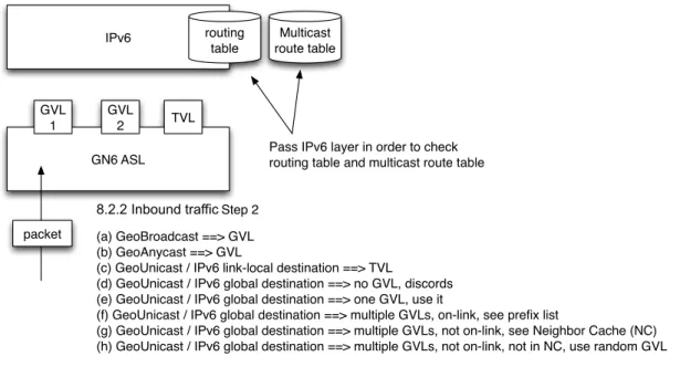
Upon the reception of IPv6 GeoNetworking packet on GN6ASL, GN6ASL must select the virtual link to pass the IPv6 packet to IPv6 layer. However, in the current specification, the some IPv6 packets are dropped in GN6ASL without checking the routing table nor the multicast route table, even when the received node is the GN destination or received node is inside the destination GeoArea. This is because current rule of virtual interface selection has the case where the received IPv6 packets does not matched with any of the virtual interface selection rules in GN6ASL (See figure2 for simplified selection rule, and see Section 8.2.2 in [ETSI-TS-102-636-6-1-GN6] for detail).
!"#$ %&'()*+, (-./0 12$,345 165 7 165 8 965 :-;<0( "-==,!"#$,/->0%,)*,&%?0%,(&,;@0;<, %&'()*+,(-./0,-*?,A'/();-=(,%&'(0,(-./0 !"#"#$%&'()&*$+,-../0!4(0:,8 B-C,10&D%&-?;-=(,EEF,165 B.C,10&3*>;-=(,EEF,165 B;C,10&G*);-=(,H,!"#$,/)*<I/&;-/,?0=()*-()&*,EEF,965 B?C,10&G*);-=(,H,!"#$,+/&.-/,?0=()*-()&*,EEF,*&,165J,?)=;&%?=, B0C,10&G*);-=(,H,!"#$,+/&.-/,?0=()*-()&*,EEF,&*0,165J,'=0,)( BKC,10&G*);-=(,H,!"#$,+/&.-/,?0=()*-()&*,EEF,A'/():/0,165=J,&*I/)*<J,=00,:%0LM,/)=( B+C,10&G*);-=(,H,!"#$,+/&.-/,?0=()*-()&*,EEF,A'/():/0,165=J,*&(,&*I/)*<J,=00,20)+@.&%,N-;@0,B2NC B@C,10&G*);-=(,H,!"#$,+/&.-/,?0=()*-()&*,EEF,A'/():/0,165=J,*&(,&*I/)*<J,*&(,)*,2NJ,'=0,%-*?&A,165 O'/();-=(, %&'(0,(-./0
Figure 2: Dropped packet before checking IPv6 routing table
Packets are dropped in GN6ASL in following cases (even the receiver is inside of the destination GeoArea, or the receiver is the GN destination of the packet):
• GeoArea of the GeoBroadcast destination does not matched with any of GVL in the receiver, and it does not bring Router advertisement.
• GeoArea of the GeoAnycast destination does not matched with any of GVL in the receiver.
• GeoUnicast brings IPv6 packet to the destination of global address and no GVL exists in the receiver.
5
Proposition of Dynamic Virtual Link (DVL)
To overcome the limitation arisen in Section 4, we propose Dynamic Virtual Link (DVL) in this section. Section 5.1 provides the definition of DVL and Section 5.2 presents the comparison of properties of TVL, DVL and GVL.
5. PROPOSITION OF DYNAMIC VIRTUAL LINK (DVL)
5.1 Definition
A Dynamic Virtual Link (DVL) is multicast-capable virtual link spanning multiple physical links with geographically scoped boundaries.
A DVL is created when the physical interface is up, and exactly one DVL exists per a single physical interface. DVL shall be associated with one single GeoNetworking Geo-Broadcast /GeoAnycast area (also called GeoArea in [ETSI-EN-302-931-GeoArea] and specified in [ETSI-TS-102-636-4-1-GN]) stored in the following DVL MIB attributes:
• itsGn6aslDvlAreaCenterLatitude • itsGn6aslDvlAreaCenterLongitude • itsGn6aslDvlAreaDistA
• itsGn6aslDvlAreaDistB • itsGn6aslDvlAreaAngle
These attributes are referred as the DVL Area and shall be assigned by the ITS station management entity. And if the attributes are not specified, the DVL shall not used to send link-local and global multicast. In the case, DVL is only used for the reception of the packet and sending link-local and global unicast.
Symmetric access is not guaranteed in the communication via DVL, therefore IPv6 ND shall be disabled.
In sender side GN6ASL in a GeoAdhoc Router, DVL is used in V2V scenario where no infrastructure is around the vehicle nor no RA is received as described in Section4.1. Also Router solicitation can be sent via DVL before receiving the Router advertisement in the situation where we described in Section4.2. In addition, destination GeoArea can be specified as the sender needs by configuring DVL Area (i.e. DVL MIB attributes) stored in the management entity.
In the receiver side GN6ASL in a GeoAdhoc router, DVL act as a default interface in the virtual interface selection. Therefore, no packet is dropped in GN6ASL during the virtual selection procedure (See this problem in Section4.4).
5.2 Property
Table1 shows the properties of TVL, DVL and GVL.
TVL is a virtual link spanning multiple physical links with topologically scoped bound-aries (but the boundary is never applied because TVL employes always GeoUnicast as an underlying GN routing mode). On the other hand, DVL and GVL are spanning mul-tiple physical links with geographically scoped boundaries. The scope of DVL (destination GeoArea) is dynamically configured as geographically scoped boundaries in the manage-ment entity in each node and thus it is variable in each nodes connected to the link. The scope of GVL (destination GeoArea) is statically set by the scope of the received router advertisement and is invariable among the nodes connected to the link. As a result, only GVL guarantees symmetric access among the nodes on the link.
Non-broadcast multi-access (NBMA) is adapted in TVL as a virtual interface whereas Ethernet V2.0/IEEE 802.3 LAN virtual interfaces is used in DVL and GVL.
6. MODIFIED OPERATIONS
TVL DVL GVL
Scope Topological scope Geographical scope
Variation of the scope
(Used only for
GeoUnicast. Therefore topological boundary is not applied.)
The scope of the link is dynamically configured and is variable to the nodes in the link.
The scope of the link is static and is
invariable to the nodes in the link Access non-broadcast multi-access (NBMA) multicast-capable Symmetric access
Not guaranteed Guaranteed
Creation When the communication interface is up Each time when the node receives RA over GN
Number of link per single communication
interface
Single link for each communication interface The number of GVL depends on the number of different RAs
IPv6 Address Assignment
Only link local address is assigned Both link-local and global address are assigned
Table 1: Properties of TVL, GVL and DVL
In an access GeoAdhoc router, all of TVL, DVL and GVL are created when the physical communication interface is up. On the other hand, the other GeoAdhoc routers create only only TVL and DVL, but creates no GVL. GVL is setup only by the reception of router advertisement. TVL and DVL exists exactly one per the physical communication interfaces, and GVL is created upon the reception of Router advertisement (thus number of GVL depends on the number of different router advertisement received on the node).
As IPv6 address assignment, only link-local address shall be assigned to TVL and DVL whereas both Global and link-local address is assigned to GVL interfaces. The way of the allocation of the link-local address on TVL, DVL and GVL is proposed in [INRIA-report-extended-IID].
6
Modified Operations
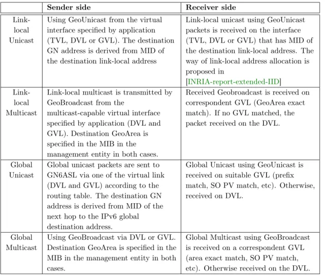
The section describes the modified operation by introducing DVL. The modified operation on both sender and receiver side GeoAdhoc router is summarized in Table2.
6.1 IPv6 Link-local Unicast
IPv6 local unicast shall not be forwarded beyond IPv6 routers. The packet has link-local unicast address in both IPv6 source and destination address, and the communication
6. MODIFIED OPERATIONS
Sender side Receiver side
Link-local Unicast
Using GeoUnicast from the virtual interface specified by application (TVL, DVL or GVL). The destination GN address is derived from MID of the destination link-local address
Link-local unicast using GeoUnicast packets is received on the interface (TVL, DVL or GVL) that has MID of the destination link-local address. The way of link-local address allocation is proposed in
[INRIA-report-extended-IID]
Link-local Multicast
Link-local multicast is transmitted by GeoBroadcast from the
multicast-capable virtual interface specified by application (DVL and GVL). Destination GeoArea is specified in the MIB in the management entity in both cases.
Received Geobroadcast is received on correspondent GVL (GeoArea exact match). If no GVL matched, the packet received on the DVL.
Global Unicast
Global unicast packets are sent to GN6ASL via one of the virtual link (DVL and GVL) according to the routing table. The destination GN address is derived from MID of the next hop to the IPv6 global destination address.
Global Unicast using GeoUnicast is received on suitable GVL (prefix match, SO PV match, etc). Otherwise, received on DVL.
Global Multicast
Using GeoBroadcast via DVL or GVL. Destination GeoArea is specified in the MIB in the management entity in both cases.
Global Multicast using GeoBroadcast is received on a correspondent GVL (area exact match, SO PV match, etc). Otherwise received on the DVL. Table 2: Sender / Receiver Operation
interface is specified by the application. IPv6 link-local unicast packet is encapsulated by GeoUnicast header.
When an IPv6 link-local unicast packets are passed to the GN6ASL via TVL, DVL or GVL, GN6ASL derives MID of the destination IPv6 link-local address as the destination GN address of the packet. There are no difference in the GN header nor the MAC header depending on which virtual interface (among TVL, DVL and GVL) is used. The only dif-ference is the source IPv6 link-local address in the IPv6 header (The way of the allocation of the link-local address on TVL, DVL and GVL is proposed in [INRIA-report-extended-IID]). Upon the reception of the IPv6 link-local unicast using GeoUnicast, the GN6ASL selects the virtual interface to pass the packet to the IPv6 layer. The selection is done by the matching between the destination IPv6 address and IPv6 link-local address assigned to the virtual interface.
6. MODIFIED OPERATIONS
6.2 IPv6 Link-local Multicast
IPv6 local multicast shall not be forwarded beyond IPv6 router. The packet has link-local multicast address in the destination and link-link-local unicast address allocated to the virtual interface in the source address, and the communication interface is specified by the application. TVL shall not be specified as an output interface, because the interface has not multicast capability. IPv6 link-local multicast packet is encapsulated by GeoBroadcast header.
When an IPv6 link-local multicast packets are passed to the GN6ASL via DVL or GVL, GN6ASL set the destination GeoArea from the MIB for the virtual interface (DVL MIB attributes or DVL MIB attributes).
Upon the reception of the IPv6 link-local multicast using GeoBroadcast, the GN6ASL selects the virtual interface to pass the packet to the IPv6 layer. When the destination GeoArea in the GN header and the GVL area are matched, the IPv6 packets are passed to IPv6 layer via the correspondent GVL. When none of GVLs matches, the DVL is selected as the interface to the IPv6.
6.3 IPv6 Global Unicast
IPv6 global unicast has IPv6 global address in both source and destination address. IPv6 global unicast is forwarded beyond IPv6 router, thus the source and destination address in the packets may not be the address assigned to the virtual interface of the GeoAdhoc router. The IPv6 global unicast packet is encapsulated by GeoUnicast header.
Upon passing an IPv6 global unicast packet to the GN6ASL, the IPv6 layer selects an interface to the GN6ASL based on the routing table (i.e. the longest match principle). TVL shall not be selected because no routing entry suppose to indicate the interface, because no route will be exchanged via non-multicast capable TVL1. The destination GN
address of the GeoUnicast packet is derived from MID of the next hop IPv6 address to the IPv6 global destination address.
Upon the reception of the IPv6 global unicast packet using GeoUnicast, the GN6ASL performs the virtual interface selection. The selection includes matching between IPv6 prefix of a GVL and the destination prefix, matching between source node position vector and GVL area and etc. If none of these criteria is not applied, DVL is selected as default virtual interface to pass the packet to the IPv6 layer.
6.4 IPv6 Global Multicast
IPv6 global multicast has an IPv6 multicast address in the destination address and an IPv6 global address in the source address. IPv6 global multicast is forwarded beyond IPv6 router, thus the source address in the packets may not be the address assigned to the virtual interface of the GeoAdhoc router. IPv6 global multicast packet is encapsulated by GeoBroadcast header.
Upon passing an IPv6 global unicast packet to the GN6ASL, the IPv6 layer selects zero or more interface to the GN6ASL based on the multicast route table. TVL shall not be
1IPv6 Unicast shall not be received on TVL neither, because no virtual interface selection criteria
7. CONSIDERATION
selected because multicast listener should not exist via TVL. GN6ASL set the destination GeoArea from the MIB for the virtual interface in both cases of DVL and GVL (DVL MIB attributes and DVL MIB attributes).
Upon the reception of the IPv6 global multicast using GeoBroadcast, the GN6ASL selects the virtual interface to pass the packet to the IPv6 layer. When the destination GeoArea in the GN header and the GVL area are matched, the IPv6 packets are passed to IPv6 layer via the correspondent GVL. When none of GVLs matches, DVL is selected as default virtual interface to pass the packet to the IPv6 layer.
7
Consideration
7.1 About TVLAs we propose to add Dynamic Virtual Link (DVL) in GN6 specification, the importance of TVL reduces much. We consider that there are two future directions for TVL.
• TVL is no longer necessary and abolish it
• TVL remain as a virtual link that has a different role from DVL, employing To-poBroadcast as as underlaying GN routing mode
Let’s see the first possibility. As we have seen in Table 1, the properties of TVL and DVL is almost same, except for the scope and the access. The current GN6 specification says that TVL has topological boundary, however it is never used with GeoBroadcast, but only GeoUnicast. Therefore the boundary is never applied in the geographic routing of GN6 packets. In addition to this, the current GN6 specification also says that TVL has non-broadcast multi-access (NBMA) interface. But we don’t see the advantage of bringing NBMA (that used for circuit based network concept) to the IPv6 GeoNetworking specification. Thus we consider TVL and DVL function can be merged into one virtual interface.
The other possibility is remaining TVL as a virtual interface that has different role with DVL. In current specification, IPv6 packet is never encapsulated by TopoBroadcast header. Therefore, we can consider TVL as the virtual link that employ TopoBroadcast as underlaying GN routing mode. To realize this, the restriction that TVL has non-broadcast multi-access (NBMA) must be removed.
7.2 Router Advertisement with Unicast
[rfc4861] permits for router advertisement by being sent with both link-local unicast and multicast as follows.
Section 4.2 Router Advertisement Message Format Destination Address:
Typically the Source Address of an invoking Router Solicitation or the all-nodes multicast address.
8. CONCLUSION
Certain IPv6 implementation sends the router advertisement with link-local unicast as a reaction of the router solicitation in order not to broadcast the message in all the node in the link.
Both of GVL specified in [ETSI-TS-102-636-6-1-GN6] and DVL proposed in the doc-uments cannot adapt router advertisement with unicast. Because the receiver cannot determine the GVL area upon the reception of such router advertisement.
One possible solution for the problem is disabling the router advertisement using Uni-cast with GVL. This must be a modification of the IPv6 layer behavior.
7.3 Extended GN6_SAP
GN6ASL looks the DVL MIB attributes up in the management entity upon receiving IPv6 packets from the IPv6 Layer on DVL in order to determine the destination GeoArea. The determination of the destination GeoArea can be upgraded by Extended GN6_SAP (EGN6_SAP) described in Appendix C 2.2.2 in [ETSI-TS-102-636-6-1-GN6].
Table 3shows the comparison of GN6_SAP and EGN6_SAP. The IPv6 layer can use GN6_SAP without modification of the IPv6 while EGN6_SAP requires the IPv6 layer to specify a geographical area in the format specified by [ETSI-EN-302-931-GeoArea].
As GeoArea of DVL can be configured dynamically unlikely to GVL, the IPv6 layer can specify different destination GeoArea per packet using EGN6_SAP using DVL. When the destination GeoArea is not specified in EGN6_SAP, the GN6ASL shall refer DVL MIB attributes.
GN6_SAP (Appendix C.2.2.1) EGN6_SAP (Appendix C.2.2.2)
GN6-UNITDATA.request( EGN6-UNITDATA.request(
destination address, destination,
source address, source address,
gn6sdu, scope,
priority gn6sdu,
) priority
)
Table 3: GN6SAP and EGN6SAP
Discussion
We consider virtual link needs to be specified as a parameter of GN6-UNITDATA.request and EGN6-UNITDATA.request.
8
Conclusion
In the document, we presented the limitation of Draft EN 302 636-6-1 V0.1.2 (2012-11) at this moment. In order to overcome all of these issues, Dynamic Virtual Link (DVL) is intro-duced as a new link in addition to GVL and TVL specified in [ETSI-TS-102-636-6-1-GN6]. A DVL is multicast-capable virtual link spanning multiple physical links with geograph-ically scoped boundaries as well as GVL. However, unlike to GVL, GeoAdhoc router can
REFERENCES
create DVL without reception of router advertisement. This property enables GeoAdhoc router using IPv6 in V2V scenario without depending on the roadside infrastructure. In the receiver side, GN6ASL selects DVL as a default link to pass the received packets to the IPv6 layer, when no criteria matches any of GVL.
As considerations, we raise the issue about TVL. Because of the introduction of DVL, TVL is no longer used in any situation. We consider there are two potential solutions for this issue. Then we found a minor issues to both of GVL and DVL regarding to router advertisement with unicast that allowed in [rfc4861]. For the solution, the slight modification on the IPv6 layer may be necessary. Finally, we discuss about per-packet GeoArea specification using EGN6_SAP.
We consider that further discussion is necessary in ETSI ITS_WG3 (ITS_WG3@LIST.ETSI.ORG) for approval of the specification of [ETSI-TS-102-636-6-1-GN6].
References
[ETSI-EN-302-665-Arch] Intelligent Transport Systems (ITS); Communications Architec-ture, September 2010. ETSI EN 302 665 V1.1.1 (2010-09). pages 2
[ETSI-EN-302-931-GeoArea] Intelligent Transport Systems (ITS); Vehicular Communica-tions; Geographical Area Definition, December 2010. Draft ETSI EN 302 931 V1.0.0 (2010-12). pages 5, 10
[ETSI-TS-102-636-4-1-GN] Intelligent Transport Systems (ITS); Vehicular Communica-tions; Part 4: Geographical Addressing and Forwarding for Point-to-Point and Point-to-Multipoint Communications; Sub-part 1: Media-Independent Func-tionality, June 2011. ETSI TS 102 636-4-1 V1.1.1 (2011-06). pages 2, 5
[ETSI-TS-102-636-6-1-GN6] Intelligent Transport Systems (ITS); Vehicular Communica-tions; GeoNetworking; Part 6: Internet Integration; Sub-part 1: Transmission of IPv6 Packets over GeoNetworking Protocols, March 2011. ETSI TS 102 636-6-1 V1.1.1 (2011-03). pages 2, 3, 4, 10, 11
[INRIA-report-extended-IID] Manabu Tsukada, Masatoshi Kakiuchi, and Thierry Ernst. Format of extended interface ID for virtual link selection in GeoNetworking to IPv6 Adaptation Sub-layer (GN6ASL). Technical report, INRIA, November 2012. Proposition to ETSI EN 302 636-6-1 V0.1.2 (2012-11). pages 6, 7
[ISO-21217-CALM-Arch] ISO 21217:2010 Intelligent transport systems – Communications access for land mobiles (CALM) – Architecture, April 2010. pages 2
[rfc4861] T. Narten, E. Nordmark, W. Simpson, and H. Soliman. Neighbor Discovery for IP version 6 (IPv6). RFC 4861 (Draft Standard), September 2007. pages 9, 11 [rfc4862] S. Thomson, T. Narten, and T. Jinmei. IPv6 Stateless Address
REFERENCES
Authors’ Address
1. Manabu TsukadaINRIA Paris - Rocquencourt Domaine de Voluceau Rocquencourt - B.P. 105 78153 Le Chesnay Cedex France
manabu.tsukada@inria.fr 2. Masatoshi Kakiuchi
NAIST, 630-0192, 8916-5 Takayama, Ikoma, Nara, Japan masato@itc.naist.jp
3. Thierry Ernst
Mines ParisTech, 60, Boulevard Saint-Michel 75272 PARIS cedex 06, France thierry.ernst@inria.fr

![Table 3 shows the comparison of GN6_SAP and EGN6_SAP. The IPv6 layer can use GN6_SAP without modification of the IPv6 while EGN6_SAP requires the IPv6 layer to specify a geographical area in the format specified by [ETSI-EN-302-931-GeoArea].](https://thumb-eu.123doks.com/thumbv2/123doknet/7792882.260140/11.892.163.722.619.786/table-comparison-modification-requires-specify-geographical-specified-geoarea.webp)
