HAL Id: tel-00827163
https://tel.archives-ouvertes.fr/tel-00827163
Submitted on 28 May 2013
HAL is a multi-disciplinary open access
archive for the deposit and dissemination of sci-entific research documents, whether they are pub-lished or not. The documents may come from teaching and research institutions in France or abroad, or from public or private research centers.
L’archive ouverte pluridisciplinaire HAL, est destinée au dépôt et à la diffusion de documents scientifiques de niveau recherche, publiés ou non, émanant des établissements d’enseignement et de recherche français ou étrangers, des laboratoires publics ou privés.
Programs
Khaled Jerbi
To cite this version:
Khaled Jerbi. High Level Hardware Synthesis of RVC Dataflow Programs. Signal and Image Process-ing. INSA de Rennes, 2012. English. �tel-00827163�
Dedications
For the souls of my grand parents
For my Father Abdelaziz and my mother Salwa because of your invaluable love, help and encouragements during all my studies to make this PhD grade a reality, I
wish you prosperity and god bless you
For my brother Malek who has been always there to support me and give me a smile at tough moments, I wish you all the best
For my aunt Sabeh because she never let me down and I know she will never do, I hope you will be always somewhere in my life
For my aunts Monia and Wahida for you supporting messages and for thinking of me as a son of you, I wish you long life and prosperity
For all my friends allover the world who cared about me and with whom I shared great moment outside my professional life
For my whole family
For everyone who cares about me
Acknowledgments
I would like to thank every person who contributed directly or indirectly to make this thesis achieved.
I would like to express my deep gratitude to all the jury members who accepted to evaluate my thesis: Mr Adel ALIMI for the honor he gave me to preside my PhD defense. I sincerely thank Mr Marco MATTAVELLI, Mr Adel GHAZEL, and Mr Jean-Philippe DIGUET for accepting to examine my research work and to partici-pate to the to my PhD defense.
I would like to express my very great appreciation to Professor Mohamed ABID, my PhD director who offered to me this wonderful research opportunity
I would like to offer my special thanks to Professor Olivier DEFORGES, also my PhD director in France, for accepting me in his laboratory and for all these years of scientific and human exchange
I am particularly grateful for my co-director Micka¨el RAULET for his exemplary supervising during the master and the PhD research and for all the techniques he taught me
I wish to acknowledge the help provided by Jocelyne TREMIER our assistant in the INSA of Rennes.
I am so thankful for Matthieu WIPLIEZ and Herv´e YVIQUEL for their help on the source code of Orcc compiler.
My special thanks are extended to the staff of the CESLab and the IETR for all the great moments I had in Sfax and Rennes.
Table of contents
I
State Of The Art
1
1 Introduction 3
1.1 General context . . . 4
1.2 Objectives and scientific contributions . . . 5
1.3 Outline . . . 5
2 Electronic System Level Design 9 2.1 Introduction . . . 10
2.2 State of the art on digital signal processing conception methods . . . 11
2.3 Overview on the Electronic System Level Design conception method 15 2.3.1 The software-oriented architecture . . . 15
2.3.2 The hardware-oriented architecture . . . 17
2.3.3 The Hardware Software Codesign . . . 21
2.4 High Level Synthesis (HLS) from high level to RTL level . . . 23
2.5 Existing HLS tools . . . 25
2.6 Conclusion . . . 25
3 RVC: methodology and framework 28 3.1 MPEG RVC standard . . . 30
3.2 RVC-CAL language . . . 35
3.3 RVC Models of Computation . . . 42
3.3.1 Overview . . . 44
3.3.2 The Dataflow Process Network MoC and derived MoCs . . . 46
3.3.2.1 RVC modeling of the DPN . . . 48
3.3.2.2 RVC modeling of the SDF . . . 49
3.3.2.3 RVC modeling of the CSDF . . . 50
3.3.2.4 RVC modeling of the QSDF . . . 50
3.4 Compilation and simulation of RVC-CAL designs . . . 52
3.4.1 RVC-CAL compilation . . . 53
3.4.1.1 Code parsing . . . 53
3.4.1.2 Control Flow Graph . . . 54
3.4.1.3 The Intermediate Representation (IR) . . . 54 v
3.4.3.1 The front-end . . . 59
3.4.3.2 The middle-end . . . 62
3.4.3.3 Orcc back-ends . . . 63
3.5 Hardware compilers limitation: the multi-token case . . . 65
3.6 Conclusion . . . 66
II
Proposed Techniques And Methodologies
68
4 A methodology for fast validation of RVC-CAL programs 70 4.1 Fast validation approach principle . . . 714.1.1 Existing validation methods . . . 71
4.1.2 Functional validation in a software platform . . . 73
4.2 Automatic generation of test benches and stimulus files . . . 80
4.3 Pipeline methods . . . 81
4.4 Comparison with manual flow . . . 83
4.5 Conclusion . . . 84
5 Automatic hardware generation from RVC-CAL 86 5.1 Introduction . . . 87
5.2 Localization of the automatic transformation . . . 87
5.3 Actor behavior . . . 88
5.4 Transformation overview . . . 89
5.4.1 Actions and variable creation . . . 89
5.4.2 FSM creation cases . . . 94
5.5 Transformation steps and optimizations . . . 98
5.6 Validation and Miscellaneous transformations . . . 99
5.7 Written code reduction . . . 103
5.8 Conclusion . . . 103
III
Experiments And Results
106
6 Technological solutions of MPEG-RVC decoders 108 6.1 MPEG-4 part 2 Simple Profile . . . 1096.1.1 The hardware oriented architecture . . . 109
6.1.2 Parallel architecture . . . 111
6.1.3 Serialized architecture . . . 114
6.2 MPEG-4 part 10 Profiles . . . 115
6.3 Implementation and results . . . 119
6.3.2 Hardware implementation . . . 119
6.4 Conclusion . . . 122
7 Still image case of study: the LAR codec 124 7.1 LAR principle . . . 125
7.1.1 FLAT LAR . . . 126
7.1.1.1 Partitioning . . . 127
7.1.1.2 Block mean values computation process . . . 129
7.1.1.3 The DPCM . . . 129
7.1.2 Spectral coder: The Hadamard transform . . . 131
7.1.3 Entropic coder: The Golomb Rice bitstream . . . 134
7.2 Achieved architectures . . . 134
7.3 Design implementation . . . 141
7.4 Conclusion . . . 143
8 Conclusion and perspectives 146 8.1 Summary . . . 147
8.2 Perspectives . . . 149
A Frensh resume 151 A.1 Le mod`ele de calcul flot de donn´ees . . . 153
A.2 La m´ethodologie de validation rapide . . . 155
A.3 La transformation automatique du code . . . 157
A.4 Application sur le d´ecodeur vid´eo MPEG 4 SP Part 2 . . . 161
A.5 Application sur le codec d’images fixes LAR . . . 164
Part I
State Of The Art
C h a p t e r
1
Introduction
1.1 General context . . . . 4 1.2 Objectives and scientific contributions . . . . 5 1.3 Outline . . . . 5
1.1
General context
In the 50 last years, the human race has seen an amazing evolution in technology. From the black and white television till the sophisticated tablets and smart phones, the most considerable revolution rose with the emergence of embedded systems. These systems made technology very close and present in our everyday life. Nowa-days, most people around the world carry on phones, smart phones, tablets and laptops. Our houses are equipped with televisions, video and music players, broad-band Internet connection, alarm systems, smart washing machines etc. Our cars are fitted with GPS connection, position radar, smart weather and luminosity sensors ... This wide spread of embedded systems is firstly due to the increasing requirement of computation units and secondly to the prices proposed by the companies. In this context, the semiconductor industry association (SIA) announced that worldwide semiconductor sales in 2011 reached a record of $299.5 billion [71] with an increase of 0.4% from the $298.3 billion recorded in 2010.
All these progresses were possible thanks to the outstanding increase of the inte-gration of transistors in the Silicon. Indeed, the number of transistors implemented on the Silicon rose from thousands to billions. For example, the number of transis-tors implemented on the GT200 graphic processor of Nvidia reached the 1.4 billions
on a surface of 600mm2. Even if this high level of integration made processors very
powerful with high frequencies, the sequential way of execution of processors re-mained a continuous limitation. Therefore, designers were looking for new meth-ods to enhance the execution performances especially with parallel architectures that can be affordable with hardware circuits. In 1987, the VHSIC Hardware De-scription Language (VHDL) [35] was standardized by the IEEE as a language that describes at high level parallel behaviors. This language is associated with compil-ers that synthesize the code into an ASIC (Application-Specific Integrated Circuit). VHDL, and also Verilog [36], are offering a powerful implementation solution to processors.
The increase of the number of transistors integrated in the Silicon allowed the developers to integrate heterogeneous architectures -processors, memories, acceler-ators and other hardware acceleracceler-ators or IPs (intellectual Properties)- in the same chip, and the era of the System On Chip (SoC) started. These innovative architec-tures of the SoC allowed the developers to create complete systems on the same microscopic chip, but they rose questions about conception complexity, energy con-sumption, real-time performance and time to market. Consequently, designers are looking for new methods to master the complexity while keeping acceptable energy consumption and execution performances. For that purpose, the Electronic System Level design (ESLD) methodology of conception was introduced as new method-ology to conceive systems in very high level called system level using virtual plat-forms that enable the simulation of the application at the system level. The ESLD aims to be an efficient solution to design signal processing applications at system
1.2 Objectives and scientific contributions 5
level and automatically generate implementations at low level.
1.2
Objectives and scientific contributions
This thesis is a joint work between the Computers and Embedded Systems laboratory (CES Lab) from the National School of Engineers of Sfax (ENIS Sfax, Tunisia) and the Institute of Electronic and Telecommunications of Rennes (IETR) from the National Institute of Applied Sciences of Rennes (INSA Rennes, France). The CES Lab main research axes are co-design, sensor nets and image processing. The IETR province in about image processing and rapid prototyping using Dataflow programming. Our research focuses on using Dataflow as a high level conception model to automati-cally generate hardware implementations.
A Dataflow program can be defined as a directed graph which vertices repre-sent the execution processes and the edges reprerepre-sent communication FIFO channels between these processes. The data exchanged through FIFOs is called token. This concept makes the processes totally independent from each other and only the pres-ence of tokens in the FIFOs is responsible of firing them. To transform the model of the Dataflow into a functional description, a domain specific language called Cal Actor Language (CAL) is considered in this work. A subset of this language is also standardized by the MPEG community as a part of the new Reconfigurable Video Coding (RVC) standard and, thus, called RVC-CAL. This standard is supported by a complete infrastructure for designing and compiling RVC-CAL programs into hard-ware and softhard-ware implementations. However, the existing hardhard-ware generation flow presents many limitations especially for the validation and the compilation of RVC-CAL high level structures related to multi-token behavior. Indeed, for the validation, we propose a functional methodology that helps the validation of the correctness of algorithms in several steps of the conception flow. We show in this document the important impact of this methodology on the conception time.
For the hardware compilation limitations, we introduce an automatic transfor-mation integrated in the core of an RVC-CAL compiler called Orcc (Open RVC-CAL Compiler). This transformation detects the non-compliant features for hardware compilers and makes the required changes in the intermediate representation of Orcc to obtain a synthesizable code while keeping the same global application be-havior. This transformation resolved the main issue of the hardware generation from Dataflow programs.
1.3
Outline
IThe state of the art This part contains an introduction to the global notions and research problems discussed in this thesis and the previous works that lead to our work. It contains:
• In Chapter 1 a global introduction of the motivations of this work, the objec-tives and the scientific contributions.
• In Chapter 2, a presentation of signal processing architectures and platforms. The methodologies to design architectures and in particular the ESLD concep-tion methodology. The chapter ends with an overview of the existing tools for High Level Synthesis.
• In Chapter 3, an introduction to the Reconfigurable Video Coding standard and the motivation of MPEG behind this standard. It also presents the main notions and structures of the RVC-CAL language and the Model of Computa-tion used in RVC. The last part of this Chapter is reserved for the presentaComputa-tion of the existing tools for the design and the compilation of RVC-CAL programs and the limitations before our contributions. It will focus especially on the ex-planation of the tools used during this thesis: the hardware compiler called OpenForge and the new multi-back-end compiler Orcc.
After the presentation of the state of the art and the problematic, Part II contains the main contributions and proposed techniques of this work. It contains:
• In Chapter 4, a detailed explanation of an original methodology for fast val-idation of RVC-CAL designs during the hardware generation. This Chapter presents also a rapid way for automatic generation of test benches and stim-ulus files using a software platform. This methodology is compared to the traditional flow in terms of conception duration and revealed to have an im-portant impact on this crucial conception criterion.
• In Chapter 5, a description of the mechanisms of the automatic transformation of the high level features of RVC-CAL starting from the fundamental math-ematic formalism of the actor behavior. This transformation behaves in dif-ferent ways depending on the structure on the MoC of the actor, its FSM and several cases of firing rules. Therefore, all these cases are discussed and ex-plained. To close this chapter, some miscellaneous transformations necessary for correct hardware generation and some optimizations are detailed.
The last part of the document contains the experiments and results of the ap-plication of the methodology and the automatic transformation on two apap-plication examples.
• The first technical context to test our contributions is the MPEG-4 part 2 Simple Profile video decoder. In chapter 6, the different MPEG-4 decoders available
1.3 Outline 7
in the RVC library are presented such as MPEG-4 part 2 SP and MPEG-4 part 10 (AVC) profiles. For MPEG-4 part2 SP, we present the serialized MVG de-sign, the parallelized Ericsson design mainly used for hardware implementa-tion and the Xilinx hardware oriented design. For MPEG-4 part 10, we define the different profiles (main, extended, FREXT, PHP ...) and the techniques they encapsulate. Then, an overview on the different RVC-CAL actors of these decoders is presented. Finally, the different implementation and simulation results of area consumption and time performance are summarized and com-pared with a reference hardware design, with an exiting IP and also with an academic hardware generation tool from C language.
• After testing a video decoder, the different methodologies are tested on a still image codec called LAR (Local Adaptive Resolution). Idem for the LAR, Chapter 7 presents the main notions and novelties of this codec and presents a set of comparison studies between the hardware generation from VHDL and the generation using RVC-CAL Dataflow programs.
Finally, Chapter 8 concludes this thesis by summarizing the scientific contribu-tions of this thesis and discussing the perspectives and potential research activities that can be launched in the light of this work.
C h a p t e r
2
Electronic System Level Design
2.1 Introduction . . . . 10
2.2 State of the art on digital signal processing conception methods . 11 2.3 Overview on the Electronic System Level Design conception method . . . . 15
2.3.1 The software-oriented architecture . . . 15
2.3.2 The hardware-oriented architecture . . . 17
2.3.3 The Hardware Software Codesign . . . 21
2.4 High Level Synthesis (HLS) from high level to RTL level . . . . . 23
2.5 Existing HLS tools . . . . 25
In this thesis, we present a research work within the Reconfigurable Video Cod-ing (RVC) framework defined under the MPEG-RVC standard. The purpose of this framework is to find solutions for the compilation and the implementation of Dataflow programs on embedded systems. RVC provides a domain specific lan-guage (DSL) called RVC-CAL and based on Dataflow syntax and semantics to fa-cilitate the development of any video processing algorithm at the system level. The RVC-CAL algorithm is compiled using a compilation infrastructure into hardware and software descriptions and this methodology of conception is called Electronic System Level Design (ESLD). This Dataflow aspect substitutes the monolithic and sequential describing way of classic languages. In addition to video processing, RVC-CAL was used for still image codecs and even for network protocol IPs (In-tellectual Properties) which makes it a general describing language for most signal processing contexts.
This Chapter starts with a general introduction on signal processing and more particularly on image processing. Section 2.2 presents the state of the art of the methods used by digital signal processing designers. The importance of the ESLD methodology and the related implementation techniques are illustrated in Section 2.3. The ESLD methodology enables the generation of a behavioral representation that has to be synthesized into a description of basic operations. This step is called the High Level Synthesis (HLS) and it is detailed in Section 2.4. The last Section (2.5) presents a set of tools used in the HLS.
2.1
Introduction
The digital signal processing field contains several applications such as sensor nets, radars, sonars, GPS, image etc. In the following, we will focus on the image and video processing field. This processing domain is currently omnipresent in our ev-eryday life through television, phones, Internet ... So what is image processing and why? In 1840, William Henry Fox invented the calotype, a process that enables the manufacturing of light sensitive film called negative film. This film is etched by the photons (subatomic light particles) allowing the storage of the image. After that, a chemical process allows the extraction of the final photo on papers and the era of photography started. With the evolution of digital sensors in 1975, Kodak engineer Steven Sasson built the first digital camera using an array of photosensitive diodes called photosites that capture photons and converts them to electrons, much such as solar panels convert light to energy. Every diode transforms the received light into an electronic signal proportional to the light intensity and constitutes a pixel of the image. An analog to digital converter transforms these electronic signals into digital values that can be stored in memories. But what is the memory occupation of this image on the disk? Let us consider for example a matrix of sensors composed of 300x300 pixels which means 90 Kilo pixels to save. If the converter creates a digital
2.2 State of the art on digital signal processing conception methods 11
signal coded on 8 bits, the image size is 90 Kilo bytes. For a color image, the sensors are multiplied by three to capture the three coordinates of a color image (Red Green Blue or Red Yellow Blue) and the size is multiplied by three and reaches 270 Kilo bytes. For a video stream of one hour using the European system of 25
images/sec-ond, the size is 270×25×3600 =4050000 Kilo bytes or 4 Gigabytes! The dilemma
is that the higher is the number of pixels the better is the quality of the image, but also the larger is the consumed memory. Consequently, it was necessary to find so-lutions to reduce the image and video size before storing them. Many algorithms have been developed to exploit the redundancy of pixels, the human eye capacities and other findings to reduce the image and video size. These techniques are called image and video compression or coding. An image may undergo other treatments for example in the medical field to extract the contours of specific anatomies or in Tele-monitoring to extract the plate number of a car etc. Therefore, we use “image processing” a more generalized word to design all these pre and post treatments.
The algorithms used for image processing are very complex and we currently speak about Intensive Signal Processing (ISP). These algorithms are executed on computing units that have three main ways to be designed: software, hardware or mixed. These architectures are explained below.
2.2
State of the art on digital signal processing
concep-tion methods
Since the second half of the 20th Century, electronic systems have progressively in-vaded our everyday lives after the discovery of the first transistor in 1948. Later, the evolution of the semiconductors has exploded and Dr.Gordon E. Moore, co-founder of Intel, has predicted that in 1965 when he said, in “Electronic Magazine”, that the number of transistors in the same silicon area will double every two years. This evolution is presented in Figure 2.1.
It is noticeable that the most performing circuit in 1965 contained 64 transistors. When the number of transistors in the same integrated circuit is counted by thou-sands, we began speaking about the Large-Scale Integration (LSI) and later about the Very Large-Scale Integration (VLSI). A VLSI device may be a simple processor or a complete processing unit with a processor and all the required memories and buses. Today’s integrated circuits contain billions of transistors and the Ultra Large-Scale Integration (ULSI) word is introduced.
IEmbedded systems and Systems on Chip In accordance with Moore’s law, the increasing integration rate allowed the integration of several components, repre-senting a complete system, in only one chip. This evolution introduced the notion of
Figure 2.1: Evolution of transistors integration following Moore’s law
System on Chip (SoC). The SoC technologies enable the development of application specific architectures that are optimized in terms of energy consumption, cost and performances. Consequently, such systems can be easily integrated in houses, cars or phones and the area of embedded systems has started.
On the contrary of Application Specific Integrated Circuits (ASICs), the SoC tech-nology is able to integrate predefined blocks called (IPs) from Intellectual Properties. An IP is a circuit realizing a certain process or algorithm and that has been devel-oped, tested and validated. The notion of collecting IPs in a SoC is very important to reduce the time to market, a criterion that revealed to be the most crucial for technology industries.
I Parallel architectures During many decades, the technology innovations aimed at reducing the processing time by increasing the frequency to make the sys-tem execute more stasys-tements for a given period of time. The frequency has also a
2.2 State of the art on digital signal processing conception methods 13
physical limit due to heat dissipation so efforts were directed in duplicating the pro-cessing units to process more data in one clock period. Others split the process to make a maximum of independent statements process in parallel. Such architectures made a revolution for ISP systems that are getting more and more sophisticated.
IConception methods To master the increasing complexity of systems, many conception methods have been introduced:
• The waterfall approach has been elaborated in 1970 by Winston W. Royce [68]. This top-down approach considers a sequential order of development phases. To start, a set of specifications is fixed according to the needs of users. Then, an architecture is conceived and followed by implementations and assessments tests. Such organization has shown many drawbacks later. Indeed, the fact of fixing all the specifications is almost impossible because a client has generally an idea about the final product but not a detailed description of its behavior. Moreover, the complexity that appeared later made it impossible to split tasks as presented by the waterfall approach.
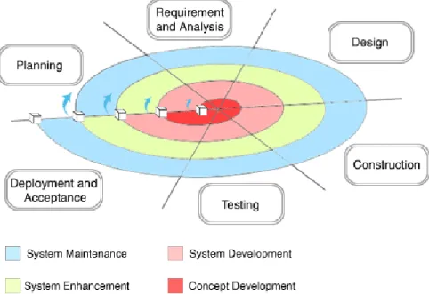
• The spiral model is defined in 1986 by Barry Boehm [9]. The principle of this approach (Figure 2.2) is to combine advantages of both top-down and bottom-up methodologies using incremental refinement.
Figure 2.2: The spiral approach principal
tests. Such flexibility of development has proved a considerable gain of time to market while keeping an excellent quality of the product. The limitation of this methodology is the fact that it is impossible to estimate the duration of the project at an advanced stage, especially for complex applications.
• The V model represents a sequence of steps of the project life. As presented in Figure 2.3, the main requirements are placed at the left side and their associated validation procedures at the right side. This model is a mixture of the incremental approach used for the development steps and the spiral ap-proach used for the validation. This model is currently used in management, business, computer sciences and many other fields.
Validate
requirements
Verify
design
Requirements Engeneering System validation Requirements Engineering Application design Application verification System verification Coding Trace implementation Trace implementation
Figure 2.3: The V-Model principal
All the previously presented models continue to be used with the domination of the V-model. However, the continuously increase of applications complexity made designers think of new methods with high level of abstraction to master this complexity. In the following, we introduce the Electronic System Level Design as a methodology of conception at the system level.
2.3 Overview on the Electronic System Level Design conception method 15
2.3
Overview on the Electronic System Level Design
conception method
The term ESLD methodology appeared early 21st century in a semi-conductor
consulting Company called Gartner Dataquest [58]. This term has been later
formalized in 2007 by B.Bailey et. al in [3]. The principle is to set the conception problem of very complex applications in the highest possible abstraction level. This high level specification is then followed by High Level Synthesis (HLS) to automat-ically obtain a target implementation. There are two possible target architectures, software or hardware, summarized in Figure2.4 and explained below.
Precacterized circuits Prediffused circuits Custom circuits Sea of gates ASIC (Application Specific Integrated Circuit) Programmable circuit ASIP (Application Specific Instruction set Processor) Programmable
machine
FPGA EPLD PLA Custom Semi- Custom
Gate array DSP mC General processors DSP mC Multimedia processors Full Custom Standart cell VLIW RISC
Software
hardware
Figure 2.4: Hardware and software different targets
2.3.1
The software-oriented architecture
This architecture is based on the execution of statements on micro-processors in-cluded in architectures such as:
• general processor that we can find in any computer and it can be RISC (Re-duced instruction set computing) based on simplified instructions or Very
long instruction word (VLIW) based on more complex Instruction Level Par-allelism,
• DSP (Digital Signal Processor) which is a powerful processor designed for in-tensive computations,
• micro-controller which is a simple processor dedicated for specific simple ap-plications,
• multimedia processor used for video display, sound treatments etc,
• the ASIP (Application Specific Instruction-set Processor) which is a full custom processor dedicated for a specific application.
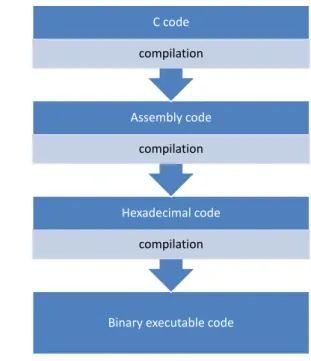
The advantage of using a processor is the use of very familiar and advanced lan-guages such as C, C++ or Java, which has a direct impact on the reduction of the development time. These languages allow also mastering very high complex ap-plications especially the object-oriented languages. To run a program on a software target it is necessary to achieve a certain number of compilations that enable moving from the specification language to a binary code understandable by the processors. For example, the execution of a C code follows the compilation of C into assembly code then hexadecimal code and finally the binary code (see Figure 2.5).
Binary executable code Hexadecimal code compilation Assembly code compilation C code compilation
2.3 Overview on the Electronic System Level Design conception method 17
Moreover, the algorithm implemented in a processor can be saved in a Read Only Memory (ROM), and almost all processors offer a way to flash this memory and put another application. This feature of software architecture is very important because it insures the flexibility and the re-usability of the target. Nevertheless, this type of circuits does have some drawbacks. They concern especially the energy consump-tion, the logical occupation and the performances. More precisely, a processor can never execute more than one instruction per cycle and so all statements are executed sequentially. Currently, some solutions of multi-core architectures are in progress but there is a major problem of scheduling statements into a set of processors with-out losing the global behavior of the application.
2.3.2
The hardware-oriented architecture
The hardware solution offers a circuit composed only of logical gates that execute basic functions directly with interconnected transistors. The revolution of hardware conception started by the appearance of languages such as VHDL and Verilog for the description of a circuit using lines of code. These languages were fist devel-oped for military purposes but they have been later standardized and published. A hardware circuit does not encapsulate a processor. Therefore, it is possible to design parallel treatments allowing very fast architecture solutions. Moreover, many opti-mizations can be automatically added to reduce the area occupation. The limitations of these circuits are especially about the development time and cost, the difficulty to design very complex applications and non re-usability of the targets. These limita-tions are getting resolved especially with the appearance of reconfigurable circuits explained below.
The physical execution of a software program is related to the compilation and the simulation of a software language (C or Java for example) on its associated com-piler. However, for hardware, things are different. The hardware implementation is finally a VHDL or a Verilog code that is going to be synthesized into a lower level code in the Register Transfer Level (RTL) that can be later transformed into transis-tors connections as presented in Figure 2.6 where we present the different steps of the implementation generation of an addition block.
The RTL level is a representation of the behavior using basic operations (addition, assign ...). This level very strategic and important because when the behavior is correct the derived circuit implementation is also correct. From this level, it is just necessary to realize the placement and Root (P&R) in the target architecture. So how to get a circuit with that code? For this purpose and as presented in Figure 2.7, hard-ware compilers use a library of components that allow describing any RTL (Register Transfer Level) component into a connection of logical gates and this step is called the logic synthesis. Finally, gates are automatically transformed into a connection of transistors transformed by the Silicon compiler into a mask pattern.
SUM := A1+B1
Algorithm RTL Gates
Transistors
+
Figure 2.6: The hardware conception evolution of an addition operation block
The mask pattern is used in the Silicon foundry to create an ASIC (Application Spe-cific Integrated Circuit) using microscopic silicon doping and etching techniques. The ASIC is the most custom hardware architecture. However, the foundry cost of ASICs creation is very high and this finding used to be the main drawback of hardware generation until the advent of the programmable circuits such as SPLD (Simple Programmable Logic Device), CPLD (Complex Programmable Logic De-vice) and the most recent FPGA (Field-Programmable Gate Array).
I The SPLD This family is one of the oldest and most basic programmable technologies. It contains architectures such as the PAL (Programmable Array logic), GAL (Generic Array Logic), PLA (Programmable Logic Array) and PLD (Pro-grammable Logic Device). They are the smallest and the cheapest pro(Pro-grammable logic which present simple operations such as sum and product. Their technology is similar to the PROM one. The SPLD uses fuses such as PROM to describe the logical operations which makes them non-re-programmable.
IThe CPLD The CPLD extended the PLD concept to a higher integration level for a better system performance. It represents the equivalent of the connection of 2 to 64 SPLDs. The logical blocks communicate via programmable inter-connections presented as a matrix of programmable switches. The transistor technology usually
2.3 Overview on the Electronic System Level Design conception method 19
The mask pattern Physical level
Silicon compilation
Logic level
Physical synthesis
RTL level (Register transfer description)
Logical synthesis
Behavioral level (VHDL or Verilog)
RTL synthesis
Figure 2.7: The hardware conception flow from VHDL or Verilog programs used is the CMOS and the memory cells are EPROMs EEPROMs or Flash. The CPLD present many advantages such as:
• possible integration of complex operations,
• constant and consequently predictable propagation time,
• their macro-cells have more inputs than outputs which makes them apt for decoding operations and FSM implementations.
They also present drawbacks as: • slow programming time,
• limited programming instructions,
• designers have to disconnect the component from the card to program the appropriate hardware.
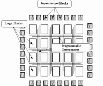
I The FPGA This is the most sophisticated programmable circuits and they continue their progress thanks to the Altera and Xilinx semi-conductor companies. An FPGA is composed of logical blocks, input/output blocks and programmable inter-connections as presented in Figure 2.8. New FPGAs may contain integrated memory cells and PLL blocks (Phase-Locked Loop).
Figure 2.8: General architecture of an FPGA
The main logical blocks of an FPGA are the LUTs (Look-Up Tables) that allow the implementation of any truth table of a logical function. Every function generator behaves as a little ROM which output is selected by the input signal. The realization
of a logical function with N variables requires 2N configuration bits. As presented
in Figure 2.9, a multiplexer is used later to select an output from the configuration memory.
With LUTs, we can find FPGAs with DSP blocks to perform multiplication opera-tions.
To make the connections between the matrix of LUTs for example, the FPGAs are equipped with a memory that transforms a specific program called Netlist into a set of signals that control the inter-connections to make any wanted circuit. This prop-erty is very interesting since it allows the prototyping of hardware circuits before looking for Silicon foundries. The FPGA has revolutionized the world of hardware implementations and recently the software implementations. Indeed, new FPGA cards are able to integrate several embedded processors and to connect them to hardware components. For example Xilinx Company provides its tools and cards customers with processors such as Power PC or Micro Blaze. Altera Company allows users to implement software component using the NIOS processors. Re-searchers and industrials are now using the reconfigurable aspect of FPGAs using
2.3 Overview on the Electronic System Level Design conception method 21
Configuration
memory
MUX
Inputs Output
Figure 2.9: LUT architecture principle
multi-Netlist components which internal behavior change completely every config-uration clock period. This reconfigconfig-uration frequency is increasing and passing over 200MHz which means 200 million circuits every second. The reconfigurable aspect is strongly related to the RVC standard, the main context of this thesis.
2.3.3
The Hardware Software Codesign
It is clear that the hardware and software architectures have both advantages and drawbacks, as summarized in Table 2.1.
Hardware Software
Performances + −
Logic occupation + −
Energetic efficiency + −
Development time and cost − +
complexity management − +
Flexibility − +
Table 2.1: Advantages and drawbacks of HW and SW architectures
Thus, an alternative to these two approaches have been later proposed: the Hardware Software Codesign (HSC) as an alternative trying to combine both ar-chitectures and exploit their advantages. The first attempts of HSC faced a major
problem of data communication. Indeed, software designers conceived the pro-cessors and hardware designers developed the hardware IPs separately, and they finally made the connection. Such conception flow is very time consuming due to communication and synchronization problems that involve many feedbacks. The solution was to unify the programming language and/or the conception platform [69]. For that purpose, SystemC was introduced as an extension of the famous C language to support hardware structures such as concurrent threads or new types (time, bit, bit vector, logic etc.). This solution was followed by original methods such as Dataflow programming with new languages and platforms to generates mixed architectures. Test and validation platforms followed this evolution. Such well known design environments and simulators are Ptolemy [12], Vulcan [65], Cosyma [28], SynDEx, GCLP, COSYN etc. These infrastructures and platforms re-solved many codesign limitations. However, the main limitation persisting is the Design Space Exploration (DSE). This codesign step consists of choosing which pro-cess is going to be implemented in hardware, and which one is going to be imple-mented in software. Theoretically, in the first hand, a control based algorithm that contains many statements such as If, While or For, should be developed in software because a For loop is executed sequentially and can never be parallelized. So there is no gain to use hardware for that, while a processor can execute it. On the other hand, in supercomputing, algorithms just execute very intensive computations with logical and arithmetic operators. In that case, a hardware architecture would offer very fast circuits. Nevertheless, things are not in practice as easy because the system implies more constraints. For example, if we consider a process P1 with intensive computations that sends data to a process P2 consuming that data and executing a control-based algorithm, then we speak about two strongly linked processes (Figure 2.10). The fact of implementing P1 in hardware and P2 in software has no sense be-cause, whatever the execution rapidity of P1, the output of P2 depends only on the execution frequency of P2. Consequently, it could be easier to merge both processes into the same software algorithm.
This is not the only problem to mention since many other communication limita-tions persist. Sometimes, in the same type of architecture, there may be a conflict for example a software task may be executed by a Digital Signal Processor (DSP), a micro-controller, a multi-core platform etc. The compromise flexibility VS per-formance is not easy the resolve manually. Many automatic tools were developed to automatically explore the design space and try to find the best compromise, but current results are not considered enough satisfying.
2.4 High Level Synthesis (HLS) from high level to RTL level 23
P1
P2
P3
P4
P5
SW P1,P2 HW P3,P4 HW P5Figure 2.10: Space exploration of the design
2.4
High Level Synthesis (HLS) from high level to RTL
level
The role of High Level Synthesis (HLS) tools is to transform a behavioral description (code or algorithm) into a Register Transfer Level (RTL) description. This synthesis realizes the assignment of the circuit functions to the operators so called resources, the connection between these operators and the moment each operation is executed during time intervals (called “control steps”). The synthesis can be done with two main exclusive considerations: a minimum of surface consumption or a maximum
of execution speed. Let us consider a simple operation of Y = A+B+C+D. In the
first case, the synthesis tool is going to look for the minimum of processing blocks and create the necessary scheduling to have the correct result after a set of control steps. Figure 2.11 presents one possible implementation in which one addition block is created.
The behavior is the following: a decoder in the scheduler fixes the multiplexer so
that the first output is B and so the result of the addition block is A+B. The next
control step, the MUX outputs the C and finally D. Every addition result is stored in the buffer so that the next operation is performed between the old result and
the new value. After the necessary time, the result in Y is exactly A+B+C+D.
A B D C Y
+
Buff er MUX SchedulerFigure 2.11: HLS with limited area constraint
result to be used for the rest of the application. It is also possible to parallelize the operations in case of data independence as presented in Figure 2.12.
A B D C Y
+
+
+
Figure 2.12: HLS with unbounded area and parallelism
The evolutions of HLS started with research tools that tried to explore a max-imum of generation concepts. Later, industrials such as Mentor Graphics or Syn-opsys were involved but their results were not satisfying for most users because the generated code is a very low-level one, hard to debug or to optimize. After a combined effort between researchers and industrials, the third generation of tools was more successful and it is currently increasing in the market. These tools are discussed in the next section.
2.5 Existing HLS tools 25
2.5
Existing HLS tools
Currently, the most famous HLS tools used by industrials are Catapult-C from Men-tor Graphics [57], C-To-Silicon from Cadence, Symphony-C from Synopsys [75] and C2H from Altera [50], [61]. In the research field, we cite the tool GAUT [18], [17] in development in the Sticc-lab. These tools, especially the industrial ones, can gen-erate excellent implementations from high level specification. However, the main limitation is that they cannot handle with a complete system. A partial generation applied on a simple functional block is possible but when the system gets complex, none of these tools is able to generate a correct implementation. This limitation is due to the fact that these tools take sequential codes such as C as an input. The C lan-guage has been conceived for sequential process and not hardware one. The extrac-tion of parallelism from a code developed with a sequential philosophy can never be optimal, the generated code also. Moreover, such tools cannot accept all kinds of C code. They put many restrictions on how the C has to be written (pointers, constants, functions and main declaration). In fact, if the user intends to generate an implementation for a large application such as MPEG-AVC decoder, he is going to spend a large amount of time refactoring the code to match the specifications of the tool.
Considering this fact, new axes of research are currently oriented to the use of Domain specific Languages (DSL) that substitute C, VHDL, SystemC etc. These lan-guages are associated with advanced design environments dedicated for codesign. In this thesis, we adopted the Cal Actor Language (CAL) and its associated com-pilation infrastructure for the generation of hardware and/or software implemen-tations. This choice is explained by the fact that the CAL associated infrastructures are able to manage a complex system such as MPEG-4 Simple Profile decoder which implementation work is presented in [40]. In addition, all the tools used for graph edition, compilation and pretty printing are Open-source.
2.6
Conclusion
This chapter Introduced the Electronic System Level Design methodology. First, we presented the state of the art of the methods used for digital signal processing. These methods are not very efficient to manage the conception of a full complex applica-tion in the system level. For this reason, the ESLD is introduced as an alternative conception methodology. This methodology has to be followed by a High Level Synthesis to obtain the Register Transfer Level. Therefore, we presented the HLS techniques and a set of existing HLS tools for automatic generation of implementa-tions from high level languages.
This work is located in the framework of the ESLD. Indeed, the main contri-butions of the thesis focused on finding solutions for hardware generation from
Dataflow programs. Before explaining these contributions in Part II, next Chapter introduces the Reconfigurable Video Coding standard and Dataflow compiling in-frastructures.
RVC: methodology and framework
3.1 MPEG RVC standard . . . . 30 3.2 RVC-CAL language . . . . 35 3.3 RVC Models of Computation . . . . 42
3.3.1 Overview . . . 44
3.3.2 The Dataflow Process Network MoC and derived MoCs . . 46
3.4 Compilation and simulation of RVC-CAL designs . . . . 52
3.4.1 RVC-CAL compilation . . . 53
3.4.2 Generation of HW/SW implementations with OpenDF . . . 56
3.4.3 Open RVC-CAL Compiler (Orcc) . . . 58
3.5 Hardware compilers limitation: the multi-token case . . . . 65 3.6 Conclusion . . . . 66
29
In 1984, the CCITT, known currently as ITU Telecommunication Standardization Sector (ITU-T), published the first digital video decoder as H.120 based on the ”COST 211” project of the Queen Mary University of London. H.120 proposed several coding methods like scalar quantization, variable length coding, differential pulse code modulation and conditional replenishment. Some advanced compres-sion methods like motion compensation and background prediction were added in 1988. The spatial resolution results were quite satisfying but temporal performance was poor. The limitation of this codec is that it applies most algorithms using a pixel-per-pixel scan which led to the solution of block-based codecs such as H.261, considered as the pioneer of practical video coding. Later, and since the beginning of ISO/IEC/WG11 (MPEG) in 1988 with the advent of MPEG-1, many video codecs have been developed (MPEG-4 part2, MPEG-4 AVC, MPEG-4 SVC, HEVC etc.) as presented in Figure 3.1. 1980 1985 1990 1995 2000 2005 2010 2015 0 2 4 6 8 10 12 14 H.120 H.261 MPEG-1 MPEG-2 H.263 MPEG-4 part 2 H.264 Theora VC-1 SVC MVC VP8 High Efficiency Video Coding
Video standards Year of publication N u m b e r o f s ta n d a rd s p u b lis h e d
Figure 3.1: Video codecs timeline
These codecs are increasing in complexity since they proposed advanced meth-ods for texture and motion coding and so they require larger design time. Conse-quently, it became a tough task for standard communities to develop, test and stan-dardize a decoder at any given time. In addition, every standard has a set of coding techniques depending on the implementation target or the user specifications (pro-fessional or consumer) so it is not possible to implement all of them in the same
coder. That is why, standards define some algorithm subsets so called ”profiles”. A profile may encapsulate another profile or they can be completely different.
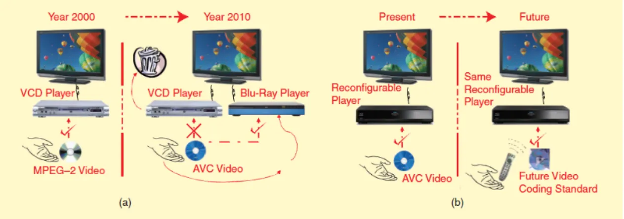
Moreover, all the previously presented standards are developed in a monolithic way making it harder to generate hardware implementations, and also to reuse or update some existing algorithms. Indeed, several standards are sharing many al-gorithms like a Discrete Cosine Transform (DCT) [1] or quantization but these com-monalities can neither be directly exploited at the specification step, nor at the low level implementation one because of the monolithic structure of algorithms. Conse-quently, the whole old standards have unfortunately to be substituted by the new ones which involves also to change the player device. Such a change involves a costly replacement of users decoding multimedia devices to follow the evolution of the standards which is annoying for both users and professionals (Figure 3.2(a)). These facts originated a new conception methodology standard called Reconfig-urable Video Coding (RVC) introduced by MPEG. Unlike all the other MPEG stan-dards, RVC does not standardize algorithms to encode data but instead it standard-izes the way an algorithm has to be written to conserve an independent behavior and consequently the re-usability. Thus, whatever the future video coding standard, the same multimedia support is able to decode the information as presented in Fig-ure 3.2(b). MPEG-RVC principles and main notions are detailed in the following Section.
Figure 3.2: Objective of the MPEG RVC standard
3.1
MPEG RVC standard
The MPEG-RVC framework is an ISO/IEC standard under development aiming at replacing the monolithic representations of video codecs by a library of components. For that reason RVC is based on two standards:
3.1 MPEG RVC standard 31
IISO/IEC23001-4 or MPEG-B pt. 4 [37] which defines the framework and the standard languages to develop any RVC decoder.
IISO/IEC23002-4 or MPEG-C pt. 4 [38] which represents the set of employed tools.
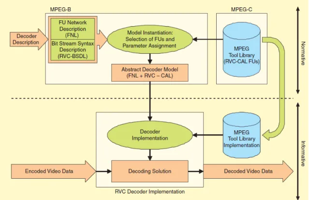
As presented in Figure 3.3, MPEG-B is used to transform a decoder description into an abstract decoder model designed with the standardized languages (algo-rithms and network). It possible to use algo(algo-rithms defined in the tool library of MPEG-C. This standard description represents the normative part. In the infor-mative part, compilation solutions are used to transform the RVC design into an implementation that represents the decoding solution.
Figure 3.3: RVC framework components
RVC presents a modular library of elementary components (actors). The most important and attractive features of RVC are reconfigurability and flexibility. An RVC design is a Dataflow directed graph with actors as vertices and unidirectional FIFO channels as edges. An example of a graph is shown in Figure 3.4. This figure is an RVC description of MPEG-4 AVC decoder. The directed graph contains actors
(demux, select, add), FIFO channels (such as the FIFO x between select and add) and also directed graphs that contain actors and FIFO channels (texture decoding, intra predictions ...). Every directed graph executes an algorithm on sequences of tokens read from the input ports (mv, mb type, coe f ) and produces sequences of tokens in the output ports (out).
INTER_P Prediction INTRA_16x16 Prediction INTRA_4x4 Prediction Select MV RD PRED PRED PRED X0 X1 X2 X RD RD
COEF Texture decoding
Deblocking Filter MBType MV MB OUT COEF MBType Decoded Picture Buffer MBType MV MB RD OUT OUT Add X Y Z Demux MbType X0 X1 X2 X MBType MV MBType Prediction modes
Figure 3.4: Graph example: Dataflow diagram of the MPEG-4 part 10 AVC decoder Actually, defining several implementations of video processing algorithms using elementary components is very easy and fast with RVC since every actor is com-pletely independent from the rest of the other actors of the network. Every actor has its own scheduler, variables and behavior. The only way of communication of an actor with the rest of the network are its input ports connected to the FIFO chan-nels to check the presence of tokens. Then, an internal scheduler enables or not the execution of elementary functions called actions depending on their corresponding firing rules (see Section 5.3). Thus, RVC insures concurrency, modularity, reuse, scal-able parallelism and encapsulation. In [40] Janneck et. al. shows that, for hardware designs, RVC standard allows a gain of 75% of development time for hardware design compared to existing HDLs, and also considerably reduces the number of lines of code. To manage all the presented concepts of the standard, RVC presents a framework based on the use of:
• RVC-CAL a subset of the CAL actor language called RVC-CAL that describes the behavior of the actors (detailed below in Section 3.2).
• FNL a language describing the network called FNL (Functional unit Network Language) that lists the actors, the connections and the parameters of the network. FNL is an XML dialect that allows a multi level description of actors hierarchy. It means that a functional unit can be a composition of other functional units connected in another network. For the network example of Figure 3.5, we have 3 actors data, process and storage with simple connections using two FIFOs. The FNL code is presented in Figure 3.6.
3.1 MPEG RVC standard 33
Data
o1 i1Process
o2 i2Storage
Figure 3.5: RVC network example
1 < XDF n a m e =" E x a m p l e " > 2 < I n s t a n c e id =" P r o c e s s " > 3 < C l a s s n a m e =" A l g o _ p r o c e s s "/ > 4 </ I n s t a n c e > 5 < I n s t a n c e id =" D a t a " > 6 < C l a s s n a m e =" A l g o _ D a t a "/ > 7 </ I n s t a n c e > 8 < I n s t a n c e id =" S t o r a g e " > 9 < C l a s s n a m e =" A l g o _ S t o r a g e "/ > 10 </ I n s t a n c e > 11 < C o n n e c t i o n dst =" D a t a " dst - p o r t =" o1 " src =" P r o c e s s " src - p o r t =" i1 "/ > 12 < C o n n e c t i o n dst =" P r o c e s s " dst - p o r t =" o2 " src =" S t o r a g e " src - p o r t =" i2 "/ > 13 </ XDF >
Figure 3.6: FNL code of Figure 3.5
• BDL bitstream Syntax Description Language (BSDL) [41, 55] to describe the structure of the bitstream.
• VTL an important Video Tool Library (VTL) of actors containing MPEG stan-dards. This VTL is under development and it already contains 3 profiles of MPEG 4 decoders (MPEG-4 part 2 Simple Profile, MPEG-4 part 10 Progressive High Profile and MPEG-4 part 10 Constrained Baseline Profile).
• Tools around RVC for edition, simulation, validation and automatic genera-tion of implementagenera-tions:
- OpenDF framework [7]: is an interpreter infrastructure for the simulation of hierarchical actors network.
- OpenForge: is a hardware compiler called OpenForge1[34] to generate HDL
implementations from RVC-CAL designs.
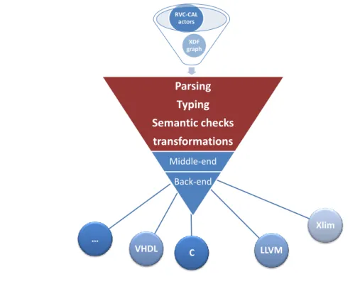
- Open RVC-CAL Compiler (Orcc)2 [41]: Orcc is an RVC-CAL compiler
un-der development. It compiles a network of actors and generates code for both hardware and software targets. Orcc is based on works on actors and actions analysis and synthesis [67, 81]. In the front-end of Orcc, RVC-CAL actors are parsed into an abstract syntax tree (AST), and then transformed into an inter-mediate representation (IR) that undergoes typing, semantic checks and sev-eral transformations in the middle-end and in the back-end. Finally, a code generation process is applied on the resulting IR to generate a chosen imple-mentation language (C, Java, XLIM, LLVM etc.).
IThe importance of RVC-CAL At this level, the question is: why RVC-CAL
and not C? Actually, a C description involves not only the specification of the algo-rithms but also the way inherently parallel computations are sequenced, the way data are exchanged through inputs and outputs, and the way computations are mapped. Recovering the original intrinsic properties of the algorithms by analyzing the software program is impossible. In addition, the opportunities for restructur-ing transformations on imperative sequential code are very limited compared to the parallelization potential available on multi-core platforms. For these reasons, RVC adopted the CAL language for actors specification.
IThe reconfigurable aspect of RVC-CAL The previously presented aspect of RVC is the automatic generation of hardware and software implementations using compilation infrastructures like OpenDF or Orcc. Another very important aspect of the standard is the reconfigurability. Indeed, the RVC representation of a decoder clears interoperability problems between algorithms providers and receivers. It is also possible to use proprietary Video Tool Libraries containing functional units that are not specified in MPEG-C part 4. Thus, it is possible to apply run-time dynamic reconfigurations just by modifying the topology of the network. Indeed, all MPEG decoders are based on the same hybrid decoding schemes including intra and inter predictions with more or less actors. The objective of MPEG-B part 4 is to provide a decoder for any bitstream coded with RVC specification using this specification, the hybrid decoder and actors from the VTL of MPEG-C and the proprietary VTL
1Available at http://openforge.sf.net
3.2 RVC-CAL language 35
of the intended decoder as presented in Figure 3.7. The modular representation of networks facilitates such operation.
Proprietary VTL
Standardized VTL
(MPEG-C)
MPEG-C decoder Proprietary decoder Hybrid decoder RVC decoder specification Bitstream Decoded videoFigure 3.7: Reconfigurable principle of RVC
3.2
RVC-CAL language
RVC-CAL is a language standardized by MPEG as part of the RVC standard, and it is a restricted subset of the CAL Actor Language that was created in the Ptolemy II Project [11] by Janneck and Eker who detailed the rationale of the language in the CAL white paper [27] and the technical report [26]. In the following, we present the main notions of RVC-CAL:
I Global structure of an actor An RVC-CAL code is the description of func-tional unit called ”actor”. Like the notion of ”Entity” in hardware development, an actor definition begins with a header containing the specification of a box in a macroscopic way by presenting the name of the actor, parameters, ports (inputs and outputs) and their types. Figure ?? presents an actor called ”example” with a
parameter ”m” of type integer, two input ports ”IN1” and ”IN2” of type integer coded on 8 bits and one output port ”OUT” of type integer coded on 13 bits.
1 a c t o r e x a m p l e (int m )
2 int ( s i z e=8) IN1 , u i n t ( s i z e=12) IN2 = = > int( s i z e=13) OUT :
3
4 // a l g o r i t h m
5 6 end
Figure 3.8: RVC-CAL actor header
The execution of an RVC-CAL code is based on the exchange of data tokens between actors. Each actor is independent from the others since it has its own parameters and finite state machine if needed. Actors are connected to form an application or a design, this connection is insured by FIFO channels. Executing an actor is based on firing elementary functions called actions. This action firing may change the state of the actor. An RVC-CAL Dataflow model is shown in the network of Figure A.1.
FIFO Actor
Consume/produce tokens FIFO
Consume/produce tokens and modify internal states
FIFO
Actions
State Actor Actor
Actions are implemented sequentially and they can be sequenced
FIFO
Actor
be sequenced
FIFO
Figure 3.9: CAL actor model
Figure ?? presents an example of a CAL actor realizing the sum between two tokens read from its two input ports.
In the “sum” actor, the internal scheduler allows action “add” only when there is at least one token in the FIFO of port “INPUT1” and one token in the FIFO of port “INPUT2”. This unique dependency from the presence of data in the FIFOs explains the fact that an actor can neither read nor modify the state of any other actor.
IVariables Before starting the micro-definition of an actor process, it is pos-sible to declare state variables that may be shared by all the actions of this actor.
3.2 RVC-CAL language 37
1 a c t o r sum ()
2 (int s i z e=8) INPUT1 , (int s i z e=8) I N P U T 2 = = > int( s i z e=8) O U T P U T:
3 4 add: a c t i o n I N P U T 1:[ i1 ] , I N P U T 2:[ i2 ] = = > O U T P U T:[ s ] 5 var 6 int s 7 do 8 s: = i1 + i2 ; 9 end 10 end
Figure 3.10: Example of sum actor
Of course, actions may have their own local variables. As presented in Figure 3.11, variables may be integers (line 1), unsigned (line 2), boolean (line 3) or lists (line 4). A list in CAL is an array of elements of the same type (int, uint or bool). As it is intended for both hardware or/and software implementations, it is necessary to specify the exact dynamic of variables and ports (line 5).
1 int v a r 1 : = 0; 2 u i n t v a r 2 ;
3 b o o l v a r 3 : = t r u e ;
4 L i s t ( t y p e:int, s i z e = 10) v a r 4 ; 5 int ( s i z e=12) v a r 5 ;
Figure 3.11: Example of variables declaration
I Expressions Like any programming language, RVC-CAL uses a set of ex-pressions that can be mathematical (Figure 3.12.line 1) or binary (Figure 3.12.line 2). The only restriction is that these expressions are side-effect free which means that they are idempotent, and consequently they cannot change the value of external el-ements like state variables.
1 x: = a + 5; 2 y: = a & 7;
Figure 3.12: Examples of expressions in RVC-CAL
Expressions are used to form the statements of an algorithm. RVC-CAL presents five types of statements:
• The assignment: an expression may be assigned to a variable (local or global). It is also possible to assign it to a list index in case of lists.
• The call: this statement is used when functions or procedures are used in the algorithm. The call of a function is accompanied with an assignment of the result of this function to a state or local variable.
• The While loop: for an unknown or infinite number of executions. The loop continues the execution while a conditional expression is true.
• The foreach loop: for a finite number of executions.
• The ”if .. then .. else”: for a conditional execution of the statements.
I RVC-CAL action An action represents the microscopic representation of the behavior. Every action is related to a firing rule which is the rule that specifies the necessary conditions that allows the action to be executed. These conditions represent the schedulability and they concern especially the number of available
tokens in the input FIFOs. Other conditions on the value of input tokens or
the value of a state variable may be added using the ”guard” instruction. The importance of this additional condition is that it is tested before consuming data from the FIFOs. As shown in Figure 3.13, the firing rule is presented in the header of the action followed by the body. The header may also contain the declaration of local variables.
Scheduling condition
1 a c t i o n _ n a m e: a c t i o n IN1:[ in1 ] , IN2:[ in21 , i n 2 2 ] = = > OUT:[ o ] 2 var 3 int o : = 0 4 g u a r d 5 in1 > 0 , 6 i n 2 1 = c o u n t e r Body 12 doo : = c o u n t e r +1; 3 end
Figure 3.13: Action main parts: scheduling condition and body
To be executed, the action of Figure 3.13 has to satisfy the scheduling condition of: presence of one positive token at least in the FIFO of Port ”IN1”, two tokens in the FIFO of port ”IN2” such as the first of them equals the value of a state variable ”counter”. When the scheduling conditions are true, the action consumes the 3 tokens from the FIFOs, executes the body and outputs the value of ”o” in the FIFO of port ”OUT”. Now, if we substitute the guard condition by a conditional block, the algorithm becomes:
1 a c t i o n _ n a m e: a c t i o n IN1:[ in1 ] , IN2:[ in21 , i n 2 2 ] = = > OUT:[ o ] 2 do
3 if in1 > 0 && i n 2 1 = c o u n t e r
3.2 RVC-CAL language 39
5 o : = c o u n t e r + 1; 6 end
7 end
In this case, the presence of tokens is enough to fire the action which means that the three tokens are already consumed before the ”if” test. If the ”if” condition is false, the action is not going to execute any statement and the output in the port ”OUT” will be the old value of the variable ”o”. The consumed tokens cannot be used anymore by any another action.
I Functions The body of an action or even the ”guard” condition may call a set of expressions located in a function. The function is considered as an expression which type is the type of its return. Consequently, it is also side-effect free. A function header (line 1 of Figure 3.14) presents the tag, the parameters and the type of the result; then follows the body containing the algorithm.
1 f u n c t i o n d i v r o u n d n e a r e s t (int i , int i D e n o m ) - - > int :
2 if ( i > = 0) t h e n 3 ( i + ( i D e n o m > > 1)) / i D e n o m 4 e l s e 5 ( i - ( i D e n o m > > 1)) / i D e n o m 6 end 7 end
Figure 3.14: Example of a function in RVC-CAL
I Procedures Concerning the procedure and like many other imperative languages, it represents a set of side-effect instructions that can be called at any time by an action or a function or another procedure. The RVC-CAL code of a procedure has the form shown in Figure 3.15.
1 p r o c e d u r e p r o c e d u r e _ t a g ( p a r a m e t e r s ) 2 b e g i n
3 // i n s t r u c t i o n s
4 end
I Actions priority The behavior of an actor is managed by a global action scheduler that detects the schedulability of all actions and allows the firing of the ac-tion which firing rule is true. Nevertheless, it is possible to have two or more schedu-lable actions at the same time and the question is which action will be allowed by the global scheduler? If the choice is random, we will have a non-deterministic behav-ior of the actor. For this purpose, the notion of prbehav-iority has been added to RVC-CAL using the following structure of Figure 3.16:
1 p r i o r i t y
2 a c t i o n 1 > a c t i o n 2 ;
3 a c t i o n 3 > a c t i o n 4 > a c t i o n 2 ; 4 end
Figure 3.16: Example of a priority in RVC-CAL More details are presented in section 5.3.
I Finite state machine (FSM) For more complex actors, RVC-CAL offers the possibility to use an FSM scheduler to add more restrictions on the actions that can be scheduled at a given state. An FSM has an initial state and every state presents a set of actions that may let the actor in the same state or that may change the actor state. In case of conflicted actions in the same state, it is necessary to add a priority. Figure 3.17 shows an RVC-CAL declaration example of an FSM that can be represented graphically by the schema of Figure A.3 where states are presented with vertices and the transitions with edges. This type of representation will be adopted for the rest FSM related figures.
1 s c h e d u l e fsm i n i t _ s t a t e: 2 i n i t _ s t a t e ( a c t i o n 1 ) - - > s t a t e 1 0 ; 3 s t a t e 1 0 ( a c t i o n 2 ) - - > s t a t e 1 0 ; 4 s t a t e 1 0 ( a c t i o n 3 ) - - > s t a t e 1 1 ; 5 s t a t e 1 1 ( a c t i o n 4 ) - - > i n i t _ s t a t e ; 6 end 7 8 p r i o r i t y 9 a c t i o n 3>a c t i o n 2 ; 10 end