HAL Id: hal-01007525
https://hal.archives-ouvertes.fr/hal-01007525 Submitted on 30 Oct 2019
HAL is a multi-disciplinary open access archive for the deposit and dissemination of sci-entific research documents, whether they are pub-lished or not. The documents may come from teaching and research institutions in France or abroad, or from public or private research centers.
L’archive ouverte pluridisciplinaire HAL, est destinée au dépôt et à la diffusion de documents scientifiques de niveau recherche, publiés ou non, émanant des établissements d’enseignement et de recherche français ou étrangers, des laboratoires publics ou privés.
Numerical Model: Simplified Strategies for Vulnerability
Seismic Assessment of Existing Structures
Cédric Desprez, Panagiotis Kotronis, Stéphane Grange
To cite this version:
Cédric Desprez, Panagiotis Kotronis, Stéphane Grange. Numerical Model: Simplified Strategies for Vulnerability Seismic Assessment of Existing Structures. P. Guéguen. Seismic Vulnerability of Struc-tures, ISTE - Wileys Pubs, pp.213-247, 2013, 978-1-84821-524-5. �10.1002/9781118603925.ch5�. �hal-01007525�
N uinerical Model: Si�nplified
Strategies for Vulnerability Seisinic
Assessinent of Existing Structures
Cedric DESPREZ, Panagiotis KOTRONIS and Stephane GRANGE.
5.1. Introduction
The seismic response of structures is the result of a strong interaction between the "material" effects (local nonlinearity), the "structural" effects (geometry, distribution of mass and boundary conditions) and environmental effects (soil structure interaction). Two approaches are often used to take these phenomena into account: the "simplified" and the "full".
The "simplified" approach is an intermediary approach where, generally, the kinematic field (displacement, velocity and acceleration) is described by the displacements and the rotations at the nodes of a bar, a beam, a plate or shell elements, whereas all information concerning the behavior of the materials is processed at a global or local level inside the element. More specifically we distinguish:
1) The use of bar elements that work only in compression and traction. In the case of masonry walls, models associated with two bar elements [STAF
63,
MAl 71, DAW 89, ELO 91, DUR 94, COM 00] or more than two [ELD 03] have been developed. The bar elements have the mechanical properties of masonry, such as a Young's modulus, the Poisson ratio and the resistance in compression. Among the methods used for the design of reinforced concrete structures we note those inspired by the "truss" method [RIT 99, MOR 20] and, more specifically, the compression field theory [COL 78] and the method known as the rotating-angle softened truss model [H8U 88]. These lasts methods have shown the importance of knowing the direction of principal axes just before cracking.The problem of the methods presented above is the need to estimate the two-bar geometric properties, especially the width (section). Empirical equations are often proposed, based on the "full" experimental or numerical simulations (see hereafter). An idea to solve this problem is to use truss and/or beam frames as an equivalent of a continuous elastic media [HRE 41, ABS 72]. Coupled with constitutive laws based on the damage and plasticity theory, this method has shown its efficiency for seismic vulnerability assessment of existing structures made up of reinforced concrete or masonry walls [KOT 00, MAZ 02, KOT 03, KOT 05a,
SAM 11] .
2) The use of beam elements for which the usual displacement and strains field assumptions (N a vier Bernoulli or Timoshenko) are often adopted. The integration of the rheological material model is made with a classical numerical integration along the length of the beam or in the transversal directions of the cross-section. This last kind of element - called a "multi-fiber" - is powerful for a complex nonlinear analysis of composite structural elements, and in the case of reinforced concrete elements [PEG 94, GUE 94,
SPA 96, PET 99, KOT 00, MAZ 04, KOT 05a, KOT 05b, MAZ 06, KOT 08, CER 07, GRA 09c, PAP 10, CAl 13] . In the case of concrete reinforced with a composite, the presence of reinforced frames is not specifically introduced, but their effects are generally taken into account by the possibility of introducing into the concrete constitutive law a possible confinement effect.
3) The use of "global" constitutive laws that describe the glo hal behavior of a structure or part of a structure. They usually give a relationship between generalized deformations and their related generalized forces without using local constitutive laws [FAR 91, POL 98, COM 01] . Two-dimensional (2D) or three-dimensional (3D) elements can be developed using global variables (forces and displacements), according to the plasticity theory. On the basis of the concept of macro-elements [NOV 91] they are particularly convenient for reproducing the behavior of rigid shallow foundations lying on a solid semi-infinite medium. This approach allows us to significantly reduce the computational cost of the simulations [GOT 99, CRE 01, CRE 02, GRA 08a, GRA 08b, GRA 08c, CHA 09, GRA 09a, GRA 09b, CHA 11, GRA 11].
The "full" approach consists of using a combination of a geometric model (2D or 3 D meshes), constitutive laws (in 2D or in 3D) and a model for simulating the loading. It enables the simulation of complex problems such as strain localization, the opening and spreading of cracks and structure response until failure [COM 00, ILE 00]. This approach is difficult to use and requires experience and versatility from the engineer and does not enable a systematic use for structure analysis.
In this chapter, the seismic vulnerability of an existing structure (a building located in the Grenoble area, France) will be studied using multi-fiber beams and constitutive laws based on the damage mechanics and plasticity.
5.2. Case study
5.2.1. Presentation of the structure
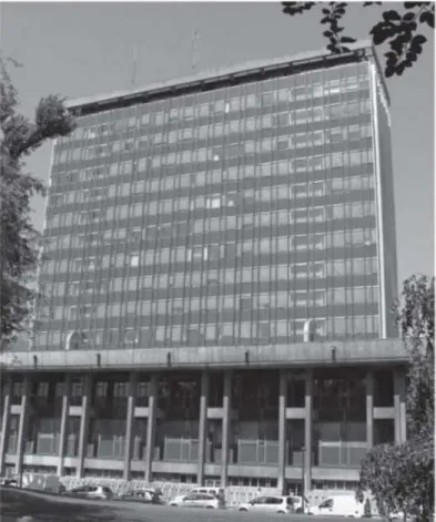
The building (Figure 5.1) is composed of two main structures made up of reinforced concrete, the tower and the basement structure, which is around it. The vulnerability analysis focuses, in this work, on the tower without interaction with the adjacent structure as they are separated by a dilatation joint. In the following sections, we will refer to the tower structure as the "tower".
Figure 5.1. General view of the building
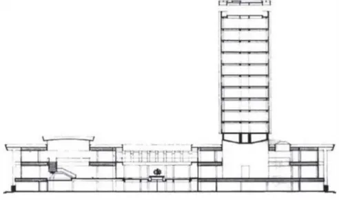
The tower (52 m tall) has an underground level, an entrance hall at ground level and six standard stories covered by a roof level at the top (Figure 5.2). Its surface is about 43 m in length (north-south direction) and 13 m in width (east-west direction). The main structural frame is composed of four columns containing the staircase and the lift, and slabs lying on a framework of beams and bars.
Figure 5.2. Building elevation
One particular aspect of the structure is the entrance hall on the ground floor that is composed only of the main columns. All the upper stories of the tower are lying on a prestressed concrete caisson element linked with the columns and making a portal frame. The last story of the tower is not designed with the same geometry as the others. This story is essentially made with thin reinforced concrete walls.
The structure is equipped with a permanent instrumentation able to detect the vibrations due to ambient noise [MIC 10]. This system allows determining the dynamic signature of the structure such as its natural in situ
characteristics (fundamental frequencies and modes, etc.) with regard to weak stresses (wind, earthquakes, etc.).
5.2.2. Spatial discretization
The building is modeled with the finite element code Cast3m (http://www-cast3m.cea.fr/). Multi-fiber beam elements [GUE 94] are used for the vertical elements. More specifically, each column is decomposed using 80 beam elements spread over the height of the tower. Except for the first story in which the height is divided into 15 elements, every story is composed of five elements. For every element,
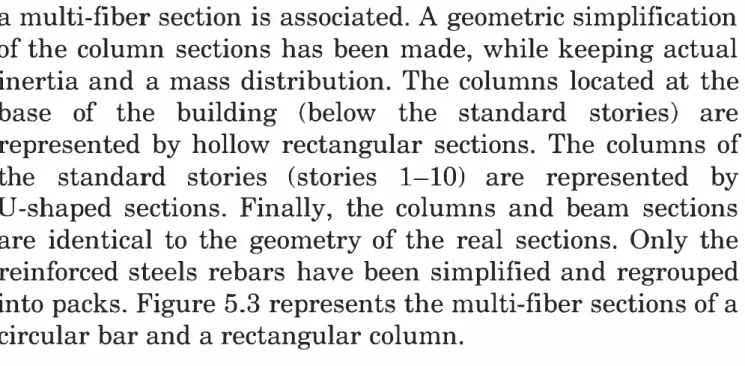
a multi-fiber section is associated. A geometric simplification of the column sections has been made, while keeping actual inertia and a mass distribution. The columns located at the base of the building (below the standard stories) are represented by hollow rectangular sections. The columns of the standard stories (stories 1-10) are represented by U-shaped sections. Finally, the columns and beam sections are identical to the geometry of the real sections. Only the reinforced steels rebars have been simplified and regrouped into packs. Figure 5.3 represents the multi-fiber sections of a circular bar and a rectangular column.
Figure 5.3. Tower - multi-fiber sections of a circular ( ¢45 em) and rectangular beam ( 40 x 50 em) in standard stories, above the load transfer slab. The disposition of concrete fibers is triangular; the steel
reinforcements are represented by square fibers
The prestressed concrete caisson is represented by four longitudinal and three transversal beams, their behavior is considered to be elastic. This assumption aims at taking into account the effect of the prestress, supposed to strongly limit the nonlinearities such as cracking and damage in concrete. Because of the important proportion of thin walls constituting the last story of the structure, this last level is modeled using plastic shell elements. This same kind of element is used to represent all the slabs. The imposed loads added to the weight of the structure are integrated in the definition of the slabs. The final mesh regroups 18,808 elements (including 4,658 multi-fiber beams), 9,808 nodes and 58,848 degrees of freedom (Figure 5.4).
Figure 5.4. Tower - finite element mesh
5.2.3. Constitutive laws
The concrete is represented with a unilateral damage model [LAB 91] defined with two scalar damage variables, one for traction (D1) and one for compression (D2). This representation allows us to take into account opening and closing of cracks (loss and recovery of stiffness) under cyclic loading (Figure 5.5). The behavior of steel is represented by the Menegotto-Pinto elasto-plastic model [MEN 73] with modified kinematic hardening, to take into account the possible buckling of rebars (Figure 5.6).
5.2.4. Validation of the numerical model
A permanent instrumentation of the tower enables the analysis of its behavior with regard to ambient noises [MIC 10]. The vibration measurement with ambient noises allows us to especially evaluate the fundamental frequencies and modal shapes in the real structure (Figure 5. 7). The numerical model of the tower gives a good correlation with the first fundamental frequencies and modal shapes
provided by the in situ tests. The higher modes cannot be determined with accuracy by this experimental analysis. The first two modes correspond, respectively, to a lon
gi
tudinal and transversal global bending. The third mode corresponds to a global torque of the structure. A second longi
tudinal bending mode is characterized by the fourth modal shape. Finally, the fifth mode corresponds to a combined expression of transversal bending and torque.Anelasbcs strams
rr/
Cracking
r Sbft'ness deaease •(
1n LeOSion ---����--£ Sbft'ness decrease In oompr8SS1on �--=-...,.. 'crack dosure Damage llltliallon 111 cxwnpresSIOnFigure 5.5. Tower - La Borderie
constitutive law for concrete. Stress strain realshionship In situ Model 1.16 Hz 110Hz ,"!:-""""""• I ! I 1 1.22 Hz 118Hz (J "
Figure 5.6. Tower - Menegotto Pinto constitutive law for steel.
Stress-strain relationship
145Hz 4.5Hz 5.8Hz
143Hz 4.7Hz 56Hz
Figure 5. 7. Tower -comparison of natural frequencies and modal shapes
between the numerical model and the in situ tests [MIC 10]. For a color version of this figure, see www.iste.co.uk.gueguen/ seismic.zip
The in situ instrumentation of the tower also allows us to record signals from the seismic activity in an Alpine area. The accelerations at the level of the soil (close to the tower) and at six different points of the structure lets us to know the part of the signal transmitted at the base of the structure. These signals allow us to show that the soil structure interaction (for small stress) has a very little influence. This result lets us validate the assumption of a quasi-embedded structure.
The largest signal measured in the tower during the in situ test phase corresponds to the V allorcine earthquake that occurred on September 8, 2005. The behavior of the numerical model subjected to this tri-directional signal is then compared to the experimental results [MIC 10].
Displacement {m)
Displacement
(m)
Displacement at the top: Vallorcine earthquake
Numerical model •1o 10 20 30 40 so ro 10 so �
r
o.,__-�!AW,',\'.' ·l -Measures m.situ Numerical model -2o 10 20 J:Q- 40 50 60 70 80 Ttme (s) X direction Y directionFigure 5.8. Tower - Vallorcine earthquake - top displacement - in situ tests us. numerical model [MIC 10]. For a color version of this figure, see
www. iste. co. uk.gueguen I seismic.zip
The analysis of the top displacements (Figure 5.8) shows a good frequency correlation (>95%) between the in situ tests and the numerical model. Despite the accuracy of the results in terms of the maximum amplitudes of the signals, the
evolution with time of the top displacements presents disparities between the model and the experiments. But as the amplitude of the Vallorcine signal, and consequently the movement of the structure, is extremely low (which is around the millimeter at the top of the structure (52 m)), the coherence of the maximum amplitudes can be considered as being satisfactory.
The maximum values of drift at different stories (Figure 5.9) and the maximum top displacement in the case of the numerical analysis are in agreement with the in situ
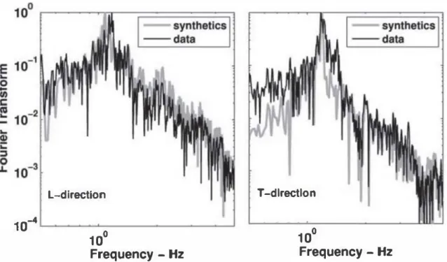
measurements. The top displacement time history also allows us to determine the fundamental frequency contents of the structure by a fast Fourier transform (FFT) (Figure 5.10). Here again, the frequency content provided by the numerical model is in agreement with the frequency provided by the in situ tests. The most important frequencies are clearly identified as the first fundamental modes of the
structure (Figure 5. 7). 40 35 E I 30 ... .c .� 25 � .c g' 20 1J ·:; 15 al 10 5 .,. ... ... ... , , ' ' , ,-' ' ,. ,� � ' ' , .,. , , , , , .,. -10 L-direction ---1DT-direction Model T -direction Model L -direction o��----�---�---� 0 2 4 6 Inter-story drift- m/m x 10-s
Figure 5.9. Tower - Vallorcine earthquake - maximum drift. In situ measurements us. numerical model [MIC 10]
L-dlrectlon 10-4 L..----a.---1 10° Frequency -Hz T -direction 10° Frequency -Hz
Figure 5.1 0. Tower - Vallorcine earthquake - frequency contents (FFT I top displacements). In situ measurements (data) us. numerical model
(synthetics) [MIC 10]
5.2.5. Assessment of the seismic vulnerability (dynamic
simulations)
5.2.5.1. Choice of the dynamic loading
The earthquake signal has been chosen to match with the elastic response spectrum provided by the European standard Eurocode 8 (EC8), including the values of the national part of the Eurocode concerning the seismic zone (established in spring 2009). The elastic response spectrum of the signal is mostly dependent on: the geographical location of the structure (territorial zoning of seismic hazard), the classification of the soil (rock, clay, etc.) and also the importance of the building (housing, administration, etc.). A synthetic three-directional signal, respecting theses specifications of Eurocode 8, has then been artificially generated by ISTerre laboratory [CAU 08]. Also, each of the three components has been established by taking into account characteristics (intensity, frequency, directivity, etc.) of the seismic sources in the Grenoble area. The generation derives from the Green Empirical Functions. Small recordings (e.g. Vallorcine earthquake) associated to a
known source are considered as the Green function of a higher level earthquake for which the signal is determined by simulating a more realistic slip on the studied fault [CAU 08]. Several signals can then be made to match the characteristics of the Belledonne fault in the Grenoble area
[THO 03].
5.2.5.2. Global behavior of the structure submitted to a signal with an ECB elastic response spectrum
The amplitude of the horizontal displacement in the numerical model of the tower, submitted to the signal having the same elastic response spectrum as provided in "EC8" standards, reaches 13.3 and 12.7 em, respectively, for the N-S
(X)
and E-0 (Y) directions (Figures 5. 11 and 5.12).S-EC8 : Displacement at top
��-0---,-i r---,X I
0 20 40 60 80 100
Time (s)
Figure 5.11. Tower- ECB
Earthquake numerical analysis -top displacements in the N-S (X)
direction according to time
S-EC8: Oisplaccrnent at top Dlr iJ
-0.1
�
0 20 40 60 80 100
Time (s)
Figure 5.12. Tower- ECB
Earthquake - numerical analysis top displacements in the E-W (Y)
direction according to time
The stiffness is slightly higher in the lower part of the tower, below the load transfer slab, where the geometry of the columns is rectangular (Figure 5. 13) and also along the story at the top of the tower. The structure is mostly deformed according to the shape of the two first bending modes (Figures 5. 13 and 5. 14), with predominance in amplitude of its fundamental mode. The place where maximum curvature occurs in the second modal shape is located above the transfer caisson.
S-EeS : Deformed shape Umax, column I Em..-,----.,---, Et10 Et9 Et8 Et7 Et6
Storiese•s
Et4 Et3 Et2 Etl Rdc2 Rdc1 -Plle1 dlrX 1 Ss Pile1 dir V ��----��====� .0.15 .0.1 .0.05 0 0.05 0.1 0.15 l.lx(m)Figure 5.13. Tower - ECB
earthquake - numerical analysis maximum deformed shape
-X and Y direction
S-EC8 : Superior defonned shapes, column I (x)
Et11 Et10 E19t Et8� Et7 E16
�
Stories
ets Et4 EIJ Et2t
Et1 Rdc2 Relet Ss .0.01 Ux(m)Figure 5.14. Tower-EC8 earthquake
-numerical analysis -Example of superior bending modes at different
times -X direction
The structure moves as a whole. Indeed, the movement of all the columns is (almost) identical (Figure 5.15). The maximum relative displacement value is about 8 mm and represents less than 7% of the total displacement in the corresponding direction. The displacement of the structure is also characterized by the lack of significant torsion despite the 3D stress and the slight offset of the mass due to the non-symmetrical aspect of the columns.
20
15
Time 10 (s)5
0.�
S-EC8 : relative displacements
Column PI
- Column P4 - Cemer
Uy (m) Ux (m)
Figure 5.15. Tower - ECB earthquake - numerical analysis - displacement in the plane (X, Y) according to time - comparison between three distinct
points of the structure. For a color version of this figure, see
Etll
EtlO
Et9 · ·
Et8 Et7
S tones . Et6 Ets
Et4 Et3 Et2 Etl Rdc2 Rdcl Ss 0 �� !' 1
HDV S-EC8 : Drift max
2 3 Drift • ! .. : .I
Figure 5.16. Tower - ECB earthquake - numerical analysi.s maximum drift by story
The inter-story drift (usually used as indicator of damage), presents a typical value provided by structures submitted to global bending with little shearing. The drift is higher for upper stories (Figure
5.16).
It must be noted that the maximum drift of the upper story remains low due to the high stiffness brought by the walls that compose it. The drift essentially increases above the transfer caisson.It is important to consider that the drift is an indicator characterizing the global damage in a structure (Hazus methodology), and not the local damage in a precise place or area. Indeed, in the case of a structure behaving like a beam in flexion, the inter-story drift can be important at the top of the structure, whereas the maximum stresses (shear forces and bending moments) are higher at the base. This effect can be explained using the curvature of the structure, which can be approached by the derivative of the drift (instead of the drift itself); using the latter, the damaged zones are better characterized.
Looking at the results, two zones present a particular risk: the first concerns the base of the structure where the
shear force and bending moment are the highest due to the first bending mode. The second occurs due to the change in the geometry inducing a high variation in stiffness above the transfer caisson (second bending mode).
5.2.5.3. Local behavior of the structure submitted to a signal with an ECB elastic response spectrum
Though the presence of cracks in concrete due to traction does not lead to structural problems, the study of the damaged areas under traction (D1 > 0. 9) allows for
identifying the zones where rebars could behave in the plastic domain. Damage in traction also leads to energy dissipation, which can influence the non linear behavior of the structure.
A pattern showing the level of damage allows visualizing the zones corresponding to a strong localization of the strains (for high values of D1 and D2 in Figure 5. 17). These zones are concentrated at the base of the columns at the underground level, and along with the first three standard stories above the transfer caisson. Then, damage in traction is also found at the column-beam intersection nodes. The evolution of this variable with time indicates that most of the damage occurs during the first 10 s of the earthquake (out of 100).
Beyond the (local) loss of load bearing capacity, the major risk of damage in compression (D2) is linked to a significant decrease in concrete mechanical properties (approximately
D2 > 0.6), or even its spalling (approximately D2 > 0.9).
Significant spalling combined with high compressive stresses can lead to buckling of the reinforced rebars. However, this risk is not observed in the tower as the damage in compression only reaches a very low maximum value of
Dl 1.00 0.750 0.500 0.250 0.000
Figure 5.17. Tower ECB
earthquake damage due to
traction. For a color version of this figure, see www.iste.co.uk.gueguenl
. . . setsmw.zzp -02 0.250 0 188 0.126 0.062 0.000
Figure 5.18. Tower - ECB
earthquake - damage due to compression. For a color version of this figure, see www. iste.co. uk. gueguen I seismic.zip
The plasticity in the reinforced rebars does not necessarily imply the failure of the structure, but can lead to an end of its use. Indeed with the loss of ductility, steel becomes more fragile and brings uncertainties regarding its behavior. The safety margin is linked to the ductile nature of the steel: when it is consumed, the failure in steel is reached, without any precursor signs. In the situation of an aftershock following the first phase of seismic motion, the situation can be problematic and influences the decisions relative to the future use of the structure (reinforcement, demolition, etc.). Also, the cyclic loading makes steel reinforcement more prone to fatigue, and so to premature failure. Moreover, the residual strains due to plasticity lead to permanent cracks in concrete. This situation can deteriorate concrete durability and thus increase the risk of corrosion of the reinforcement which can require reparation and protection intervention. Monitoring the evolution of strains in the reinforced rebars can help for an evaluation of these problems.
The tower has two zones where residual plastic displacement in steel is observed. The first is at the base of the structure, at the bottom of the rectangular columns (Figure 5.19). The plastic permanent strains remain relatively low, but are located in a critical area. Much more residual displacement is observed in the second zone with a strain value of 5.2 x 10⁻³ at the bottom of the standard
stories, in the part above the transfer caisson. The whole first underground level and the two first standard stories
therefore present important structural disorders.
EIIO Et9 E18 E17 Et6
Stories
ets E14 Et3r E12f E11 Rdc2L Rdc1l
Ss(a)
S-EC8 : Strains in steel �--Column C I
t- Pla.<tilic:nion
4
S-EC8 : Strains in steel
E110 E19 E18 Et7 E16
Stories
e•sr E14(b)
Et3 Et2 E11 Rdc2� Rdc1[
Ss -2 -1 0 -Colum11C� M Pla<ll ficaoon 2 3 4 5 e x to·'Figure 5.19. Tower - ECB earthquake - numerical analysis. Envelope of
the strains in reinforced rebars (a) column 1 and (b) column 4 (yield plastic strain = 0.2%)
5.2.5.4. Estimation of the damage level
The main conclusions of the previous analysis are summarized as follows:
1) Important cracks in concrete can be observed at the underground level on the first four standard stories above the transfer caisson.
2) Significant residual displacement due to plasticity is observed in reinforced rebars of the columns at the two first standard stories and in smaller values at the level of the underground columns. The maximum strains (ffi5.2 x 10-3)
still remain very low compared to the failure limit in traction (9 x 10⁻²).
3) No rupture by compression in concrete or buckling in reinforced rebars is observed. Several reinforced rebars experienced plasticity. However the global bearing capacity of the structure is not decreased.
4) The European Macro-seismic Scale EMS-98 [EMS 01] and RISK-UE (LMl) [RIS 03] offer a structural definition (cracking, spalling of concrete, etc.) of the damage levels (Figure 5.20). The numerical evaluation of these levels according to the local damage indicators is based on the method proposed by [LAN 02].
In the case of the HAZUS [HAZ 03] and RISK-UE (LM2) [RIS 03] methods, the qualification of these levels depends on global criteria (drift and top displacements) (Figure 5.21), this scale being more adapted to the classical methods of global analysis or the measurements made by in situ experiments.
- For the tower, the correspondence with the EMS-98 classification allows qualifying the damage level as moderate (level 2/5).
- From the point of view of the HAZUS method, the maximum drift of 4.8 x 10⁻³ obtained during the dynamic
analysis corresponds to a moderate damage level (level 2/4), which is in agreement with the damage level previously defined by the EMS-98 recommendation.
- Considering the RISK-UE (LM2) recommendations, the maximum top displacements reached correspond to a very high damage level (level 4/5). The damage is slightly overevaluated by this indicator. It should be noted that the calculation of this indicator requires the knowledge of the displacement at the yield limit and at the failure limit of the structure (in accordance with RISK-UE), which is easily available with a pushover analysis.
Level of damage EMS-98 and RISK-UE (LM1) 1: None to low :Very high Structural defmition EMS-98
Superficial cracking, non structural damage.
Cracking through al elements, fall friable materials and
mortar. Cracking of structural elements, spalling of concrete, buckling of longitudinal reinforced rebars. Concrete fail by compression, failure of
reinforced rebars and
lllllllllllll
l
steel-concrete adherence lost.-;o,�=-•r...o. Some columns or upper
story collapse.
ery important structural 1 ... ,�u''-'-F>'v· destruction of
bottom floor and part of the structure. Identification criteria (Numerical analysis) Maximum value (DI=l) of damage by traction is reached in given zones.
Non linearities are developed into structure, with stiffness decreasing. Wall begins to enter the plastic domain.
N onlineari ties increase and stiffness
decreases. All the reinforced rebars in
the walls of a same story enter in the
plastic domain.
Concrete failure by compression (D2= 1) or
reinforced rebars fail on the peripheral
fibers.
Concrete failure by compression (D2 = 1)
or reinforced rebars fail over all the fibers
of a wall. Resting shear force capacity a
the base of the wall reduced around 66%.
Figure 5.20. EMS-98-definition of the damage scale and criteria used in the numerical analysis
Level of damage HAZUS-Drift RISK-UE (LM2) Displacement at tog
Light 0.0015 0.1Dy < fl< 0.7fly + O.OS�y
Moderate 0.003 0.7/ly + 0.05/luy< ll< 0.7/ly + 0.21luy Strong 0.008 0.7/ly + 0.21luy< ll< 0.7/ly + O.Siluy Collapse 0.02 0.7fly + O.Sflyy< fl< 0.7fly + fluy
(C2 building, great height) With L'l11y= 0.9!111- 0.7lly U=ultimatc (collapse); y=yield (plastification)
Figure 5.21. Definition of the HAZUS and RISK-UE (LM2)
damage levels
5.2.6. Estimation of the seismic vulnerability using
pushover analysis
5.2.6.1. Choice of the static loading
The nonlinear static analysis by pushover consists of studying the behavior of a structure subjected to an increasing unidirectional static lateral loading. The evolutions of the top displacements and of the total resisting shear force are then used to estimate the behavior of the structure. The lateral loading is defined here according to Eurocode 8 supposing that the first bending mode is predominant. The loading force is applied at each story (as a force distributed on the slab) with a value linked to the mass and to the height of a considered story. The loading profile obtained for the tower is represented in Figure 5.22. The mass of the transfer caisson being high, a large value of force above the main entrance hall has to be considered. The evolution of the loading is applied until the failure of the structure, here characterized by the rupture of reinforced rebars. The stress applied on the 3D model allows us to detect possible phenomena of torsion.
The choice of the loading adopted for the pushover analysis is strongly conditioned by the dynamic behavior of the structure. The applied loading has to be representative of the natural modes taking part in at least at 90% of the total mass of the structure. In the case of the tower, the modal participation of the mass is limited to 55% for the first
bending mode. It would then be convenient to turn toward a multimodal pushover [CHO 01, CHO 04] and take the three first bending modes into account to reach the 90% of the participating mass. Also, when several modes are used for a pushover analysis, as their influence is not the same at the same time [MWA 00], an adaptive multimodal pushover [ANT 04, KAL 06] is the most appropriate. However, either multimodal pushover or adaptive multimodal pushover, remains heavy in terms of computational costs. These kinds of analysis are not currently often used by practitioners and do not allow us access to indicators such as the "performance point". The choice has been made to only consider the first mode for defining the pushover analysis in order to stay among conventional tools orientated toward engineering. The results presented hereafter are to be considered considering the above remarks and not as a perfect quantitative comparison between the dynamic analysis and the static pushover analysis.
--+
__.�����-+����
_.�����-+����
F.
1
=
1
17-1
b, x
---(Zi mi)
L,(m1 Z)
Fi: Force by story i Zi and Zj: level of two consecutive stories i and j (as
off the ground)
mi and mj: mass of two consecutive stories i and j
Fb: total effort at the base
Figure 5.22. Tower - pushover analysis - distribution of the
loading over the height of the structure
5.2.6.2. Global behavior of the structure, static analysis
The global behavior of the structure has two different phases in the two horizon tal directions (Figure 5. 23). The first phase is characterized by an elastic behavior of the structure, and the second phase by a global hardening of the force displacement curve. The fragile behavior observed from the force-displacement curves essentially comes from the fact that the test is piloted in force and not in displacement. In its elastic part, the ductility in the longitudinal direction N-S
(X)
is twice the ductility found in the transversal direction E-W (Y). However, the damage is reached for similar values of lateral force in both the directions. The dissymmetry of the columns in theX
and Y directions relative to their U shape explains this phenomenon. The ultimate point of the pushover curves corresponds to a local collapse, caused by failure of a significant number of reinforced bars, either in traction(X
direction), and either in compression by buckling (Y direction).P-ECII-X P-ECII-Y 16000 16000 14000 14000 12000 12000 � 10000 g � 10000 g 8 8000 16000 -dlrY(E.O)
a)
0 IL 8000l- IL 6000-4000 4000 2000 2000 00 0.05 0.1 015 0.2 0.25 0.3 0.35 00 0.05 0.1 0.15 0.2 025 0.3 Ulc(m) Uy(m) b)Figure 5.23. Tower- pushover analysis-shear force at base us.
displacement at top (a) X directions (N-S) and (b) Y directions (E-W)
5.2.6.3. Local behavior of the structure, static analysis
0.35
For the two directions of loading, failure occurs at the columns. According to the
X
(N-8) loading, the rupture of the reinforced rebars is reached in traction (Figure 5.24) for astrain of 9%, with significant damage localization at the bottom of the standard stories. According to the Y loading, the failure in the reinforced rebars intervenes by buckling, with a compression strain in the concrete higher than 3.5 x
10-3, leading to spalling (Figure 5.24). In this direction, strain localization is less important.
S-EC8 : Deformation of steel S-EC8 : Defonnation of steel
E110�--rr:-:---;
===::==�
Et9 -Column P1
Eta: CoUmP4
Et7 PlaSiiflcation
S
tones
. E161 Ets Et4 Etl Et2: Ell Rdc2: Rdcl .0.02 0 0.02 0.0.. 0.06 0.08 0.1 F. Euo� E19 E18 E17Stories�::
E14 Et3 Et2 Ell Rdc2 Rdo1 Ss 1 --0 s & -ColuiTTl P1 Coi111TV1 P4 Plasttlicatlon 10 15 � 10..,Figure 5.24. Tower pushover analysis strains in the reinforced rebars -envelope curve - loading directions X and Y For a color version of this
figure, see www. iste.co. uk.gueguen I seismic.zip
5.2.6.4. Damage level estimation
The results of the pushover analysis can be used for defining the performance point of the structure. Looking for the performance point aims at predicting from the nonlinear static analysis the conditions (force at the base and displacement at the top) that will be experienced by the structure during a given dynamic stress. Also, the performance point is used to determine the state of damage of the structure and its value compared to the different damage levels provided by the recommendations (see section 5.2.5.4).
5.2.6.4.1. RISK-UE (LM2) [RIS 03] method
In the case of the RISK-DE (LM2) methods, the damage levels are conditioned by the value of the top displacement according to the ultimate displacement (Figure 5.21). With this approach, the damage level corresponding to the target
displacement is high (I) (level 2/4) in the
X
direction and very high (TI) (level 3/4) in theY direction (Figure 5.25).P-EC8-X : Perfonnancc point
t
-
•�
Sd�0.07356m=2.62
• Dama� RISK-UE
0.05 0.1 0.15 0.2
Sd(m)
P-EC8-Y : Pcrfonnonce point
[-,·=3.09
• Sd:o0.060799m• Dama� RISK.UE
0.05 0.1 0.15 0.2 0.25
Sd(m)
Figure 5.25. Tower - performance point and classification of the damage
levels with the RISK-UE (LM2) method. For a color version of this figure, see www. iste.co. uk.gueguen I seismic.zip
The comparison of the damage level with a structural indicator to provided by EMS-98 (or RISK-UE (LMl)) is described hereafter. This compression will prove the accuracy of this damage level.
5.2.6.4.2. EM-98 [EMS 01] method
The EMS-98 method allows us to define the damage level based on structural observations; its definition can be associated with the damage indicators coming from the numerical analysis (cracking in concrete, plasticity in the reinforced rebars, etc.) [LAN 02] (Figure 5.20). The interpretation of the EMS-98 method corresponding to the target displacement is estimated to be moderate structural damage (M) (level 3/5) in the
X
direction and high (H) (level 4/5) in theY direction (Figure 5.26).A good coherence between the RISK-UE (LM2) and EMS-98 methods is observed. Each of them presents the structure as being at half way of the penultimate class of damage in the
X
direction and at the beginning of the last class in theY direction.7
P-EC8-X : Performance point
---r
-0.05 0.1 0.15 0.2
Sd (m)
0.25 0.05 0.1 0.15 0.2 0.25 Sd (m)
Figure 5.26. Tower - performance point and classification of the damage
levels according to the EM-98 scale. For a color version of this figure, see
www. iste.co. uk.gueguen I seismic.zip
5.2.6.4.3. Exploitation and interpretation regarding the dynamic analysis
Regarding the EMS-98 classification, the damage level from the dynamic analysis can be qualified as moderate (level 2/5). From the point of view of static analysis, the performance point indicates that the structure is in a very high state of damage in agreement with RISK-UE and moderate looking at the EMS-98 classification. However, the position of the performance point is close to the limit between levels 2 and 3.
The spectral displacement corresponding to the performance point allows us to define the maximum displacement expected at the top of the structure through the behavior coefficient. The displacements at the top in the static and dynamic cases are coherent in the
X
direction (with a difference lower than 10%) but not in theY direction (Figure 5.27). In the opposite of the dynamic analysis, the absence of cycle loading in the pushover analysis leads to a more pronounced localization of damage. An important difference (100%) is observed for the shear forces at the base between the two analyses. The participation of highernatural modes during the dynamic analysis could explain this difference.
9
3
2
P-EC&-X : performance point
i -11::2.62 I
--.
r:=
--
�
---
"'"
� Sd::0.07356m 1I
0.05 Ma.ximum displacement at the top in dynamicaJ situation 0.1 0.15 Sd (m) 02 0.25 9 7 6 I �5 \ � \ ';'4 II) 3 2P-EC&-Y : performance point J.1=3.09
j • Sd=0.060799m
0.05
Maximum
displacement at the
top in d) narn ical situation
0.1 0 15 0.2
Sd(m) 0.25
Figure 5.27. Tower - performance point and maximum displacement under dynamic loading. For a color version of this figure, see
www. iste. co. uk.gueguen I seismic. zip
5.3. Conclusions
This chapter presents different modeling strategies for the eva]uation of the seismic vulnerability of existing structures by focusing on simplified methods and more specifically on the use of multi-fiber beam elements. A vulnerability analysis applied to an existing structure is then provided. The keypoints of the study are the following:
- The dynamic behavior of the structure shows two structural sensitive zones: at the base, and at the bottom of the standard stories. The degradations remain moderate, as plasticity in reinforced rebars of certain zones appears but remains limited to low values. A participation of the second and third bending mode is shown, especially when damage of the U-shaped columns at the base of the standard stories occurs. The comparison between the pushover (based on the first bending mode) and the dynamic analysis shows very close maximal deformed shapes of the structure.
- The use of the same damage indicators as those used for the dynamic analysis enables a comparison of their accuracy.
In addition, the analysis on the multi-fiber model enables us to exploit the EMS-98 damage levels for which its description is related to local variables.
- The multi-fiber beam strategy allows us to fully exploit the definitions of the damage level based on structural criteria. This is a considerable advantage compared to the classic evaluations based on the drift or the top displacement. In addition, this classification does not require an analysis leading to the total failure of the structure as in the pushover analysis. A dynamic analysis then allows us to directly quantify the level of structural damage. This point is important as the computational cost needed in the pushover analysis is often higher here than for a dynamic analysis.
The structure having an irregular geometry leads to the fact that a participation of the higher modes in the dynamic behavior has to be considered (as shown by the dynamic analysis). A mu[timodal pushover [CHO 04] or multimodal adaptive pushover [ANT 04, KAL 06] could increase the reliability of the results (for a larger computational cost) while conserving the analysis methodology.
A new study of the vulnerability of the structure, this time reinforced (numerically) by using carbon fiber tissues, is presented in [DES 09], [DES 10], [DES 11] and [DES 13].
The previous study carried out has a deterministic character, in the sense that we are interested in the behavior of a perfectly defined structure under a well known imposed stress. One of the perspectives could be to adopt a probabilistic approach, in order to estimate the seismic signals harmfulness and the properties of the structure.
5.4. Caution
The work presented here uses the city hall tower as the base of a case study and is in no manner representative of a requirement or an official demand issued from a risk linked to the stability of the structure.
5.5. Acknowledgments
This work has been carried out as part of the ANR ARVISE, project ANR-2006-PGCU-007-01.
5.6. Bibliography
[ABS 72] ABSI E., "La theorie des equivalences et son application a l'etude des ouvrages d'art", Annales de I.T.B.T.P., no. 295, October 1972.
[ANT 04] ANTONIOU S., PINHO R., "Advantages and limitations of
adaptive and non-adaptive force-based pushover procedures",
Journal of Earthquake Engineering, vol. 8, no. 4, pp. 497-522,
2004.
[ARV] ANR ARVISE, "Analyse et Reduction de la Vulnerabilite Sismique du bati Existant", available at: http://arvise. grenoble inp. fr.
[CAl 13] CAILLERIE D., KOTRONIS P., CYBULSKI R., "An improved
Timoshenko finite element beam with internal degrees of
freedom", Computers and Structures in Production.
[CAU 08] CAUSSE M., COTTON F., CORNOU C., BARD P.Y., "Calibrating median and uncertainty estimates for a practical
use of empirical Green's functions technique", Bulletin of the
Seismological Society of America, vol. 98, no. 1, pp. 344-353,
2008.
[CER 07] CERESA P., PETRINI L., PINHO R., "Flexure-shear fiber beam-column elements for modeling frame structures under seismic loading - state of the art", Journal of Earthquake
[CHA 09] CHATZIGOGOS C.T., PECKER A., SALENQON J., "Macroelement modeling of shallow foundations", Soil
Dynamics and Earthquake Engineering, vol. 29, no. 5,
pp. 765-781, 2009.
[CHA 11] CHATZIGOGOS C.T., FIGINI R., PECKER A., SALEN<;ON J., "A macroelement formulation for shallow foundations on cohesive
and frictional soils", International Journal for Numerical and
Analytical Methods in Geomechanics, vol. 35, no. 8, pp. 902-931,
2011.
[CHO 01] CHOPRA A.K., GOEL R.K., A modal pushover analysis procedure to estimate seismic demands for buildings : theory and preliminary evaluation, PEER Report, Pacific Earthquake Engineering Research Center, 2001.
[CHO 04] CHOPRA A.K., GOEL R.K., "A modal pushover analysis procedure to estimate seismic demands for unsymmetric-plan
buildings", Earthquake Engineering and Structural Dynamics,
vol. 33, pp. 903-927, 2004.
[COL 78] COLLINS M.P., "Toward a rational theory for RC members in shear", Journal of the Structural Division, vol. 104, no. 4, pp. 649-666, 1978.
[COM 00] COMBESCURE D., PEGON P., "Application of the local-to global approach to the study of infilled frame structures under seismic loading", Nuclear Engineering and Design, vol. 196, pp. 17-40, 2000.
[COM 0 1] COMBESCURE D., Modelisation des structures de genie
civil sous chargement sismique a l'aide de eastern 2000, Report
DM2S SEMT/EMSI/RT/01-008/A, CEA Saclay, 2001, available at http://www-cast3m.cea.fr.
[CRE 01] CREMER C., PECKER A., DAVENNE L., "Cyclic macro element for soil-structure interaction: material and geometrical
non-linearities", International Journal for Numerical and
Analytical Methods in Geomechanics, vol. 25, no. 13,
pp. 1257-1284, 2001.
[CRE 02] CREMER C., PECKER A., DAVENNE L., "Modelling of nonlinear dynamic behaviour of a shallow strip foundation with macro element", Journal of Earthquake Engineering, vol. 6, no. 2, pp. 175-211, 2002.
[DAW 89] DAWE J.L., SEAR C .K., "Behavior of masonry infilled steel frames", Canadian Journal of Civil Engineering, vol. 16, pp. 865-76, 1989.
[DES 09] DESPREZ C., KOTRONIS P., MAZARS J., PAULTRE P., ROY N., TROUDEAU M., "Retrofitting reinforced concrete structures with FRP: numerical simulations using multifiber beam elements",
Proceedings of the 2nd International Conference on Computational Methods in Structural Dynamics and Earthquake Engineering (COMPDYN 2009), Paper no. 389,
Island of Rhodes, Greece, 22-24 June, 2009.
[DES 10] DESPREZ C., Analyse et reduction de la vulnerabilite sismique des structures existantes: renforcement par collage de tis sus de fibres de carbone (TFC), PhD Thesis, Institut National Polytechnique de Grenoble - Grenoble Universities, 2010, available at http:l/tel.archives-ouvertes.fr/tel-00560438/fr.
[DES 1 1] DESPREZ C., KOTRONIS P., MAZARS J., "Analyse et Reduction de la Vulnerabilite Sismique d'une Structure Existante en Beton Arme: renforcement par TFC", Actes du Beme
Colloque National de l 'Association Franr;aise de Genie
Parasismique AFPS 201 1, CD paper 96, Ecole des Pants
ParisTech, Marne-La-Vallee, pp. 383-389, 12-14 September 2011.
[DES 12] DESPREZ C., MAZARS J., KOTRONIS P., PAULTRE P., Damage model for FRP-confined concrete columns under cyclic loading, Engineering Structures, vol. 48, pp. 519-531, March 2013.
[DUR 94] DURRANI A.J., Luo Y.H., "Seismic retrofit of flat slab buildings with masonry infill", Proceedings of the NCEER Workshop on Seismic Response of Masonry Infills, San Francisco, CA, 1994.
[ELD 03] ELDAKHAKHNI W., ELGAALY M., HAMID A., "Three-Strut model for concrete masonry-infilled steel frames", Journal of Structural Engineering, vol. 129, no. 2, pp. 177-185, 2003.
[ELO 91] ELOUALI T., HOUDE J., TINAWI R., "Comportement d'un
cadre rempli soumis a un chargement cyclique: modelisation
pour une analyse dynamique non lineaire", Canadian Journal
[EMS 0 1] EMS-98, "L'Echelle Macrosismique Europeenne 1998.
Conseil de !'Europe", Cahiers du centre europeen de
geodynamique et de seismologie, vol. 19, pp. 14-20, 2001.
[FAR 91] FARDIS M., "Member-type models for the non linear seismic response analysis of reinforced concrete structures",
Experimental and Numerical Methods in Earthquake
Engineering, E URO Courses, Reliability and Risk Analysis,
vol. 2, JRC Ispra, Italy, 1991.
[GOT 99] GOTTARDI G., HOULSBY G.T., BUTTERFIELD R., "Plastic response of circular footings under general planar loading",
Geotechnique, vol. 49, no. 4, pp. 453-469, 1999.
[GRA 08a] GRANGE S., Modelisation simplifiee 3D de !'interaction sol-structure: application au genie parasismique, PhD Thesis, Institut National Polytechnique de Grenoble - Grenoble Universities, 2008, available at http://tel.archives ouvertes .fr/tel-00306842/fr.
[GRA 08b] GRANGE S., KOTRONIS P., MAZARS J., "A macro-element for a circular foundation to simulate 3D soil-structure interaction", International Journal for Numerical and
Analytical Methods in Geomechanics, vol. 32, no. 10,
pp. 1205-1227, 2008.
[GRA 08c] GRANGE S., KOTRONIS P., MAZARS J., "A macro-element for a shallow foundation to simulate soil-structure interaction considering uplift", C. R. Mecanique, vol. 336, nos. 1 1-12, pp. 856-862, 2008.
[GRA 09a] GRANGE S., KOTRONIS P., MAZARS J., "A macro-element to simulate 3D soil-structure interaction considering plasticity and uplift", International Journal of Solids and Structures,
vol. 46, no. 20, pp. 3651-3663, 2009.
[GRA 09b] GRANGE S., KOTRONIS P., MAZARS J., "A macro-element to simulate dynamic soil-structure interaction", Engineering Structures, vol. 31, no. 12, pp. 3034-3046, 2009.
[GRA 09c] GRANGE S., KOTRONIS P., MAZARS J., "Numerical modelling of the seismic behaviour of a 7 -story building: NEES
benchmark", Materials and Structures, vol. 42, no. 10,
[GRA 11] GRANGE S., BOTRUGNO L., KOTRONIS P., TAMAGNINI C., "On the influence of soil structure interaction on a reinforced
concrete bridge", Earthquake Engineering and Structural
Dynamics, vol. 40, no. 1, pp. 93-105, 2011.
[GUE 94] GUEDES J., PEGON P., PINTO A�, A fibre timoshenko beam element in eastern 2000, Special publication nr. i.94.31, Technical report, J.R.C ., I-21020, Ispra, Italy, 1994.
[HAZ 03] HAzus, FEMA's Methodology for Estimating Potential Losses from Disasters, 2003, available at http://www .fema.gov/ plan/preventlhazus/index.shtm.
[HRE 41] HRENNIKOFF A., "Solution of problems of elasticity by the frame-work method", ASME Journal of Applied Mechanics,
vol. 8, pp. A619-A7 15, 1941.
[HSU 88] Hsu T.T.C., "Softening truss model theory for shear and torsion", ACI Structural Journal, vol. 85, no. 6, pp. 624-635, 1988.
[ILE 00] ILE N., REYNOUARD J.M., "Nonlinear analysis of reinforced concrete shear wall under earthquake loading", Journal of Earthquake Engineering, vol. 4, no. 2, pp. 183-213, 2000.
[KAL 06] KALKAN E., KUNNATH S.K., "Adaptive modal combination
procedure for nonlinear static analysis of building structures",
Journal of Structural Engineering, vol. 132, No. 11, pp. 1721-1731, 2006.
[KOT 00] KOTRONIS P., Cisaillement dynamique de murs en beton arme. Mod€des simplifies 2D et 3D, PhD Thesis, ENS Cachan, 2000, available at http:/ltel.archives-ouvertes.fr/tel-00074469/fr.
[KOT 03] KOTRONIS P., MAZARS J., DAVENNE L., "The equivalent reinforced concrete model for simulating the behavior of shear
walls under dynamic loading", Engineering Fracture Mechanics,
vol. 70, nos 7-8, pp. 1085-1097, 2003.
[KOT 05a] KOTRONIS P., MAZARS J., "Simplified modelling
strategies to simulate the dynamic behaviour of RC walls",
Journal of Earthquake Engineering, vol. 9, no. 2, pp. 285-306,
[KOT 05b] KOTRONIS P., RAGUENEAU F., MAZARS J., "A simplified modelling strategy for RC walls satisfying PS92 and EC8 design", Engineering Structures, vol. 27, no. 8, pp . 1 197-1208, 2005.
[KOT 08] KOTRONIS P., Strategies de Modelisation de Structures en Beton Soumises a des Chargements Severes, Habilitation a Diriger des Recherches, University Joseph Fourier, 2008, available at http:/ltel.archives-ouvertes.fr/tel-00350461/fr.
[LAB 91] LA BORDERIE C., Phenomenes unilateraux dans un
materiau endommageable: modelisation et application a
l'analyse des structures en beton, PhD Thesis, University of Paris VI, Paris, France, 1991.
[LAN 02] LANG K., Seismic vulnerability of existing building, PhD Thesis, Swiss Federal Institute of Technology, Zurich, 2002.
[MAl 71]1 MAINSTONE R.J., "On the stiffnesses and strengths of infilled frames", Proceedings of the Institution of Civil
Engineers, vol. 73605, pp. 57-90, 1971.
[MAZ 02] MAZARS J., KOTRONIS P., DAVENNE L., "A new modelling strategy for the behaviour of shear walls under dynamic loading", Earthquake Engineering and Structural Dynamics,
vol. 3 1 , no. 4, pp. 937-954, 2002.
[MAZ 04] MAZARS J., RAGUENEAU F., CASAUX G., COLOMBO A., KOTRONIS P., "Numerical modelling for earthquake engineering: the case of lightly RC structural walls", International Journal for Numerical and Analytical Methods in Geomechanics, vol. 28,
no. 7-8, pp. 857-874, 2004.
[MAZ 06] MAZARS J., KOTRONIS P., RAGUENEAU F., CASAUX G., "Using multifiber beams to account for shear and torsion. Applications to concrete structural elements", Computer
Methods in Applied Mechanics and Engineering, vol. 195,
no. 52, pp. 7264-7281, 2006.
[MEN 73] MENEGOTTO J., PINTO P., "Method of analysis of cyclically loaded reinforced concrete plane frames including changes in geometry and non -elastic behaviour of elements
under combined normal force and bending'', IABSE Symposium
on Resistance and Ultimate Deformability of Structures Acted on
[MIC 10] MICHEL C., GUEGUEN P., EL AREM S., MAZARS J., KOTRONIS P., "Full scale dynamic response of a RC building under weak seismic motions using earthquake loadings,
ambient vibrations and modelling", Earthquake Engineering
and Structural Dynamics, vol. 39, no. 4, pp. 419-441, 2010.
[MOR 20] MORSCH E . , Der Eisenbetonbau-Seine Theorie und Anwendung, 5th ed., vol. 1, Part 1, Wittwer, Stuttgart, 1920.
[MWA 00] MWARFY A.M., ELNASHAI A.S., Static Pushover versus
Dynamic Collapse Analysis of RC Buildings, Department of
Civil and Environmental Engineering, Imperial College, London, 2000.
[NOV 91] NOVA R., MONTRASIO L., "Settlements of shallow
foundations on sand", Geotechnique, vol. 41, no. 2, pp. 243-256,
1991.
[PAP 10] PAPACHRISTIDIS A., FRAGIADAKIS M., PAPADRAKAKIS M., "A 3D fibre beam-column element with shear modelling for the inelastic analysis of steel structures", Computational
Mechanics, vol. 45, pp. 553-572, 2010.
[PEG 94] PEGON P., A Timoshenko simple beam element in eastern 2000, Technical report, J.R.C., I-21020, Special publication no. 1.94.04, Ispra, Italy, 1994.
[PET 99] PETRANGELI M., PINTO P., CIAMPI V., "Fiber element for
cyclic bending and shear of rc structutes. i: Theory", Journal of
Engineering Mechanics, vol. 125, no. 9, pp. 994-1001, 1999.
[POL 98] POLITOPOULOS I., Etude bibliographique modelisation des batiments en beton arme, SEMT/EMSIIRT/98-047A, CEA Saclay, 1998.
sur la Report
[RIS 03] RISK-UE Pro
j
ect, An Advanced Approach to Earthquake Risk Scenarios with Applications to Different European Towns.WP04: Vulnerability of Current Buildings Handbook. Inst. of Earthquake Engng. a. Engng. Seismol. (IZIIS), Skopje, Contract No. EVK4-CT-2000-00014, 2003.
[RIT 99] RITTER W., "Die bauweise hennebique", Schweizerische
[SAM 1 1] SAMOUH H., KOTRONIS P., "Modelisation simplifiee des portiques avec remplissage en mac;onnerie soumis a !'action sismique", Actes du Beme Colloque National de [ 'Association
Franc;aise de Genie Parasismique AFPS 2011 , CD paper 92,
Ecole des Ponts ParisTech, Marne-La-Vallee, pp. 633-641, 12-14 September 2011.
[SPA 96] SPACONE E., FILIPPOU F., TAUCER F., "Fiber beam-column model for nonlinear analysis of rc frames. i: Formulation",
Earthquake Engineering and Structural Dynamics, vol. 25, no. 7, pp. 711-725, 1996.
[STAF 63] STAFFORD SMITH B., "Lateral stiffness of infilled frames", Journal of Structural Division, vol. 88, no. ST 6, pp. 183-199, 1963.
[THO 03] THOUVENOT F., FRECHET J., JENATTON L., GAMOND J.F., "The Belledonne Border Fault: identification of an active seismic strike-slip fault in the western Alps", Geophysical Journal International, vol. 155, no. 1, pp. 174-192, 2003.

![Figure 5. 7. Tower - comparison of natural frequencies and modal shapes between the numerical model and the in situ tests [MIC 10]](https://thumb-eu.123doks.com/thumbv2/123doknet/7959490.266671/9.893.121.835.804.1062/figure-tower-comparison-natural-frequencies-modal-shapes-numerical.webp)
![Figure 5.8. Tower - Vallorcine earthquake - top displacement - in situ tests us. numerical model [MIC 10]](https://thumb-eu.123doks.com/thumbv2/123doknet/7959490.266671/10.893.53.781.560.902/figure-tower-vallorcine-earthquake-displacement-tests-numerical-model.webp)