COEVOLUTIVE META-EXECUTION SUPPORT
Towards a design and execution continuum
Gilles Dodinet*
,**, Michel Zam*
,**, Geneviève Jomier*
*LAMSADE, Univ. Paris-Dauphine, Paris, France Place du Maréchal de Lattre de Tassigny 75775 Paris **KARMICSOFT, 25 avenue de la République, 92500 Bourg La Reine
[email protected], [email protected], [email protected]
Keywords: Software evolution, collaborative development, model-driven engineering.
Abstract: Despite its promises, the lack of support for consistent coevolution of models with theirs meta-models and instances prevents a broader adoption of MDE. This article presents a coevolution support for reflective meta-models and their instances tightly integrated into an execution platform. The platform allows stakeholders, developers and final users to define, update and run models and theirs instances concurrently. Design changes are reflected immediately in the running applications, hosted by the platform. Both instances and models are stored in a shared multi-version database that brings persistency, consistency and traceability support. A web-based implementation of the platform validates the approach and sets the foundations for a collaborative integrated development environment that evolves continuously.
1. INTRODUCTION
Model Driven Engineering (MDE) considers models as first-class citizens in the development process. However, consistent evolution, and thus coevolution, of target systems, their models and their meta-models is both a necessity and a challenge.
The last decade has seen a rapid expansion of MDE techniques and applications, partly due to hopes of knowledge capitalization. While software development process is a “multilevel, multiloop feedback system” involving a variety of actors (Lehman, 1998), the main responsibility still relays on the developer’s shoulders. Although the stakeholder has the best understanding of the functional requirements, he is still kept away from the whole development process.
In order to reduce the effect of software aging (Grubb and Takang, 2005), and the associated maintenance cost (about 50% to 75% of the global development cost, McKee, 1980), the stakeholder must be actively involved in the software process (Ambler and Jeffries, 2002). As a consequence, in a MDE context, any model evolution should be immediately reflected in the system to assert its validity. To support such requirements, ad hoc tools must be provided to merge the development
and execution phases. (Agrawal et al., 2009) acknowledges the need for tools that would give greater power to stakeholder while empowering the developer.
The coevolution of models with their own models (called meta-models) and with their instances remains a critical issue. (Van Deursen et al., 2007) points the following paradox: while MDE approaches have been designed to handle continuous evolution there’s today little support for model and meta-model coevolution. This paradox also applies to coevolution of models and their instances - i.e. the systems represented by these models. Today models are essentially static artifacts: they usually do not evolve easily after the initial development phase. Once a system is deployed, any modification made to the structure of its model cannot be propagated to the running system without going through another full development cycle.
This article presents a shared execution environment built upon a collaborative modeling support that intends to answer the general problem of coevolution of models and their instances. The system is decomposed into fine-grain elements common to the various abstraction levels. They are used to express both models and their instances, including application data and programs.
The article focuses on data-centered applications using relational database to represent models and meta-models stored as user data and metadata.
The next section describes a typical evolution scenario spanning all abstraction layers; section 3 presents related work; section 4 presents the proposed solution and section 5 describes an implementation. Section 6 concludes and opens perspectives.
2. COEVOLUTION SCENARIO
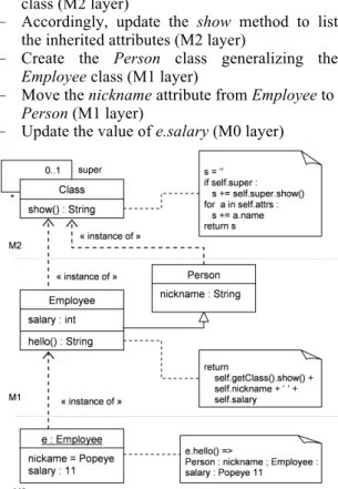
As requirements change, modifications can occur at any abstraction level and must be propagated consistently. The simple, yet representative, scenario below illustrates such coevolution.Figure 1: Employee class, version 1
Figure 1 shows the initial state of the scenario introducing the Employee class and an instance, e.
Employee is also an instance of the Class class and
defines the hello instance method. A call to hello prints the class structure (via a call to the show method defined in the Class class), followed by the attribute values of e. To simplify, the Attribute class does not appear. UML 2.x class diagram notation is used and the pseudo-code is inspired by Python syntax.
M0, M1 and M2 represent abstraction layers as defined by the OMG modeling stack (OMG, 2001). M2 is the meta-model layer. M1 is the model layer. Any model element defined in M1 is an instance of a meta-element defined in M2. M0 is the system layer; every system element in M0 is an instance of a model element defined in M1.
Layers M3 (meta-meta-model level) and M2 are merged.
The goal is to be able to modify all three layers dynamically, while the system is still running, and take the modifications into account immediately without restarting or redeploying the system.
Figure 2 shows the result of important evolutions: the introduction of the single
inheritance concept used by the Employee class,
while its instance is subject to an independent update (salary raise). This is achieved by executing the following operations:
–
Add a reflexive association, super, to the Class class (M2 layer)–
Accordingly, update the show method to list the inherited attributes (M2 layer)–
Create the Person class generalizing theEmployee class (M1 layer)
–
Move the nickname attribute from Employee toPerson (M1 layer)
–
Update the value of e.salary (M0 layer)Figure 2: Employee class, version 2
The result of the execution of e.hello() is shown on the right hand of the M0 layer, Figure 2.
This simple example demonstrates that modifications can affect all the abstraction layers of a system. It shows how flexible a coevolutive system needs to be. More complex scenarios may require a developer decision regarding whether and how to propagate the changes through the abstraction layers.
Such a scenario states the requirement of model executability. It underlines the necessity of coexistence of target data with models and meta-models, and the need for merging design-time and runtime.
3. RELATED WORK
This section presents existing work regarding three main areas related to the coevolutive support.
3.1 Model executability
Although it is not a recent research trend, model and meta-model executability is getting more and more attention (Mellor and Balcer, 2002). (Breton and Bezivin, 2001) attempts to identify the main characteristics of executable meta-models, and underlines the need of an additional layer to specify the operational semantics of a model.
Magritte (Renggli et al., 2007) is a reflexive
meta-description framework refining SmallTalk reflexive meta-model. It allows describing the business classes of an application, as well as their respective attributes, operations and constraints. It abstracts the Type-Object design pattern (Johnson and Wolf, 1998) and blurs the boundary between
component and property concepts. Magritte
primarily targets web applications and dynamically interprets the metadata to generate the user interface. (Ducasse et al., 2009) considers meta-model executability and expands the applicability of Magritte’s meta-description to embrace system classes.
While promising, these approaches based on source code, are developer oriented. Other approaches include the use of UML profiles and static model transformations (Hemel et al., 2008) to generate fully functional applications or prototypes. However, the approaches presented here do not cover data and model consistent coevolution.
3.2 Schema and data management
Data consistency is a property guaranteed by any DBMS, stating that database changes, called transactions, are processed reliably. However, traditional database schema evolution remains complex and heavy and do not match with the fine grained and frequent rhythm of MDE modeling evolutions. (Dinu and Nadkarni, 2007) propose a more flexible modeling technique called the Entity-Attribute-Value (EAV) model. EAV allows defining and storing application data in a relational database without knowing the target schema beforehand. Application data are stored in three tables: the Entity table holds the object identities; the Attribute table holds the attribute definitions; finally the Value table holds the actual values for a pair Entity/Attribute.
Using this approach, a model modification does not require the update of the underlying database schema. The model can then easily be adapted (as far as only data are concerned). EAV is often used when data structure must change frequently or is not known in advance.
Although the EAV approach allows modifying easily the virtual target schema, the absence of even basic model constraints is a major drawback. Therefore, EAV with Class and Relationships model (EAV/CR, Nadkarni et al., 1999) has been introduced. It refines the EAV approach with schema concepts like class and relationship. Specific tables are used to store metadata. This allows refining the schema dynamically. However this solution is not reflexive. As a consequence, metadata cannot evolve without updating the relational structure.
It is also important to note that those approaches (EAV and EAV/CR) do not include operational semantics: they only deal with persistent data structure, while the behavior of stored objects is not defined.
3.3 Software evolution management
Source Configuration Management (SCM) tools, such as CVS, are mainly used to trace software evolutions. They are well suited for general text-based artifacts (e.g. java or xml files). For instance they can be used, in conjunction with bug trackers, to trace evolution and get a better understanding of the past changes (D’Ambros et al., 2008).
From a MDE perspective, coevolution refers to the need for the models to evolve with their meta-models. However, as files size is usually much bigger than the size of model elements, SCM are not well adapted to the fine grain management of the evolution of strong typed model elements and change impact.
(Wacshmuth, 2007) proposes a classification of meta-models based on semantics preservation properties. Models are incrementally adapted through a serie of changes represented by high-level transformations. Those transformations are executed manually, making the successive evolution steps explicit.
(Hôßler et al., 2005) presents a set of usual transformations used at various abstraction levels to adapt a meta-model and to migrate its models automatically. Meta-models are supposed to be instances of a reference meta-meta-model, i.e. the M3 layer in the OMG modeling stack. Every model element is connected to its previous version using a predecessor relationship.
None of these solutions consider model executability nor target application data.
The Karma model (Zamfiroiu et Jomier, 1999) integrates typical software configuration features (such as check-in, tags, branches, etc.) into relational databases. Karma is based on a version model independent of the data model, called DBV, that was first introduced in (Cellary and Jomier, 1990). Any data modification is automatically traced and any previous state of the system can be restored consistently.
The solutions presented in this section only address one particular facet of the actual problem. In order to handle evolution at any abstraction level throughout the whole software lifecycle, all three major aspects should be addressed conjointly in a consistent and generic way: model executability, schema and data management, and finally consistent software evolution management.
4. COEVOLUTION SUPPORT
This section introduces a design and execution platform integrating a coevolution support. All abstraction layers coexist within the runtime environment. Every system element is decomposed into elementary constructs, embracing the EAV strategy. The coevolution of those elements is enabled by the Karma model.We successively cover the coevolution underlying model, the persistency management and the traceability of evolutions, designed to fulfill the evolution requirements introduced in section 2.
4.1 Coevolution model
In order to understand how to build the integrated coevolution model, a semantics-free descriptive layer (atomic level) is first introduced. Above it stays a logically typed structural semantics level, called molecular. Finally, an operational layer is added dynamically.
4.1.1 Atomic and molecular layers
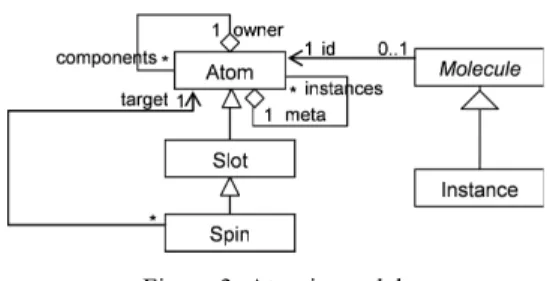
The descriptive layer sets the foundations of the coevolutive execution model. It provides the building blocks of the system. By convention, any element of the system is described using undividable units, called Atoms. Taken separately atoms do not have additional meaning. The business semantics will only emerge from their values and their composition. We call this model “atomic model” by analogy with the ancient Greek atomic model (Figure 3).Figure 3: Atomic model
An Atom represents (at most) one element of the system and holds its identity. It always references a meta Atom, which holds the identity of the element describing the structure and behavior of its associated element, even if at this stage we don’t know how to interpret the structure. An Atom has a collection of Slots. A Slot represents a primitive valued property (string, integer, etc…). The Spin is a particular type of Slot. Its value is a reference to an Atom.
Pursuing the atomic metaphor, Atoms can be composed arbitrarily to build more complex constructs, called Molecules. An Instance is a particular molecule that represents an object in the Class-Object paradigm.
In order to be correctly interpreted and validated (structurally and behaviorally), molecules must be typed.
Let us consider the Figure 4 below, representing a simple view on the M2 abstraction layer – where Class and Attribute are classes. Could they be represented using atoms and molecules?
Figure 4: M2 layer – Class and Attribute classes.
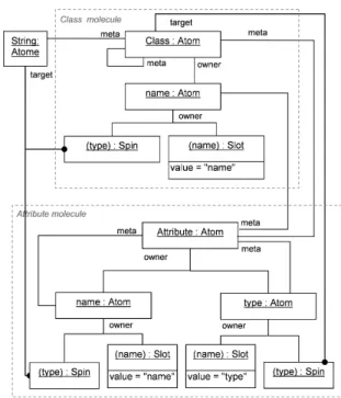
An atomic and molecular solution is depicted in Figure 5 below. The Class class is an instance of itself, and the attributes of the Attribute class are instances of Attribute.
The « instance of » relationship is concretized in the atomic model by a “meta” relation between the Atom representing a given object and the Atom holding the identity of its class.
Finally, the Class and Attribute classes are interpreted as typed molecules aggregating necessary atoms. The aggregation between the
representation in the Figure 5, for sake of readability.
Figure 5: Atomic and molecular representations of the Class and Attribute classes
4.1.2 Operational semantics layer
In order to make the model executable theClass and Attribute classes should be equipped
with operational semantics. The operational semantics should express how a particular atomic assemblage must be interpreted and transformed into a programmatic molecular construct, e.g. how to reconstruct the Figure 4 from Figure 5.
Thus, the meta relation is equipped with an instantiation semantics defined by the simple rules below (Table 1). T is the transformation operation
that creates a molecule from an atom. A is the set of atoms present in the system. instanceof is an
operator defined at the molecular level, returning
true if the second operand is a representation of the
first operand in the upper abstraction level.
Table 1: Instantiation rules
(1) ∀ a2
∈
A ∃! a1∈
A : a2.meta=a1 (2) ∀ a1, a2∈
Aa2.type='Atom' and a2.meta=a1 and a1.meta=Class
⇔ T(a2) instanceof T(a1) (3) ∀ a1, a2, a3, a4
∈
AT(a2) instanceof T(a1) and
T(a3) instanceof T(a4) and a1.meta=Class and
a4.meta=Attribute and a3.owner=a2 and a3.type='Slot'
⇔ T(a2)[a4.name] = a3.value
The operational semantics must then assert that the above rules are always respected. These constraints can be enforced when an instance of the
Molecule class is created (see Figure 3), or later
through explicit validation.
Although an additional layer is needed to specify this operational semantics, it can be added afterwards. Thus, meta-modeling activity can be decomposed into two distinct phases: (i) assemble the atoms, giving them a form that reflects the foreseen semantics, (ii) give the assemblages an explicit semantics and behavior through the operational layer that can be refined later dynamically.
If atomic structural requirements change, the operational semantics must be revised as well to consider the structural modifications. This is possible because the definition of the operational layer is dynamic. Both operational semantics specification and specific behavior implementation are represented as model operations and as such decomposed into Atoms as well.
Also, since all abstraction layers have an atomic representation, they all coexist. So the system as a whole becomes causally connected, i.e. any change made to the self-representation of the system is immediately reflected in its actual state and behaviour, as defined in (Maes, 1987).
4.2 Persistency and evolution
We are finally able to consider the persistency of atoms and molecules, and how their coevolution is supported.
As every element of the system is ultimately represented as an atom, it is possible to use a uniform solution to store the meta-meta-model, all meta-models, all models, and all terminal instances as mere data in a relational database.
For instance, atoms, as well as slots and spins (as described in Figure 3) can be stored in a unique table. In any case, this database has a fixed schema. This remarkable property eliminates common problems due to schema evolution and data migration. As a consequence, restarting and redeploying the system is no longer mandatory.
Moreover, querying and manipulating data and models become uniform and can be expressed at the atomic level. Thus, specific semantics must be used in order to interpret the atoms. For instance,
since there is no Employee table anymore, the evaluation of a query like select * from Employee must be adapted.
Therefore, the system can run continuously while still evolving.
4.3 Tracing the evolution
The database is extended with a traceability mechanism, based on the Karma and DBV models (Section 3.3). Thus not only the current state but also all the previous states of the database are available in conjunction with the user operation traces. The database states – successive as well as alternative – are organized as a global version tree (Cellary and Jomier, 2000). The database is therefore multi-version. Each version of the database, called global version, can be considered as a consistent mono-version database and contains at most one version of each atom. In the Karma traceability model, any elementary evolution creates a new system state automatically, derived from the previous state. Each local version of a given Atom is marked with the global version identifier where the evolution occurs. Therefore, it becomes easy to extract any previous state using a version identifier.
It is also possible to derive explicitly an alternative branch from a given global version. Finally, any given previous state of the database can be recovered instantaneously by selecting the corresponding version identifier in the version tree. Molecules are always assembled from appropriate Atom versions in a given global version of the database. A system state is based on a given database version. Thus, its atoms and molecules remain consistent. Since models are composed of Molecules as well and considered as mere data (and are treated as such), they are also intrinsically versioned. That means that all the abstraction layers – M0, M1, and M2 – benefit in the same way from the multi-version properties.
Some radical evolutions like splitting or merging elements can alter the molecular identity. Even in this case, traces and versions help detecting and avoiding inconsistencies.
Finally, not only the system can run continuously while evolving, but its entire history is recorded and the evolution can follow different branches. A continuum of design and execution lifecycle phases is thus achieved as long as every resource is in fine equipped with an atomic representation. Then the version substitution principle can be applied and the system can improve continuously.
5. IMPLEMENTATION
5.1 General architecture
The atomic model presented above has been implemented as an integrated modeling platform, based on JavaEE. The user interface paradigm follows the single-page web application style, as defined in (Mesbah and van Deursen, 2007). The platform allows the stakeholder and the developer to create models that can be dynamically instantiated. Their meta-models can also be refined dynamically. Any modification is propagated immediately all the way to target data.
The meta-model executability is achieved through a bootstrap phase during which the system operational semantics is dynamically injected, using a script. Two different implementations of the bootstrap script have been written (in Javascript and in Python) and can be run concurrently on the server side (JSR-223).
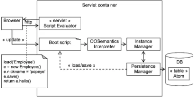
Figure 6: Implementation: architecture overview
Significant modifications of the meta-model might need to be reflected in the bootstrap script, so the script must remain modifiable dynamically.
Figure 6 sketches the environment architecture and interactions. Let us suppose the user wants to execute a simple script that instantiates the
Employee class. Users interact with the application
using standard internet browsers and specify the operation to be executed remotely (as a script). First, the bootstrap script is evaluated to create the required execution context. Then, the user action is executed on the server side. This is necessary in order to transform a Molecule into a python or javascript object through a SemanticsInterpreter component and to address it in a way that makes functional sense. SemanticsInterpreter delegates the Molecule construction to the InstanceManager component. Therefore, from a developer perspective, the Molecule structures are hidden behind scripted proxies, as illustrated in section 5.2.
Every scripting object that has an underlying molecular description (section 4.1.1), wraps its corresponding Molecule (Java) instance; any read or write operation applied on such a scripting object is redirected to its Java counterpart. This also allows adding strong typing to usually loose typed languages (i.e. Javascript or Python).
The Karma model has been implemented at two different levels.
–
In the database: additional tables have been created to store the global versions and the branches; the Atom table has been changed to a view in order to generate Atom versions transparently. Finally a set of stored procedures has been introduced to navigate through the timeline and the global version tree.–
In the application framework: an API has been added at the Java side and in the bootstrap script to enable global version selection. Application specific behavior, as well as meta-model behavior, is implemented through class operations, which are instances of the Operation class. Thus, operations are also considered as mere data. Their body is stored in a Text column. Their dependencies can then be detected both statically, by parsing their body, and dynamically, by automatically collecting their execution traces, explicitly managed by the Karma model.5.2 Example
The solution implemented on top of the proposed model covers the scenario presented in Section 2, as illustrated in Figure 7 and Figure 8 – those are screenshots of a scripting console embedded in the actual platform.
Figure 7: Employee instance creation
First the Employee class and its instance called
popeye are created and made persistent. At this
stage, the hello method is called on the instance
popeye. The result is shown on Figure 7. Then the Person class is created and the Employee class is
redefined as a specialization of Person (by setting its “super” attribute). Next, the nickname attribute is moved under the Person class and the show
method is dynamically updated. Finally the instance is loaded again and its salary is raised. Figure 8 shows the result of calling again the hello method on the Popeye instance.
Figure 8: M0-M2 layers coevolution
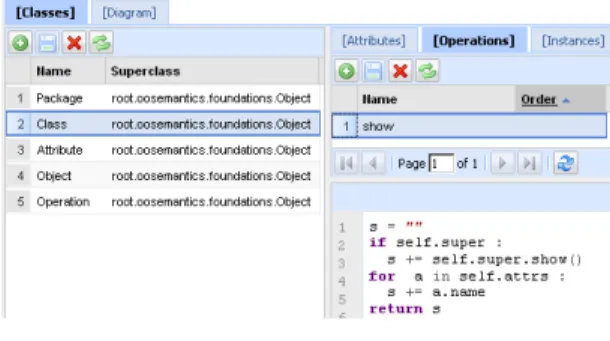
Meta-model evolution is illustrated Figure 9, ci-dessous through the update of the show method of the Class class. This evolution doesn’t change how Atom constructs are interpreted and thus doesn’t require reconsidering the bootstrap phase (although the introduction of the inheritance concept does).
Figure 9: show operation
6. CONCLUSION
This article introduces a coevolution support for reflective meta-models and their instances, tightly integrated into an MDE execution platform. Any system element is decomposed into undividable units, called atoms, allowing a homogeneous representation of any element, regardless its abstraction level.
To illustrate our approach we chose to reproduce the Class-Object paradigm. While the Class-Object approaches mainly stand at the conceptual level, Atoms and Molecules constructs are introduced at a lower abstraction level to allow refining (meta-)models without having to alter the underlying storage structure.
Atomic representation of both models and their instances are stored in a shared multi-version database. Since models and instances coexist as high-level atom constructs, their coevolution is managed in a consistent way, and model evolutions
are instantly reflected into their instances, making the whole system causally connected.
The prototype we implemented allows stakeholders, developers and final users to define, update and run models and theirs instances concurrently. It has been experimented in a multi criteria decision aid (MCDA) platform called
DECISIONDECK. Practitioners design formal MCDA
methods using basic user interface to edit and visualize input data. Although more formal evaluation is needed the preliminary results are encouraging.
However, our solution implies a development paradigm shift, and as such requires appropriate tools. We need now to focus on the development environment in order to support the usual industrial constraints of quality and productivity. These enhancements will be implemented in the next version of the system mainly as molecular constructs and will become a part of its karma.
7. REFERENCES
Agrawal, R. et al. 2009. The Claremont report on database research Commun. ACM 52, 6 (Jun. 2009), pp. 56—65
Ambler, S. W. and Jeffries, R. 2002 Agile Modeling: Effective Practices for Extreme Programming and the Unified Process. John Wiley & Sons, Inc. Breton, E. and Bézivin, J. 2001. Towards an
understanding of model executability. In Proceedings of the international Conference on Formal ontology in information Systems - Volume 2001 (Ogunquit, Maine, USA, October 17 - 19, 2001). FOIS '01. ACM, New York, NY, 70-80
Cellary W., Jomier G., 1990. Consistency of Versions in Object-Oriented Databases. VLDB, Brisbane: 432-441
D'Ambros, M., Gall, H., Lanza, M., and Pinzger, M., 2008. Analyzing software repositories to understand software evolution. In Mens, T. and Demeyer, S., editors, Software Evolution, chapter 3, pages 39--70. Springer.
Dinu, V., Nadkarni, P., 2007. Guidelines for the effective use of entity-attribute-value modeling for biomedical databases. Inernational .Journal. of Medical.Informatics, 76(11-12), 769—779
Ducasse S., Gîrba T., Kuhn A., Renggli L., 2009. Meta- Environment and Executable Meta-Language using Smalltalk: an Experience Report. In Journal of Software and Systems Modeling (SOSYM). February, 2009. Volume 8, Springer Verlag, pp. 5—19. Grubb, P., Takang, A. A. 2005. Software Maintenance
Concepts and Practices. World Scientific, second edition.
Hemel, Z., Kats, L. C., and Visser, E. 2008. Code Generation by Model Transformation. In Proceedings of the 1st international Conference on theory and Practice of Model Transformations (Zurich, Switzerland, July 01 - 02, 2008).
Vallecillo A., Gray J., Pierantonio A., Eds. Lecture Notes In Computer Science, vol. 5063. Springer-Verlag, Berlin, Heidelberg, 183-198.
Hôßler, J., Soden, M., Eichler, H.: Coevolution of models, metamodels and transformations, 2005. In Bab, S., Gulden, J., Noll, T., Wieczorek, T., eds.: Models and Human Reasoning. Wissenschaft und Technik Verlag, Berlin (2005), pp. 129—154 Johnson, R., Wolf, B.: Type object. In Martin, R.C.,
Riehle, D., Buschmann, F. 1998. Pattern Languages of Program Design, Addison Wesley ISBN:0-201-31011-2
Lehman, M. m. 1998. Software's Future: Managing Evolution, 1998. IEEE Softw. 15, 1 (Jan. 1998), 40-44. DOI= http://dx.doi.org/10.1109/MS.1998.646878 Maes, P. Computational reflection. 1987. Ph.D. 1987.
Thesis, Laboratory for Artificial Intelligence, Vrije Universiteit Brussel, Brussels. 1987
McKee, J.R. 1984. Maintenance as a function of design. In Proceedings of AFIPS National Computer Conference, pp. 187—193.
Mellor, S. J. and Balcer, M. 2002. Executable Uml: a Foundation for Model-Driven Architectures. Addison-Wesley Longman Publishing Co., Inc. Mesbah A., van Deursen A., Migrating Multi-page Web
Applications to Single-page Ajax Interfaces, 2007. Delft University of Technology SERG, Netherlands, TUDSERG-2006-018
Nadkarni P. et al., 1999. Organization of heterogeneous scientific data using the EAV/CR representation. Inernational. Journal of Medical. Informatics 6:478—93.
OMG, 2001. Architecture Board ORMSC. Model driven architecture (MDA). OMG document number ormsc/2001-07-01, available from www.omg.org, July 2001.
Renggli, L., Ducasse, S., Kuhn A., 2007. Magritte — A Meta-Driven Approach to Empower Developers and End Users, In Model Driven Engineering Languages and Systems, Ed. Gregor Engels, Bill Opdyke, Douglas C. Schmidt and Frank Weil, September, LNCS, Volume 4735, Springer, pp. 106—120. Van Deursen, A., Visser, E., Warmer, J., 2007,
Model-Driven Software Evolution: A Research Agenda. In Proceedings 1st International Workshop on Model-Driven Software Evolution (MoDSE 07),
Wachsmuth, G., 2007, Metamodel adaptation and model co-adaptation. In ECOOP 2007: Object-Oriented Programming, pp. 600—624. Springer
Zamfiroiu M., Jomier G. La traçabilité du processus de conception en génie logiciel, 1999, INFORSID’99, La Garde, France.