HAL Id: pastel-00877545
https://pastel.archives-ouvertes.fr/pastel-00877545
Submitted on 28 Oct 2013HAL is a multi-disciplinary open access
archive for the deposit and dissemination of sci-entific research documents, whether they are pub-lished or not. The documents may come from teaching and research institutions in France or abroad, or from public or private research centers.
L’archive ouverte pluridisciplinaire HAL, est destinée au dépôt et à la diffusion de documents scientifiques de niveau recherche, publiés ou non, émanant des établissements d’enseignement et de recherche français ou étrangers, des laboratoires publics ou privés.
Effects of surface chemical treatment on silicon negative
electrodes for lithium-ion batteries: an in situ infrared
spectroscopic study
Daniel Alves Dalla Corte
To cite this version:
Daniel Alves Dalla Corte. Effects of surface chemical treatment on silicon negative electrodes for lithium-ion batteries: an in situ infrared spectroscopic study. Materials Science [cond-mat.mtrl-sci]. Ecole Polytechnique X, 2013. English. �pastel-00877545�
Thèse présentée pour obtenir le grade de DOCTEUR DE L’ECOLE POLYTECHNIQUE
Spécialité: science des matériaux
Par
Daniel ALVES DALLA CORTE
Sujet
Effets du traitement chimique de la surface d'une
électrode négative en silicium amorphe pour batterie
lithium-ion: étude par spectroscopie infrarouge in situ
Soutenue le 4 octobre 2013 devant le jury composé de:
Danielle GONBEAU DR CNRS – UPPA Rapporteur
Bernard LESTRIEZ MCF-HDR Univ. Nantes – IMN Rapporteur Philippe MARCUS DR CNRS – Chimie ParisTech Examinateur Jean-Marie TARASCON Professeur – UPJV Président du jury Christian JORDY Ingénieur Dir. Recherche – SAFT Examinateur François OZANAM DR CNRS – École Polytechnique Directeur de thèse Michel ROSSO DR CNRS – École Polytechnique Examinateur
2
GENERAL INTRODUCTION
Lithium-ion battery has brought high-energy density, good power performance and no memory effect into the world of portable energy storage devices; nowadays it has become the main power source in mobile electronics applications. Even though it has allowed a great evolution in the field of energy storage, lithium ion battery has not considerably improved its capacity of energy storage since its first commercialization by Sony in 1991. With the constant development of high energy consuming portable devices, the field of energy storage systems searches for a breakthrough technology which will help to fulfill the need for high energy density batteries. In this case, silicon offers the possibility of a significant improvement in the energy density of anode materials, reaching a specific capacity about ten times higher than the typical carbonaceous electrodes present in most of the commercial lithium-ion batteries.
However, when silicon is submitted to a massive lithiation, it undergoes an intense volume expansion which results in a poor capacity retention with along the cycle life. The main strategy to overcome such problems is the use of nanosized silicon geometries. On the other hand, with such a geometry, the surface area of the electrode is maximized and consequently all the surface related side reactions increase. Therefore, the important role played by the solid electrolyte interphase on the performance of lithium-ion batteries becomes an essential factor to be controlled for the development of silicon based electrodes.
The present project started in this context, at the initiative and with the support of SAFT Company. During the internship of A. Kocan, in 2008, preliminary results suggest that silicon surface modification could have a positive impact on the electrochemical performance of amorphous thin film electrodes for lithium-ion batteries.1 The applied surface treatments were consisting in the creation of monomolecular layers by covalent grafting to the silicon surface. It has therefore been decided in the framework of the present thesis to make a detailed study of those aspects using an in situ analytical technique. For that purpose, coupling of infrared spectroscopy to the electrochemical environment of Li-ion systems has been at the core of the present work. This has been achieved in a geometry of
attenuated total reflection using thin-film electrodes. The present report is then organized in
3
In the first introductive chapter, some experimental issues associated to the studies on thin-film silicon electrodes are specifically addressed. These aspects could be at first considered as more or less trivial issues, but they are actually crucial in order to obtain significant, reproducible results. The second chapter is devoted to surface chemical treatments. Various molecular species have been grafted on amorphous silicon surface, and the electrochemical impact of these surface modifications has been closely looked at during the first lithiation/delithiation cycle. The third chapter is devoted to in-situ studies by infrared spectroscopy under electrochemical control. A special attention has been put on the characterization of the SEI layer, for electrodes with a surface modified according to some of the surface treatments previously investigated, and for two different electrolytes. The last chapter is aimed at differentiating between surface phenomena responsible for irreversible processes in Li-ion system, on which surface treatments may have an impact, and bulk phenomena which also contribute to these irreversible processes. For that purpose, a-Si0.9(CH3)0.1:H, a promising material with a bulk composition modified as compared with a-Si:H, has been considered.
4
Acknowledgments
Firstly, I would like to express my gratefulness towards François Ozanam, Michel Rosso and Thierry Gacoin who jointly advised me over the last years. I was very fortunate to have their support, guidance and friendship. I am also deeply thankful to Ionel Solomon who encouraged me in different aspects of this work.
I am deeply indebted to Christian Jordy and Georges Caillon. Their knowledge and support strongly contributed in this work. Additionally, they were very patient and tolerant with this scientific adventure.
I would also like to thank you Viacheslav Kubytskyi, Nguyen Le Thang Long, Lucie Devys and Jongwook Kim whom I have benefited from discussions of all sorts, for your friendships and support. I am also deeply thankful to all the members of the laboratory for all the care and help. You helped in making these years of work and study a pleasant journey.
Finally, I would like to thank my parents and French family whose love and support have brought me to where I am today.
5
Summary
1 – SILICON AS ACTIVE ANODE MATERIAL FOR Li-ION BATTERIES 8
1.1 – Introduction to Li-ion batteries 8
1.2 – Silicon based Li-ion electrodes 10
Silicon volume expansion upon lithiation 11
Solid electrolyte interphase formation in Li-ion anodes 12
Amorphous silicon thin films 15
1.3 – Electrochemical characterizations 16
Electrochemical characterization of a-Si:H thin films 16
Cell design and substrate influence on the irreversible charges 18
1.4 – Conclusion 24
2 – SURFACE TREATMENTS 26
2.1 – Introduction to surface treatments on electrode materials 26
2.2 – Molecular grafting 27
FTIR applied to grafting characterization 28
Hydrogenated surface 29
Surface methylation 33
Decene grafted surface 36
Undecylenic acid grafted surface 41
Polyethylene glycol grafted surface 44
Combined grafting of undecylenic acid and polyethylene glycol 48
2.4 – Discussion 51
6
3 – IN SITU FTIR 57
3.1 – Introduction to in situ ATR-FTIR study 57
3.2 – FTIR as a tool for studying Li-ion electrodes 58
3.3 – In situ ATR-FTIR characterization 62
SEI formation 63
Si-H consumption 70
The role of the surface pretreatment 73
The role of electrolyte composition 82
SEI thickness estimation 88
Reconstructed SEI spectrum 95
Bulk lithiation 97
3.4 – Conclusions 103
4 – BULK METHYLATED a-Si:H AND CHARGE DIFFERENTIATION 108
4.1 – Bulk methylated amorphous silicon – a:Si0.9(CH3)0.1:H 108
Characterization and electrochemical performance 109
In situ FTIR of methylated amorphous silicon 112
4.2 – Irreversible charge differentiation 114
Analytical method 114
The role of surface and bulk on the irreversible charges 116
4.3 – Conclusion 119
5 – GENERAL CONCLUSIONS AND PERSPECTIVES 120
Appendix A – Experimental procedures of molecular grafting 124
Appendix B – Principles of Fourier transform infrared spectroscopy 126
Appendix C – Attenuated total reflection geometry 129
7
Silicon as active material
for Li-ion batteries
Chapter 1
This chapter briefly introduces the principles of Li-ion batteries, demonstrating the challenges on the development of silicon based anode materials. It also reveals important experimental requirements in the study of thin film electrodes.
8
1 – SILICON AS ACTIVE ANODE MATERIAL FOR Li-ION BATTERIES
1.1 – Introduction to Li-ion batteries
The development of new mobile electronics has regularly increased in the last few years. With the competitive market of smartphones, tablet PCs and electrical vehicles this trend will increase in the following years. This new era of communications and mobility would not have been possible without energy storage solutions to power these mobile devices.
Among a wide range of energy storage systems, secondary electrochemical accumulators are currently the dominant technology for powering portable devices, mostly due to their capability of delivering electrical energy with high power density and rechargeability. This is the case of lithium-ion batteries, which were first commercialized by Sony in 1991 and represented a breakthrough in terms of energy density and high operating voltage.2
A lithium-ion system consists of an electrochemical cell containing a positive and a negative electrode separated by an ionic conductor electrolyte. Metal oxides are often employed as active materials for the positive electrode and the negative electrode usually consists of carbon. The electrolyte is imbibed in a porous separator which also acts as a physical barrier avoiding the contact between electrodes but allowing for transporting Li+ ions. Under discharge, lithium ions flow
spontaneously from the negative to the positive electrode through the electrolyte. During charge, the ions move in the opposite direction flowing from the positive to the negative electrode, as demonstrated in Fig. 1. Safety issues related to the growth of lithium dendrites and the risk of internal short-circuit on Li-metal batteries contribute to the development of the so-called Li-ion technology, which have both positive and negative electrodes based on Li hosting
9
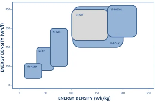
The quantity of electrical energy that a battery is able to deliver is a function of the cell potential (V) and capacity (mAh g-1), which are related to the intrinsic property of the materials that form the cell electrodes. Energy density is generally expressed per unit of mass (Wh kg-1) or unit of volume (Wh l-1). Fig. 2 represents the energy density of different battery technologies. The evolution of electrochemical energy storage systems can be identified along the improvement on energy density.3,4
Fig. 2 – Volumetric and gravimetric energy densities of different battery technologies.
Despite the evolution of energy storage achieved by developments on electrochemical accumulators, the capabilities of lithium battery technology are constantly being challenged by the modern multifunctional portable devices which are increasingly requiring higher performance in terms of power density. Energy storage was not able to improve with the same rate as the electronic industry progress.
10
1.2 – Silicon based Li-ion electrodes
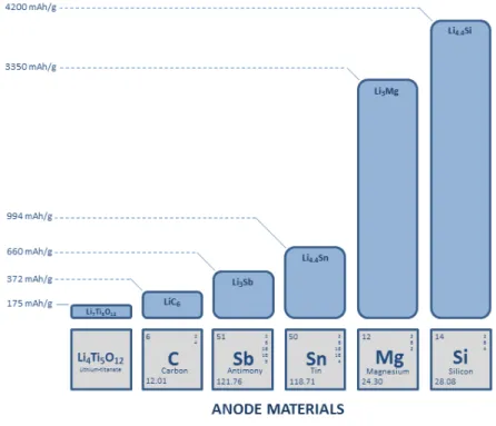
Lithium-ion batteries play an important role in power supplies for portable devices in a wide range of applications, with a great need for improvement in the energy density of the current energy storage devices. In this case, for an effective development of high energy density batteries, the development of high capacity electrode materials, for both positive and negative electrode, is an essential factor. Regarding negative-electrode materials, in general, commercially available systems are based on graphite anodes with a theoretical specific capacity of 372 mAh g-1.
Fig. 3 – Theoretical specific capacity of main anode materials for Li-ion batteries.
As shown in Fig. 3, the specific capacity of carbon is relatively low when compared to promising anode materials. Among them, silicon has been appointed as an important material for the next generation of Li-ion batteries. The use of silicon as negative-electrode material can represent a high improvement in energy density on Li-ion batteries due to its high specific capacity and the low charge/discharge potentials. As compared to graphite, silicon can store a much higher amount of lithium, reaching a theoretical specific capacity of 4200 mAh g-1.5 It is about 10 times higher than the current technology. Besides, silicon is an abundant element on earth and with technological processes well developed for the industry of semiconductors.
11
Silicon volume expansion upon lithiation
The high specific capacity of silicon comes from its alloying reaction with lithium, which allows for insertion of up to 4.4 atoms of lithium per atom of silicon. Such a massive quantity of lithium inserted into silicon has harmful consequences to the hosting structure. A metallic Li atom has a radius of 2.05 Å, which is far higher than those of the commonly studied host atoms (Sn: 1.72 Å, Si: 1.46 Å, Sb: 1.53 Å, Mg: 1.45 Å). Because of this steric constrain, a lithiated material will always develop a larger volume than the original unlithiated one. A full lithium insertion into silicon leads to a volume expansion of about 300%.6
The volume change of silicon is not dependent on its original structure: both amorphous and crystalline silicon are submitted to similar levels of stress during cycling. As sketched in Fig. 4 the atomic theoretical volume varies nearly linearly during lithiation/delithiation, proportionally to the content of inserted lithium. The values presented in Fig. 4 are strictly applicable for crystalline systems described by the Li-Si phase diagram,7 however a great similarity of volume expansion is expected for amorphous silicon.
Fig. 4 – Crystal structure, theoretic capacity and volume per Si atom for the Li-Si system.
Crystalline silicon undergoes phase transitions during lithiation, resulting in an amorphous structure after complete delithiation, the so called electrochemically-driven solid-state amorphization phenomenon.8,9 However, deep silicon lithiation at room temperature leads to a silicon amorphization until approximately a limit of 60 mV vs Li/Li+
12
and a composition of Li7Si2 is reached. Beyond this limit a crystalline Li15Si4 phase is produced.10 Pursuing silicon lithiation beyond this limit makes the process not totally reversible, since lithium cannot be completely extracted from Li15Si4. Upon delithiation, this crystalline phase turns into an amorphous LixSi phase (with x between 1 and 2) which is responsible for a partial irreversible charge.10 Therefore, in order to avoid the formation of the irreversible Li15Si4 phase we will avoid the use of deep lithiation limits in most part of the electrochemical tests performed in this work. In this case, we assume that once the Li15Si4 phase is not formed, the theoretical specific capacity value for silicon is 3590 mAh g-1, which will be taken as a reference value for all the calculations of specific capacity presented here.
A large volume change in the active material during cycling results in loss of mechanical integrity, cracking, pulverization and the disconnection of the active particles from the conductive current collector.11,12 The breakdown of the conductive network between active particles and current collector can be evidenced by the rise of the internal resistance.13 In the case of silicon, compressive stresses are experienced during lithiation as a result of volume expansion. However, initiation and propagation of cracks are normally promoted by tensile stresses instead of compressive stresses. Such phenomena occur during delithiation, where the contraction of silicon results in large tensile stresses, leading to cracking.14 All these facts contribute to the isolation of lithiated silicon particles, where the delithiation reaction was not completed. In consequence, the electrical access of these residual particles becomes impossible contributing to the irreversible capacity increase encountered on silicon electrodes.
Despite all detrimental consequences from volume change in silicon, important volume changes upon cycling are also faced by the most efficient and popular electrochemical systems – Acid and Ni-Cd batteries. The negative electrode in Lead-Acid batteries (Pb/PbSO4 reaction) undergoes a volume change of 120%, while the negative electrode of Ni-Cd batteries (Cd/Cd(OH)2 reaction) is submitted to volume expansion of 130%. It exemplifies that the volumetric expansion is not an irremediable drawback and that electrode processing and additives are key issues for the success of an emerging system.6
Solid electrolyte interphase formation in Li-ion anodes
In a first approach, the electrochemical processes present on lithium ion batteries appear to be quite simple, basically consisting on reversible exchange of lithium ions between two electrodes. However, in practice the operation of this electrochemical system encompasses more complex aspects.
Lithium-ion batteries work at voltages that are beyond the electrochemical stability of the main organic solvents present in the electrolyte. This high voltage enables such
13
batteries to deliver high power as well as to promote the reduction and decomposition of the electrolyte. During the first charge of a Li-ion battery, the electrolyte undergoes reduction at the negatively polarized electrode. This process occurs at the interface between electrode and electrolyte at low potentials, consuming charge and lithium ions in an irreversible way. The product of this reaction is basically a mixed layer of Li2CO3, lithium alkyl carbonates, lithium alkoxides and other salt by-products (e.g. LiF for electrolytes based on LiPF6 salt); all these species form the so-called solid electrolyte interphase (SEI). Fig. 5 sketches the gradual formation of the SEI by the electrochemical reduction of the electrolyte all along the surface between active electrode material and electrolyte. This decomposition layer is mainly formed at the beginning of the lithiation process, especially during the first cycle.
Fig. 5 – Scheme of SEI formation on Li-ion electrodes.
Two competitive reaction mechanisms have been proposed for the electrochemically induced reduction of electrolytes based on carbonated solvents. As shown in Fig. 6, one possible reaction path (reaction I) leads to the formation of a Li2CO3 rich SEI layer, with ethylene as a co-product. It is believed that this reaction results in a weakly stable SEI. Another possible reaction path (reaction II) leads to the formation of lithium alkyl carbonate, with a smaller amount of gaseous products, yielding a more stable and compact SEI layer.15
Different studies observed that electrode morphology and surface chemistry can affect these two mechanisms, leading to the preferential formation of one of the two species. This preferential effect associated with the electrode characteristics was specifically confirmed for graphite electrodes where the SEI composition of basal planes was found to
14
be rich in organic products, while the prismatic edge of the graphite structures developed an inorganic composition.16,17 This gives evidences of the role played by the surface properties on the SEI composition and consequently its effects on the passivation properties. Therefore, by controlling the species present on the electrode surface one can tailor the SEI composition in order to obtain improved passivation properties.
Fig. 6 – Reaction mechanisms for SEI formation.
Even though SEI is formed from the electrolyte partial decomposition and could be thought to be detrimental to the electrode processes, the properties of this layer are unique and play an important role in the entire Li-ion system. The SEI is in first approximation permeable to lithium ions and rather impermeable to other electrolyte components and electrons. The characteristics of the SEI layer formed at the electrode/electrolyte interface can influence the kinetics of lithiation/delithiation and the interfacial stability during prolonged electrochemical cycling. Also, it offers a reasonable protection for electrolyte compounds from further decomposition and prevents electrode from corrosion.18
The cycling capability and lifetime in Li-ion batteries are dependent on the nature of the interfaces between electrodes and electrolyte, whereas safety is a function of the stability of the electrode materials and interfaces. Therefore, the performance and safety of Li-ion batteries are intrinsically related to the features of the SEI layer present in the system.
Having in mind the importance of the SEI on the performance of the Li-ion batteries, some electrolyte additives are used to intentionally react during cell operation and chemically coat the active materials with an organic film. Vinylene carbonate (VC) is part of a group of reduction-type electrolyte additives, where the presence of one or more polymerizable carbon-carbon bond makes possible its reduction during cell operation. VC is electrochemically reduced prior to electrolyte solvents, forming an insoluble solid product which decreases the subsequent electrolyte decomposition. The high reduction efficiency of VC makes its presence sufficient for stabilizing the SEI layer even at small concentration (1 to 2 wt.%).15 In the case of silicon active material VC is responsible for a smooth and uniform SEI formation, allowing for superior electrochemical performances.19
15
Another class of additives may not be reduced during cell operation but will act as a collector for the radical anions formed during the intermediate steps of the electrolyte reduction, or coupling agent with the final products of the SEI, assisting its stabilization.15 One example of such additives is mono-fluoroethylene carbonate (FEC). Under cell operation, such a compound it is responsible for producing smoother and more stable SEI in silicon electrodes, resulting in improvements in the reversible capacity and coulombic efficiency.20
Amorphous silicon thin films
The present study was achieved on silicon thin film electrodes, which constitute a simple system for studying the physicochemical effects of silicon lithiation. This configuration allows for getting more direct information on the silicon electrochemical evolution and electrode/electrolyte interactions, avoiding parasitic effects associated to binders or conducting additive materials. It also allows for using surface-characterization techniques in a well-defined geometry, providing more easily interpretable results.
Hydrogenated amorphous silicon thin film (a-Si:H) electrodes were prepared by plasma enhanced chemical vapor deposition (PECVD) in a low-power regime where silane (SiH4) molecules are decomposed to form a deposit on the surface of a heated substrate, as schematically shown in Fig. 7. Pure SiH4
precursor results in a hydrogenated amorphous silicon deposit, where part of the silicon bonds is passivated by hydrogen and where a substantial content of free atomic hydrogen is present in the material. When a mixture of silane and methane (SiH4/CH4) is used instead, methyl groups (CH3) are incorporated in the silicon network producing a so called methylated amorphous silicon deposit (a-Si1-x(CH3)x:H).21
The deposition is usually performed on 250oC heated substrates, with a pressure of 40 mTorr and a SiH4 flow of 2 L h-1. During the deposition, the SiH4 plasma is assisted by a 13.56 MHz radio frequency excitation delivering to the plasma a power of 0.10 W cm-2. These parameters result in a deposition rate of 3 nm s-1. The thickness of the electrodes was kept rather thin, varying from 10 to 200 nm, in order to prevent or decrease mechanical electrode degradation of the electrode due to the large volume change during electrochemical cycling and the associated loss of active material. Higher capacity retention
Fig. 7 – Schematic description of a PECVD chamber.
16
on amorphous thin films upon cycling can be achieved by decreasing the thickness of the film22 and/or increasing the methyl content concentration.23
1.3 – Electrochemical characterizations
At first sight, thin-film based electrodes offer ideal conditions for electrochemical measurements: the planar geometry allows the active surface to be accurately determined. The absence of binder or conductive additives gives intrinsic results related to the thin film material and improved resistance against fracture formation. However, thin-film geometry contains a very small mass of active material, which results in a low value of capacity per area of electrode. In the case of a 100 nm thick a-Si:H electrode (a typical value in the present work), assuming a density of 2.3 g cm-3 and a theoretical capacity of 3590 mAh g-1, the cell capacity can be estimated on 59.5 μAh. This value is extremely low, especially when compared with commercial cells (e.g. Sony 18650 cell with a nominal capacity of 2400 mAh).2 Working with such low capacity values makes any parasite reaction have important consequences on the charge values measured during cell operation. In order to identify and minimize the role played by experimental conditions on the charge consumed during electrochemical cycling, different experimental aspects were tested.
Electrochemical characterization of a-Si:H thin films
Galvanostatic cycling with potential limitation (GCPL) is a method for electrochemical evaluation of battery materials. This technique consists in applying a constant current to the electrochemical cell while its potential is monitored and kept between two potential limits. Each time a potential limit is reached the current is reversed and this procedure is repeated according to the chosen number of cycles. The time (t) under constant current (I) of each step of charge/discharge is used to determine the quantity of electrical charge (C) per mass of active material (m) of the tested material, as Eq. 1 describes. C is commonly expressed in mAh g-1 and represents the gravimetric specific capacity of the material.
17
Current density is another important parameter for battery testing. Here the current density is determined as a function of the cycling rate conventionally described as C/n, which means that a full charge or discharge of the cell is achieved in n hours. For example, assuming that silicon lithiation has a theoretical specific capacity of 3590 mAh g-1, a cell containing 1 g of silicon would charge or discharge in 1 hour using a current of 3590 mA. The same principle of calculation can be applied for thin film electrodes. Table 1 presents the values of capacity and current density calculated for thin film electrodes based on silicon theoretical specific capacity of 3590 mAh g-1, assuming a surface area of 0.72 cm2 and deposit density of 2.3 g cm-3 for a-Si:H.24
Table 1 – Theoretical capacity and current density* values of a-Si:H thin film electrodes.
Thickness (nm) C (μAh) C (mC) iC/1 (μA cm-2)
10 5.9 21.2 8.3 30 17.8 64.1 24.8 60 35.7 128.5 49.5 100 59.5 214.2 82.6 150 89.2 321.1 123.9 200 118.9 428.0 165.1
Silicon electrodes and associated lithiation and delithiation reactions represent the half-cell correspondent to the negative electrode in a lithium-ion system. However, for experimental purposes the silicon half-cell is assembled with a lithium half-cell, based on a metallic lithium electrode, where in this case silicon is considered as the positive electrode. Therefore, in a lithium-ion system silicon undergoes lithiation upon charge and delithiation during discharge or vice-versa when using a metallic lithium foil as counter-electrode in electrochemical half-cell.
During the first discharge, the electrolyte is reduced on the negative electrode triggering the SEI layer formation. Subsequently, silicon lithiation starts to take place as moving phase boundary in the electrode.25 This electrochemical lithiation is characterized by the plateau on the potential (E) versus specific capacity (C) plot, Fig. 8. After the lower potential limit is reached, silicon undergoes delithiation and the E vs. C curve exhibits a delithiation plateau. From the complete cycle, reversible (QREV) and irreversible (QIRR)
charges can be determined, as sketched in Fig. 8.
18
Fig. 8 – Typical electrochemical cycling of silicon.
Cell design and substrate influence on the irreversible charges
Another challenge for the study of thin film materials by electrochemical processes is to determine the surface of contact between the thin film and the electrolyte. The amount of electrochemical signal in a thin film configuration is entirely dependent on the surface area exposed to the electrolyte, highlighting the importance of a precise determination of this experimental parameter. Commercially available cell designs for battery applications are usually not well suited to the study of thin film electrodes. On these common cell designs, the control of the electrode surface in contact with the electrolyte is hardly reproducible. A precise way of certifying this contact area consists in using a standard electrochemical cell where the contact between electrode and electrolyte is achieved through an aperture. This type of electrochemical cell stores the electrolyte and keeps the distance between electrodes constant, avoiding the use of a separator, but at the expense of using a larger electrolyte volume. The coupling of the electrode and the cell is assured by an O-ring seal, enabling a constant area of contact and protecting the system against leakages.
Galvanostatic cycling with potential limitation (GCPL) was performed in different cell geometries in order to check the influence of the cell design on the electrochemical performance of thin film electrodes. Electrochemical experiments were carried out using 1M LiClO4 in propylene carbonate as electrolyte, a 30 nm thin film a-Si:H deposited onto stainless steel as working electrode, a lithium foil mounted on a copper current collector as counter electrode, a current density of 25 μA cm-2 and potential limits between 0.01 V and
19
2 V vs. Li/Li+. Bare stainless steel electrodes were also tested for the purpose of investigating the substrate effect on the electrochemical results.
Two cell designs were tested, one based on a commercially available cell typically employed for testing materials for Li-ion batteries (here called Swagelok-like cell) and the other one based on an O-ring sealed standard electrochemical cell. The first cell makes use of an electrolyte imbibed separator and does not offer any restriction for the excess of electrolyte present in the separator. In comparison, the O-ring sealed standard electrochemical cell offers a precise control of the contact surface between electrode and electrolyte.
As shown in Fig. 9a, the lithiation profile E vs. C of a-Si:H thin film electrodes depend on the cell design used for the experiment. The capacity values are shown in terms of mC in order to compare the results obtained for silicon electrodes with tests performed on bare stainless steel. These tests demonstrate that bare stainless steel react most irreversibly with lithium, representing a source of irreversible charge (gray line in Fig. 9a). In a Swagelok-like cell, schematically represented on Fig. 9b, the excess of electrolyte spreads inside the cell when it is sealed, increasing the area of stainless steel in contact with the electrolyte. This increases the amount of irreversible charge created by side reactions not related to the electrochemical processes on silicon active material. It is assumed that the enormous value of lithiation capacity measured for the thin film in the Swagelok-like cell (black line in Fig. 9a) is due to the contribution of the substrate and internal cell walls in contact with the excess of electrolyte. This problem cannot be minimized by decreasing the quantity of electrolyte present in the separator because, in such cell configuration, the use of a low quantity of electrolyte makes the wetting of the entire electrode surface critical. A reduced amount of electrolyte can also make the system become extremely sensitive to the pressure applied on the separator.
Using a standard electrochemical cell, as schematically represented on Fig. 9c, the lithiation feature of a-Si:H becomes similar to what is observed in the literature6 (blue line in Fig. 9a), with a capacity value close to the theoretical value (for a 30 nm thick a-Si:H deposit, a value of 80 mC corresponds to about 3700 mAh g-1).
20
Fig. 9 – Effect of cell designs on electrochemical performance of thin film based electrodes (a) performed in swagelok-like (b) or standard (c) electrochemical cells. a-Si:H electrodes are based on 30 nm thick deposits
with theoretical capacity of ≈64 mC (equivalent to 3590 mAh g-1).
Electrochemical measurements on thin film electrodes are also extremely dependent on the surface preparation of the substrates. Charge consumption due to SEI formation is proportional to the real surface area of the electrode. In this case, surface roughness of the substrate play an important role on the electrochemical measurements, justifying the importance of roughness control.
For the purpose of quantifying the roughness of stainless steel substrates, surface profiles were measured using a surface profiler (Dektak 150). On these measurements stainless steel button cells were also tested as one possible option of substrate. As shown in Fig. 10, pristine button cells and stainless steel plates exhibit high average surface roughness (Ra)† and important dispersion of results, represented by the standard deviation bars. A reduction in the results dispersion was achieved by simply polishing with emery paper (grain size of 15 μm). The minimal value of Ra and of its dispersion is obtained by polishing with diamond paste (grain size of 1 μm). Surface preparations not only decrease the substrate roughness but also decrease the dispersion of these values, contributing to the reproducibility of the electrochemical measurements.
† R
a – Average surface roughness: Arithmetic average deviation from the mean line within the assessment
21
Fig. 10 – Control of substrate roughness by different surface preparations.
Information related to the influence of cell design and substrate preparation on the electrochemical performance were taken into account to set the experimental conditions of the following work. Standard electrochemical cells with compartments containing about 1 ml and electrode apertures of 0.72 cm2 were used for the electrochemical characterization of most of the materials analyzed in this work. Galvanostatic cycling with potential limitation (GCPL) was performed in standard electrochemical cells, assembled in an Argon filled glove-box, using 1M LiClO4 in propylene carbonate as electrolyte and lithium foil counter electrodes, as previously described. Silicon based electrodes were prepared by depositing a-Si:H of different thicknesses on polished stainless steel substrates. GCPL measurements were performed inside a glove-box, current densities were calculated for cycling rates of C/10 with potential limits between 0.1 V and 2 V vs. Li/Li+.
Fig. 11 shows the first lithiation/delithiation cycles of thin film electrodes of a-Si:H with various thickness from 10 nm to 200 nm. For all the electrodes a lithiation plateau is reached at about 0.24 V vs. Li/Li+, which is related to the movement of the phase boundary between a-Si:H and a-SiLix:H during lithiation. It is in agreement with the lithiation potential observed for silicon nanoparticles.26 In the case of crystalline silicon the lithiation potential is expected to be lower, between 0.07 and 0.115 V vs. Li/Li+.25
The lithiation capacity is found to increase almost linearly with deposit thickness as expected. Irreversible capacity value is found to be weakly dependent on the deposit thickness, as it is expected if it corresponds only to the SEI formation. However, some
22
dispersion is observed. A close look at the beginning of the cycle (see insert in Fig. 11) reveals that some additional contribution is recorded before reaching the lithiation plateau for the thinnest deposits.
Fig. 11 – Electrochemical cycling of a-Si:H thin film electrodes. Labels indicate the thickness of the thin film deposit and the irreversible capacity as a percentage of the reversible one.
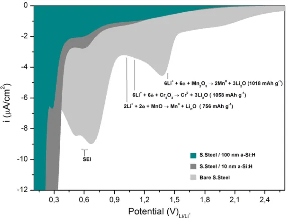
In order to identify the origin of these additional electrochemical reactions present on the thinnest electrodes during their first lithiation, cyclic voltammetry was used. It was performed on a-Si:H films deposited on bare stainless steel, with a thickness varying between 10 nm to 100 nm. The potential was scanned at 0.5 mV s-1 starting from open circuit potential until 0.1 V vs. Li/Li+. Cell assembling and characteristics follow the same parameters as those used for GCPL measurements.
23
Fig. 12 – Cyclic voltammetry of a-Si:H thin film electrodes and bare stainless steel electrode.
As shown in Fig. 12, a bare stainless steel electrode exhibits intense cathodic reactions. For potentials higher than 0.9 V vs. Li/Li+ the signal corresponds to lithium reactions with alloy elements present in stainless steel. Theoretically, lithium reaction with Chromium and Manganese oxides is responsible for charge consumptions from 758 to 1058 mAh per gram of oxide.27 However, the oxide conversion reaction undergoes a large irreversibility on the first cycle due to Li2O formation.28 Cathodic signals from 0.8 to 0.3 V vs. Li/Li+ correspond to the electrolyte reduction and SEI formation29, signals at lower potentials typically correspond to a-Si:H lithiation25,26 at the same time as SEI formation continues to take place. 30 Electrochemical lithiation of oxide species present in the substrate does not seem to play an important role on the electrochemistry of a-Si:H thin film electrodes. However, the intense electrochemical reactions detected for stainless steel at potentials around 0.6 V vs. Li/Li+, corresponding to SEI formation, is shown to be also present on the 10 nm-thick electrode and to become very weak for the 100 nm thick one. It demonstrates that stainless steel influence the absolute value of the irreversible charge on very thin electrodes, suggesting the presence of pinholes in the deposits.
24
1.4 – Conclusion
Along this first chapter it has been explained how electrochemical experiments on thin-film materials differ from conventional powder based electrodes in several aspects. At first, the modest quantity of active material decreases the ratio between lithium electrochemical reactions with silicon and parasite reactions. It makes the charge consumed on electrochemical reactions between substrate and electrolyte, often negligible in usual systems, become an important source of irreversibility. In this case, cell geometry can play an important role on the precision and relevance of the electrochemical results. It was demonstrated that Swagelok-like cells are not suited to perform electrochemical measurements on thin film electrodes and that a standard O-ring sealed cell is appropriate for such experiments. Besides, in thin-film geometry, the mass of active material is also dependent on the surface preparation of the substrate. Controlling the substrate roughness insures the precise control of the amount of active material and increases experimental reproducibility.
It was finally shown that silicon thin films deliver a great specific reversible capacity under electrochemical cycling. In average, about 2800 mAh g-1 was reversibly obtained during the first cycle, operating with a relatively high limit of lithiation (0.1 V vs. Li/Li+) and at room temperature. A high irreversible charge during the first cycle was also observed, which has been found to be weakly dependent on the electrode thickness. For the thinnest samples the contribution of the substrate to the irreversible capacity of the electrode may have to be considered, due to the presence of pinholes in the deposit.
25
Surface treatments
Chapter 2
In this chapter we explore the possibilities of surface modification of silicon by the grafting of different chemical species in order to limit some detrimental effects of the SEI layer. Grafting characteristics and electrochemical performances of amorphous silicon electrodes are investigated for determining the passivation properties of such molecular layers.
26
2 – SURFACE TREATMENTS
2.1 – Introduction to surface treatments on electrode materials
As a boundary between active electrode material and electrolyte medium, the electrode interface plays an important role in the performance of the entire electrochemical system. This interface is not only the starting point for lithium permeation into silicon, but also where most of the side reactions responsible for the SEI formation take place. The characteristics of this frontier can impact the kinetics of lithium permeation and the physicochemical properties of the SEI layer.
Naturally formed SEI layer may present an inhomogeneous nature, suffer from partial detachment during cycling and make use of a certain amount of charge during its formation, for which charge is irreversibly consumed for electrolyte reduction during the first cycles.31 The development of a designed molecular layer, which might be viewed as an artificial inner part of the SEI, can offer an alternative to limit the main disadvantages of a natural SEI. Engineered solid electrolyte interphases may minimize the detrimental reactions associated with the electrode-electrolyte interface, which is the critical part of any electrochemical system.3
However, surface modifications on electrode materials must take into account structural and volumetric changes of the electrode during lithiation. Ideally, a stable passivating SEI layer that tolerates or recovers rapidly when damaged by the changes in the electrode volume would improve its lifetime and reduce irreversible charge possess. At the same time, this idealistic SEI must allow for a fast lithium ion transfer between the electrode-electrolyte interface. Simple treatments, such as non-covalent coatings or depositions, have a weak bonding with the active electrode material, limiting their stability. Covalent attachment of organic molecules offers a robust coating for electrode materials. Moreover, if the layer formed by covalent grafting to the surface does not exhibit lateral reticulation between grafted moieties, it is expected to be stable through cycling.
Covalently linked molecular monolayers are a current way of surface modification of silicon substrates, complementing and/or extending the applications of relevant technological materials toward, for example, the development of molecular devices and well-defined sensing interfaces.32 There exists numerous methods of surface modification by molecular grafting, however, when it comes to the field of energy storage, diazonium chemistry is one of the most usual.33,34 The electrochemical reduction of diazonium salt generates an organic radical which can attach to the electrodes surface via a covalent bond,
27
providing an artificial SEI layer composed of at least one molecular monolayer. This method of surface grafting was essentially employed on carbon surfaces where electrochemical performance of graphite based electrodes can be improved by the grafting of polysiloxane35, nitrophenyl36 or lithium benzoate37 multilayer films. Additionally, molecular grafting represents an alternative for improving electronic conductivity of Li-ion electrodes by directly bonding the active material into a conductive matrix38 or by making use of the grafted layer as a precursor for a conductive carbon coating39.
Surface chemistry can deeply affect the electrochemical processes in lithium-ion batteries by modifying the mechanisms of SEI formation, leading to layers with different chemical compositions and passivation properties. However, it may happen that a modified surface induces the formation of SEI layers with properties for blocking not only the continuous electrolyte reduction, but also the transfer of lithium ions through the electrode surface, resulting in harming the performance of the entire electrochemical system. In the case of silicon nanowires, the surface coating by methyl or siloxane species leads to highly passivating SEI layers, hindering the bulk lithiation and resulting in weak capacity values.40
2.2 – Molecular grafting
Grafting of organic species can be reached by various possible routes and using several chemical schemes different from diazonium chemistry. Silicon offers significant possibilities for a direct covalent Si-C bond, allowing for surface functionalization by innumerous functional groups. Surface modification, or the so claimed artificial SEI, can be tailored on different aspects according to the grafted component. Such a wide range of possibilities makes necessary the adoption of an experimental strategy. In this work, linear organic molecules were electrochemically or photochemically grafted on amorphous silicon electrodes in order to establish an artificial SEI layer. Grafted species were varied in order to explore the effects of surface covering density, chain length and functional group termination.
In an important number of molecular grafting cases, surface covering density and molecular chain length are correlated. This correlation is based on the fact that once one molecule is grafted into a surface atomic site it can decrease the probability of a second molecule being grafted in the surrounding atomic sites by steric hindrance effect. This exclusion effect is more effective when the grafted chain is longer and the chain density increases. On the other hand, there are cases where the grafted molecule actually helps grafting the subsequent molecules by creating a new active site for grafting in its close vicinity. When steric hindrance is exceeded or avoided, the dense attachment of molecules leads to the formation of a polymeric brush, with a maximized steric barrier effect. 41,42
28
FTIR applied to grafting characterization
Fourier transform infrared spectroscopy (FTIR) is an important tool for studying materials at the molecular level. Infrared radiation can be partially absorbed at specific frequencies corresponding to their vibrational resonances, which allows for identifying functional groups by the vibrational signature of their chemical bonds.
Infrared spectra are obtained by detecting the changes in the transmitted intensity across a probed sample, as a function of the wavenumber. When computed as an absorbance, the intensity of the analyzed signal is linearly correlated to the amount of the probed species present in the sample.43 In order to enhance the detection sensitivity, the attenuated total reflection (ATR) technique is often used. Such a method makes use of a waveguide crystal allowing numerous reflections to take place between the infrared beam and the sample surface. For each reflection, the infrared beam probes the medium adjacent to the prism along a penetration depth, which corresponds to the spatial extent of the evanescent wave associated with the infrared electric field. This geometry is frequently used for the characterization of molecular grafting, where organic species can be directly grafted onto the ATR crystal. This principle was used here for analyzing the characteristics of molecular layers directly grafted on a thin amorphous silicon layer deposited on the surface of the ATR crystal, as schematically sketched in Fig. 13. Considering the small thickness of the amorphous silicon layer (few
nanometers) and its optical similarity with the Si (111) ATR crystal, the presence of the amorphous layer does not introduce sizeable losses for FTIR analyses, hence it does not restricts the applicability of the method. On the opposite, it provides us with a surface environment similar to that used for the electrodes in our experiments. The principles of FTIR and ATR techniques are explained in detail in appendix B and C.
The different surface chemical states associated with the grafted organic monolayers were here characterized by ATR-FTIR spectroscopy using a Bomem MB100 spectrometer, equipped with a liquid-nitrogen-cooled HgCdTe (MCT) photovoltaic detector. Such an experimental configuration provides a wide spectral range for the analysis, from ~980 cm-1 to 4000 cm-1. The spectra recorded after surface modifications were compared to that taken before grafting, providing the absorbance change with respect to the hydrogenated amorphous silicon surface.
29
Hydrogenated surface
A native layer of silicon oxide of 1-2 nm of thickness is expected to be formed on the surface of the as-deposited amorphous silicon layer once it is exposed to air.44 Therefore, grafting of organic monolayers on oxide-free silicon surfaces by wet chemical routes necessarily starts with the chemical etching of the silicon oxide layer and the saturation of the exposed surface bonds.
Surface hydrogenation is the usual passivating agent present at the surface after oxide removal from silicon surfaces. Alternative strategies of surface passivation can be obtained relying on halogens such as iodine or chlorine.45,46 Hydrogen-terminated silicon surfaces can be prepared by chemical etching in fluoride-containing solutions. This type of hydrogenation became an attractive procedure for surface preparation because of its ease of preparation, relative stability in air and during brief time in water, and due to the lack of appreciable reactivity toward a range of common solvents (including acetonitrile, diethyl ether, chlorobenzene, hexane, toluene and mesitylene).32
The silicon etching in hydrofluoric acid was originally thought to lead to a fluoride terminated surface due to the high strength of the Si-F bond (≈ 5.0 eV).47 Schematically, the high electronegativity of fluorine is used for removing the oxygen atoms from the silicon surface by replacing Si-O bonds by Si-F. Back bonds of the fluorinated silicon atoms will then become strongly polarized due to the electronegativity of F, allowing for the silicon atom dissolution by insertion of a HF molecule in the polarized bond, which results in leaving Si-H termination at the surface, as sketched in Fig. 14. This mechanism results in a hydrogen-terminated surface.48 A more complete picture should take into account the role of water species, especially OH- ions.49,50
Fig. 14 – Simplified scheme of the mechanism of silicon oxide stripping and silicon hydrogenation by HF in aqueous solution. Notice that the final products of the etching are actually SiF62- ions.
In this work, all the amorphous silicon deposits were exposed to air after the deposition process. All the samples were taken out from the deposition chamber at air
30
contact before being cooled and stored in an Argon filled glove-box. Therefore, the surface of pristine deposited layers is covered with a thin native oxide film.
Oxidized silicon surfaces are easily identified by FTIR. SiO2 typically exhibits three infrared absorption bands, common to all the polymorphs and located at frequencies in the range of 480 cm-1, 800 cm-1 and 1100 cm-1. These infrared signals correspond respectively to Si-O bending modes, symmetric and asymmetric stretching modes of Si-O-Si units.51 However, the asymmetric stretching vibration mode is very sensitive to the oxygen stoichiometry of the oxide and can vary linearly with the oxide composition. SiOx oxides (x ≤ 2) exhibit vibrational frequencies varying from 1075 cm-1, for a stoichiometric oxide, decreasing until 940 cm-1 for oxides with low oxygen content. 52,53,54 In amorphous SiO
2 the disorder-induced mechanical coupling of the transverse optically active oxygen asymmetric stretch at 1076 cm-1 with the longitudinal optically inactive oxygen asymmetric stretch are responsible for generating the infrared absorption shoulder observed between the 1076-1256 cm-1.55,56
Deoxidized surfaces were obtained by sample exposition to HF vapor for 10 s. This technique has found to be efficient for removing most of the oxidized species from the surface of amorphous silicon thin films. Fig. 15 demonstrates that even an intensively oxidized surface (oxidized in a H2O2:H2SO4 (1:3) solution) can be almost completely re-hydrogenated by HF vapor exposition. Notice that the hydrogen content of the HF-vapor treated surface is similar to that of the surface immersed in HF solution and that only a minute amount of oxide is detected at the HF-vapor treated surface.
Fig. 15 – ATR-FTIR of oxidized and HF vapor treated a-Si:H surfaces. Both spectra referred to the surface hydrogenated by immersion in HF solution.
31
All the spectra in Fig. 15 are referred to the spectrum of the same amorphous silicon deposit hydrogenated by immersion in a HF concentrated solution for 1 s. This wet treatment leads to a complete surface hydrogenation, but also represents a risk of excessive silicon etching, especially for amorphous silicon, and corrosion for metallic substrates. The use of etching by HF vapor avoids such a risk of chemical dissolution, but it also leads to some surface contamination with Si-F.57
The intense signals of SiOx stretching vibrations (1000 – 1300 cm -1) present on the oxidized surface practically disappear after HF vapor hydrogenation. By comparing the integrated values of band intensities, it appears that the oxide content was decreased to about 8% after hydrogenation. Moreover, HF vapor is capable of yielding a surface covered by Si-H bands (revealed by the absorption peak at ~2100 cm-1) in the same amount as those present in the reference hydrogenated spectra.
The electrochemical performance of all the surface-modified amorphous silicon layers described in this chapter were tested by recording one electrochemical cycle. For this purpose, a 30 nm thick layer of a-Si:H was deposited on mirror polished stainless steel substrates submitted to the different experimental process of surface grafting described in the appendix A. Electrochemical tests were performed in O-ring sealed electrochemical cells using 1M LiClO4 in propylene carbonate as electrolyte and lithium foil mounted on a copper current collector as counter electrode. Galvanostatic cycling with potential limitation (GCPL) was performed at the rate of C/10, based on the theoretical value of capacity calculated for the 30 nm thick a-Si:H layer (17.8 μAh) and an exposed surface of 0.72 cm2. The potential was limited from open-circuit voltage (OCV) to 0.1 vs. Li/Li+ during silicon lithiation and from 0.1 vs. Li/Li+ to 2.0 vs. Li/Li+ during delithiation. A systematic study of different experimental parameters was performed in the first chapter, and resulted in an optimized testing setup which allows for good reproducibility of the electrochemical results presented here.
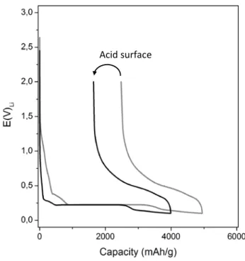
The results of electrochemical tests demonstrated the positive effects of surface hydrogenation on the performance of amorphous silicon based electrodes. As shown in Fig. 16, the removal of surface oxides decreases the charge irreversibly lost during the first electrochemical cycle. This can be experimentally evidenced by comparing the values of lithiation and delithiation capacities measured for hydrogenated samples (black line) and for pristine layers (gray line). The hydrogenation decreases the lithiation capacity by 100 mAh g-1, the irreversible capacity by 520 mAh g-1, increases the coulombic efficiency by 10% and decreases the irreversible capacity (calculated as a percentage of the reversible capacity) by about 32%. In both cases the electrochemical cycling presented similar aspects, such as electrolyte decomposition starting from about 1.3 V vs. Li/Li+ with an intensive SEI formation from 0.4 V vs. Li/Li+, and a lithiation plateau at 0.230 V vs. Li/Li+. The high values of lithiation capacities, exceeding the theoretical value of 4200 mAh g-1, demonstrate that the charge is being used not only for silicon lithiation but also for side electrochemical reactions, such as the electrolyte decomposition.
32
It therefore appears that surface hydrogenation not only is necessary for the directly covalent grafting of organic molecules into silicon but also can play an important role on the lithiation and delithiation processes. Even though the pathway and final products resulting from the conversion of the native oxide layer by reacting with lithium are still uncertain, the presence of the oxide layer has consequences on the electrochemical performance of silicon based electrodes, as shown in Fig. 16. The SiO2 reduction expected from Eq. 2.1 is assumed to be kinetically impossible.58 However, SiO2 can be converted to silicate forms according to Eq. 2.2 and Eq. 2.3.59
SiO2 + 4Li+ + 4e Si + 2Li2O (2.1) 5SiO2 + 4Li+ + 4e Si + 2Li2Si2O5 (2.2) 2SiO2 + 4Li+ + 4e Si + Li4SiO4 (2.3)
The presence of the native oxide layers on the surface of electrode materials could therefore contribute to the initial irreversible capacity through its electrochemical reduction. It could also represent a barrier for bulk lithiation, since SiO2 is a Li-ion insulating material. This might avoid the complete lithiation of the silicon electrode, decreasing the specific capacity and increasing the interfacial charge transfer impedance.59
Fig. 16 – Electrochemical cycle of a-Si:H deposits on steel substrates. Hydrogenated surface (black line) and pristine surface (gray line).
33
Surface methylation
A perfect passivation of all the silicon atomic sites present on the surface of a silicon crystal is only possible by hydrogen termination. However, hydrogenated surfaces exhibit limited chemical stability, being oxidized under normal conditions of pressure and temperature. Stable grafted layers are often obtained by molecular grafting of long molecules, however the Van der Walls radius of molecular chains prevents the complete surface passivation due to steric hindrance between adjacent grafted units, regardless the chemical strategy used for the grafting. As a noticeable exception, the methyl group is one of the few species with a size compatible with a complete saturation of all the surface silicon dangling bonds.60 The distance between silicon surface sites on Si(111) surfaces is 3.8 Å, while the van der Waals radius of a methyl group is ca. 2 Å. The later value seems slightly too large for making a complete substitution of all surface Si-H bonds possible. However, a proper orientation of the neighboring methyl groups makes such a substitution possible and complete methylation of the silicon surface has been demonstrated.60
In the present work, silicon surface methylation was obtained by anodic treatment in organic anhydrous electrolyte composed of 3M CH3MgI in diethyl ether. Detailed experimental procedures are presented in the appendix A. The surface methylation starts from the hydrogenated silicon surface and first requires the breaking of Si-H bonds, which is obtained either by anodization at positive enough potentials or through anodic generation of organic radicals and further reaction of these radicals with the surface. The resulting silicon dangling bonds can then be grafted in the presence of a second radical according to different reaction paths, as summarized by the following reactions, where h+ stands for silicon hole: 61
≡Si● + CH3● ≡SiCH3 (2.4) ≡Si● + CH
3MgI + h+ ≡SiCH3 + MgI+ (2.5) ≡Si● + CH
3– + h+ ≡SiCH3 (2.6)
The reactions described in 2.4-6 allow for achieving a complete surface methylation in flat atomic surfaces of crystalline silicon.61 However, when the surface morphology is modified, for example in porous silicon, the efficiency of molecular substitution of hydrogenated silicon by methyl groups decreases to about 80%.62 It is therefore expected that surface methylation applied to amorphous silicon surfaces results in a large but incomplete Si-H substitution.
34
Fig. 17 presents the ATR-FTIR spectrum of a methylated amorphous silicon layer. The grafted layer can be identified by the deformation modes of the methyl group at 1255 cm-1 for symmetric deformation and 1410 cm-1 for asymmetric deformation, and the stretching modes at 2900 cm-1 for symmetric stretching and 2960 cm-1 for asymmetric stretching.60 Besides the surface methylation, residual contamination from the grafting reactants and oxides can be identified by the extra peaks in the ATR-FTIR spectrum. It is likely due to the fact that some cleaning steps had to be avoided due to possible corrosive effects for samples based on stainless steel substrates, such as rinsing in HCl for Mg(OH)2 removal as suggested in previous works.60
Fig. 17 – ATR-FTIR of methylated a-Si:H surface, referred to the hydrogenated surface in HF vapor.
Direct quantitative evidence of methylation was obtained by comparing the integrated values of the band intensities of the Si-H vibration modes centered at 2100 cm-1 before and after the grafting procedure. It was possible to determine that the surface methylation was responsible for a consumption of 55% of the hydrogenated sites. However, part of the Si-H consumption is maybe due to surface oxidation during the anodic process of grafting under trace impurities. Small trace of such oxidation, sometimes observed, is totally absent from the spectra plotted in Fig. 17, which does not exhibit any oxide-related feature in the 1000-1200 cm-1 range. All in all, it might be considered that the methylation efficiency is limited to a value of ~ 50%, larger than the grafting efficiency of longer molecule chains (see here after) but specifically lower than the figure reached on crystalline or porous silicon.
35
Electrochemical tests show that surface methylation has a negative impact on the electrochemical performance of the amorphous silicon layers deposited on stainless steel substrates. Fig. 18 shows that the grafting treatment increases the charge irreversibly consumed during the first electrochemical cycle. The comparison between capacity values obtained for the methylated a-Si:H electrode (black line) and for the pristine layers (gray line) shows that the lithiation capacity
increases by 255 mAh g-1 and the irreversible capacity increases by 340 mAh g-1 for the grafted samples. The electrode methylation decreases the coulombic efficiency by about 5% and increases the irreversible charge by 18% as scaled to the reversible charge. Furthermore, the shape of the electrochemical cycling curve is modified for the methylated electrodes. As for a pristine layer, the electrolyte decomposition starts from about 1.3 V vs. Li/Li+, however, for methylated surfaces an intensive reaction is observed from about 0.8 V vs. Li/Li+; this extra reaction is no more discernible when the lithiation potential is reached.
Even though surface methylation leads to a decreased electrochemical performance, when compared to the pristine case, the results indicate that the capacity values here obtained were close to the theoretical value expected for silicon. The effect of surface methylation was clearly related to the introduction of new chemical species into the electrode processes resulting in additional sources of side reactions and consequently increasing the amount of irreversible capacity. Our results are substantially different from the results observed elsewhere for silicon nanowires,40 where the surface methylation was responsible for passivating the electrode, with undesirable consequences for the capacities values. In the case of silicon nanowires, the surface modification results in a reversible capacity of 538 mAh g-1 in the first electrochemical cycle. Taking into account that the surface area of electrodes based on nanowires increases the role played by the surface phenomena during cell operation, we can assume that part of the difference in the electrode performances is related to the reduced degree of surface methylation and the presence of contaminants observed in our experiments.
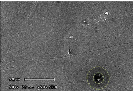
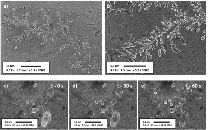
The superficial aspect of all the grafted electrodes studied in this work has been investigated by scanning electron microscopy (SEM). After completing one electrochemical cycle the samples were removed from the cell in an Argon filled glove-box, rinsed in fresh
Fig. 18 – Electrochemical cycle of a-Si:H deposits on steel substrates. Methylated surface (black line)
and pristine surface (gray line).
36
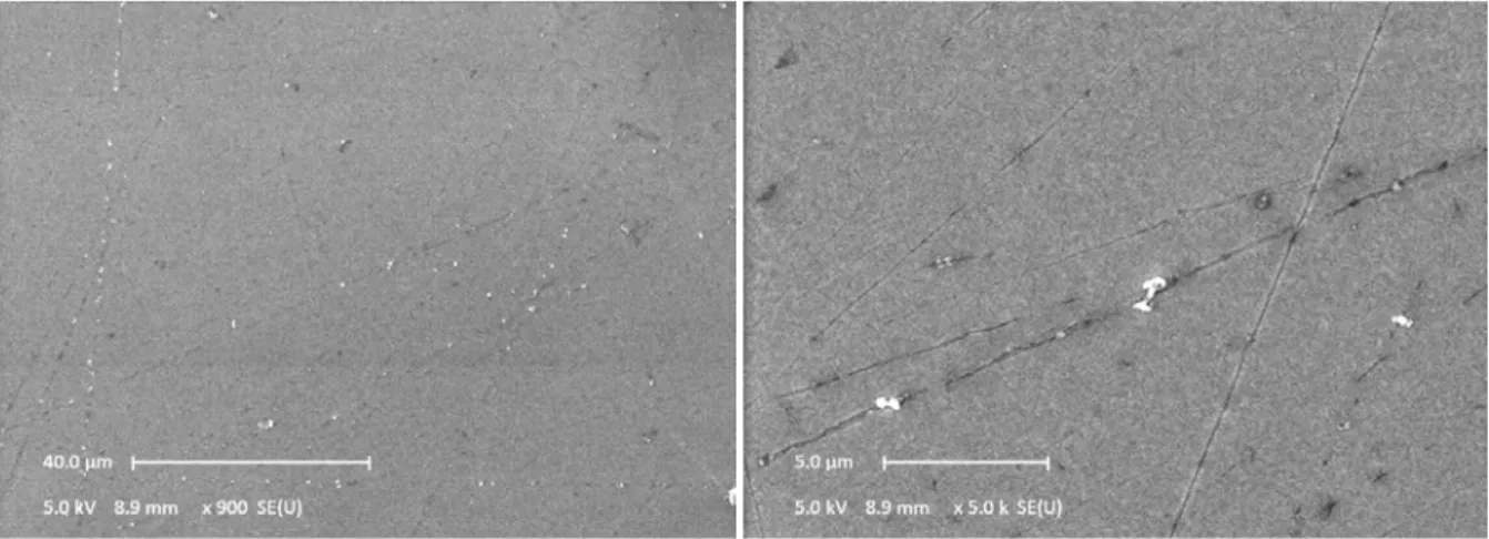
anhydrous propylene carbonate, rinsed in anhydrous dimethyl carbonate, vacuum dried and stored in the glove-box. The SEM images were taken from samples directly brought from the glove-box in a protected atmosphere, being exposed to air only when installed in the microscope chamber. The SEM analysis does not show any important modification of the surface with the grafting procedure or with the electrochemical cycling. As shown in Fig. 19, methylated a-Si:H electrodes present a very smooth surface with the presence of some few structures. Some of them identified as probable traces of electrolyte rising, white spots of about 500 nm in the Fig. 19. Additionally, the presence of zones of higher contrast having 4 μm of diameter is observed. At the center of these zones an emerging structure (circular mark on the figure) possibly results from an inhomogeneous lithiated spot or concentrated SEI formation due the presence of surface contaminant.
Fig. 19 – SEM image of a methyled a-Si:H electrode after the first electrochemical cycle.
Decene grafted surface
Longer chains can be obtained by alternative (non electrochemical) techniques, which offers a better limitation of unwanted surface contamination, and the possibility of designing a thicker artificial SEI layer. Decene can be covalently bonded to silicon atoms with a high grafting density of about 6 molecules per nm2, offering an important blocking property.63 The application of such a molecular coating in lithium-ion batteries can allow for producing an artificial passivation layer that could reduce the need of electrolyte decomposition for the formation of a natural SEI. This strategy can increase the chemical stability of anode materials in contact with electrolytes, reducing the irreversible charge losses and resulting in more efficient electrochemical systems.
37
The grafting of decene is performed on oxide-free hydrogenated silicon surfaces by hydrosilylation, a radical-induced reaction which can be initiated either by free radical initiators, visible or ultraviolet light, or thermal activation.32,64,65 The cleavage of the Si-H bond can be effectively photoinduced by 350 nm photons, a fact that makes UV light an attractive reaction initiator.66 Grafting of decene on hydrogenated silicon starts with a photoinduced surface activation which is followed by the nucleophilic attack of an alkene. The reactions 2.7-9 describe the grafting mechanism, where the first reaction is the UV initiation followed by the propagation of the radical induced by the grafted molecule.
≡Si-H + hν ≡Si● + H+ (2.7)
≡Si● + CH2=CH(CH2)7CH3 ≡Si–CH2CH2(CH2) 7CH3● (2.8)
≡Si-H + ≡Si–CH2CH2(CH2) 7CH3● ≡Si–CH2CH2(CH2) 7CH3 + ≡Si● + H+ (2.9)
Such a reaction scheme is still debated and probably oversimplified, but the final surface product has been characterized.32
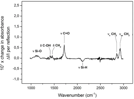
Qualitative and quantitative information about decene grafting on silicon surfaces can be obtained by ATR-FTIR measurements. The infrared signature of decene species grafted on silicon consists of the vibration modes of CH2 scissoring at 1460 cm-1, CH2 symmetric stretching at 2852 cm-1, CH2 asymmetric stretching at 2925 cm-1, CH3 symmetric stretching at 2880 cm-1 and CH
3 asymmetric stretching at 2955 cm-1. As shown in Fig. 20, all the characteristics vibration modes of decene were found in the the ATR-FTIR spectrum obtained for the grafting of decene on amorphous silicon. Moreover, a small signal of non-stoichiometric oxides is also observed at wavenumbers below 1075 cm-1.
38
Fig. 20 – ATR-FTIR spectrum of amorphous silicon layer grafted with decene, referred to the hydrogenated surface in HF vapor.
The concentration of surface grafted species was determined from a truly quantitative study of the infrared signature of decene, where the CH vibration signals were fitted by using a model consisting of a linear baseline and Voigt functions as described in reference 70. The absorbance signal characteristic of the symmetric stretching vibration mode of CH2, positioned at about 2850, was used to estimate the total surface density of CH2 species present on the silicon surface. The results were compared to the calibration values obtained from the infrared cross section of the same CH2 vibration mode in dodecane, giving origin to an equation which relates the infrared absorption signal of νsCH2 with its surface concentration on silicon. Assuming that each decene molecule is composed of nine CH2 groups, one can estimate the decyl chain surface concentration. In the present work, the decene grafting on a-Si:H surfaces resulted in surface concentration of decyl chains of 2.9 x 1014 cm-2, estimated from the analysis of the infrared spectrum shown on Fig. 20. This value is close to the one obtained for grafting in atomically flat Si(111) surfaces, estimated to 3.1 x 1014 cm-2.70
Quantitative analyses, having the peak areas calculated for oxidized surfaces as a reference, leads to the conclusion that oxidation during decene grafting does not overcome 2% of the initial hydrogenated sites. Taking into account that 92% of the surface was efficiently hydrogenated by HF vapor, the total oxide content on the decene grafted surface does not exceed 10% of the surface.