Titre:
Title
:
Resistance welding of thermoplastic composites with a
nanocomposite heating element
Auteurs:
Authors
: David Brassard, Martine Dubé et Jason R. Tavares
Date: 2019
Type:
Article de revue / Journal articleRéférence:
Citation
:
Brassard, D., Dubé, M. & Tavares, J. R. (2019). Resistance welding of
thermoplastic composites with a nanocomposite heating element. Composites Part B: Engineering, 165, p. 779-784. doi:10.1016/j.compositesb.2019.02.038
Document en libre accès dans PolyPublie
Open Access document in PolyPublie
URL de PolyPublie:
PolyPublie URL: https://publications.polymtl.ca/4101/
Version: Version finale avant publication / Accepted versionRévisé par les pairs / Refereed Conditions d’utilisation:
Terms of Use: CC BY-NC-ND
Document publié chez l’éditeur officiel Document issued by the official publisher
Titre de la revue:
Journal Title: Composites Part B: Engineering (vol. 165)
Maison d’édition:
Publisher: Elsevier
URL officiel:
Official URL: https://doi.org/10.1016/j.compositesb.2019.02.038
Mention légale:
Legal notice:
Ce fichier a été téléchargé à partir de PolyPublie, le dépôt institutionnel de Polytechnique Montréal
This file has been downloaded from PolyPublie, the institutional repository of Polytechnique Montréal
Resistance Welding of Thermoplastic Composites with a
Nanocomposite Heating Element
David Brassarda,c, Martine Dubéb,c, Jason R. Tavaresa,c,∗ aDepartment of Chemical Engineering, Polytechnique Montréal, P.O. Box 6079 Station
Centre-Ville, Montréal, QC, H3C 3A7, Canada
bDepartment of Mechanical Engineering, École de technologie supérieure, 1100 Notre-Dame Street West, Montréal, Québec, Canada, H3C 1K3
cResearch Center for High Performance Polymer and Composite Systems (CREPEC), Polytechnique Montréal, P.O. Box 6079 Station Centre-Ville, Montréal, QC, H3C 3A7, Canada
Abstract
In this study, we propose a new heating element (HE) for the resistance welding of thermoplastic composites. This HE is made of polyetherimide (PEI), rendered electrically conductive by the addition of 10% wt. multi-wall carbon nanotubes (MWCNT) (conductivity of 0.79 S cm−1). The new HE were successfully used to weld carbon fibre/poly(ether ether ketone) (CF/PEEK) laminates in a single lap shear configuration, leading to a lap shear strength of up to 19.6 MPa. Observations of the fracture surfaces revealed a cohesive failure mode within the nanocomposite HE and non-uniform heating over the weld area. It is believed that PEI/MWCNT HE present an interesting alternative to current HE, although more work is needed to improve the temperature homogeneity over the weld area.
Keywords: Resistance welding; A. Polymer–matrix composites (PMCs); A. Thermoplastic resin; E. Joints/joining;
∗
Corresponding author
Email addresses: [email protected] (David Brassard),
1. Introduction
The current fierce competition in the space industry is putting a strong down-ward pressure on the launch cost of satellites. New processes and materials are needed to reduce launchers’ weight and cost. Fibre reinforced polymers are com-monly used to achieve weight reduction. Currently, thermoset polymers domi-nate the market for composite matrices but thermoplastic composites (TPC) are attracting the attention of the industry [1] because of their higher impact resis-tance, increased production rates, superior recyclability and higher environmental resistance [2]. Moreover, a distinct advantage of thermoplastics over thermosets is their ability to be joined by welding instead of adhesive bonding or mechanical fastening.
Different welding processes have been developed for various applications and joint geometry. Resistance welding, induction welding and ultrasonic welding are a few of the processes used for joining TPC. To weld the adherents (i.e. the parts to be joined) through traditional resistance welding (Fig. 1a), heat is generated by a porous and electrically conductive heating element located at the weld interface and connected to a power source. An electrical current is applied to the heating element to generate heat. The connection between the power supply and the heat-ing element is generally established by copper connectors that are clamped at a predetermined distance from the edges of the adherents (the so-called “clamping distance”). During the welding process, pressure is applied to the weld stack to achieve intimate contact and to promote autohesion during the melting and consol-idation phases.
The first heating elements that were used for the resistance welding process were made of carbon fibre [3–5]. Poor weld reproducibility and problematic elec-trical connections between the electrodes and the carbon fibres caused scaling
is-sues [6]. These shortcomings led to the use of stainless steel (SS) mesh heating elements that improved the consistency of the process [7].
The lap shear strength (LSS) obtained from single lap shear (SLS) specimens and failure modes are commonly reported to evaluate the performance of welded joints. For samples welded with SS heating elements under suboptimal conditions, adhesive failure (ADH) between the mesh and the polymer or between the poly-mer and the adherents is obtained. These failure modes can be accompanied by tearing of the mesh. Under good welding conditions, light-fiber-tear failure (LFT), often accompanied by mesh tearing, is observed [8]. Failure modes and LSS are dependent on the fibre nature and orientation within the adherents [9]. For mate-rials with lower performances, such as glass fibre and polyetherimide (GF/PEI), failure occurs in the adherents, but for high performance and stiffer materials, such as unidirectional carbon fibre and poly(ether ether ketone) (CF/PEEK) laminates, damage occurs in the heating element with little to no damage to the adherents [10]. The variations in the failure modes indicate that poor adhesive bonding between the polymer and the SS mesh [8, 11–14] can be a limiting factor under certain circum-stances. An increase in the fraction of open area of the SS mesh, to a certain extent, improves LSS. Concurrently, some concerns were expressed regarding the weight penalty of SS meshes [15].
Players from the space industry are looking at alternative heating elements. Their target is a low-density material that is not affected by corrosion. A conduc-tive polymer-based nanocomposite heating element, compatible with the adherents, could serve as that alternative and provide good interfacial bonding. Such nano-composites are formed by dispersing conductive nanoparticles (typically metal or carbon) into a polymer matrix. The electrical properties of nanocomposites de-pend, among other things, on the intrinsic properties of the nanoparticles, their mass fraction, surface modifications, and the mixing method employed. This was
illustrated by Bauhofer et al., who showed that the same kinds of particles can produce nanocomposites with widely different properties [16]. For applications such as resistance welding, we seek a conductivity sufficiently low to generate heat through the Joule effect but high enough to prevent current leakage through the adherents.
For traditional resistance welding of high performance TPC parts made of CF/PEEK, PEI is sometimes used to provide a resrich region at the weld in-terface. The miscibility of PEI in PEEK [17] also improves the bonding between the adherents to attain good mechanical performances. By using PEI for the matrix of the nanocomposite, we hypothesize that we could take advantage of that mis-cibility and obtain a nanocomposite heating element suitable for resistance weld-ing of CF/PEEK laminates while welding at temperatures lower than the melting temperature of PEEK (in a similar way to the Thermabond process [18]). This novel heating element would be almost entirely miscible within the matrix of the composite and does not leave metallic elements within the weld. Furthermore, the MWCNT/PEI coefficient of thermal expansion is better matched with that of CF/PEEK composites than pure PEI with a metallic insert. Therefore, it is believed that thermal residual stress can be reduced by the use of this nanocomposite HE.
This article presents the development of this new heating element for resistance welding of TPC with a PEI-based conductive nanocomposite. Joule heating of the nanocomposite is validated with a sample heating element. This new heating element is then used to join CF/PEEK adherents and their mechanical performance is evaluated by single lap shear tests.
2. Methodology 2.1. Materials
2.1.1. Polymers and Nanocomposite
The polymer used for the heating element development was PEI (CAS 61128-46-9) pellets ordered from Sigma Aldrich. PEI pellets had a melt index of 18 g per 10 min at 337◦C with a mass of 6.6 kg. GPC/SEC measurements of the molecular weight for this PEI gave a Mnof 15.0 kg mol−1and a Mwof 21.6 kg mol−1.
The conductive nanoparticles consisted of dry powdered MWCNTs, produced by combustion chemical vapour deposition (CCVD), purchased from Raymor In-dustries. They had outer diameters in the range of 10 to 20 nm, lengths from 1 to 12µm and purity of at least 99%.
Initial batches of nanocomposites with 5%, 10% and 15% wt. of MWCNTs were produced with a DSM Xplore 5 cc twin-screw micro compounder. Polymer pellets were introduced along with the MWCNTs and internally mixed by the re-circulation circuit. The resulting extruded wire was cut into pellets that were mixed and fed a second time to produce a uniform mix for each batch. The pellets were hot-pressed to produce 1.6 mm thick flat samples to measure their electrical con-ductivity.
The electrical conductivity of the PEI nanocomposites, at 5%, 10% and 15% wt. of MWCNTs, was measured with the four-point probe technique. A probe manufactured by Jandel engineering was mounted on a resistivity test rig from A&M Fell Ltd. and connected to an acquisition system composed of a Keithley 220 programmable current source and a Hewlett Packard 34401A multimeter. The tungsten carbide probes had a diameter of 0.4 mm, a radius of 100µm and a spacing of 1 mm.
The final batch of nanocomposite with 10% wt. of MWCNTs, for the manu-facturing of the heating elements, was produced in a twin-screw extruder and
pro-cessed at 340◦C. Polymer pellets were introduced along with the MWCNTs. The extruded wire was cut into small pellets, mixed thoroughly and fed back into the extruder two other times to obtain a uniform composition. The final wire was cut into pellets prior to further processing. Flat PEI nanocomposite heating elements, with a 10% mass fraction of MWCNTs, were produced by hot pressing pellets into 0.5 mm thick films and cutting them into rectangles of 12.7 mm × 55 mm.
2.1.2. Composite
The TPC adherents were produced by compression moulding CF/PEEK pre-impregnated plies to form unidirectional (UD) composite laminates and cutting them to dimensions (25.4 mm × 101.6 mm ), with an abrasive saw, according to ASTM D5868 - 01(2014). In agreement with the supplier’s recommendations, the stacks of plies were heated to 390◦C under a pressure of 0.25 MPa. The pressure was then increased to 1 MPa for 30 min to consolidate the laminate before cooling it back to room temperature in about 60 min. The pressure was maintained during the cooling phase.
2.2. Joule Heating of a Nanocomposite Heating Element
Prior to the welding tests, a simple validation of the heating elements was de-vised. A 0.5 mm thick PEI heating element, was installed in the welding setup and connected to electrodes 25 mm spaced apart. A constant DC voltage was then applied for 45 s. A FLIR T420 infrared camera was used to record the surface temperature distribution once an electrical current was applied.
2.3. Welding Experiments
A computer-controlled resistance welding jig was built to weld single lap shear specimens with an overlap of 12.7 mm and a width of 25.4 mm (Fig. 1). Two copper electrodes were used to connect the power source to the nanocomposite heating element. Three pneumatic actuators applied constant pressure over the two
electrodes and the welding zone, while the nanocomposite was kept between two composite adherents. The electrodes where connected to the heating element, on each side of the laminate (Fig. 1a) with the proper clamping distance for each test. Electrical power was supplied by a 10 kW programmable DC power source series XR from Magna-Power capable of providing up to 160 V and 60 A. The power source can be driven as a constant voltage source, constant current source or with custom power profiles. A modulation scheme was configured to allow the source to operate with a constant power output. In this mode of operation, the source adjusts its output current based on the voltage applied and keeps a constant power output, disregarding variations in the resistance of the heating element.
For the welding experiments, electrical parameters were set so as to closely mimic conditions that are observed during traditional resistance welding of TPC. The initial voltage setting for constant voltage operation was calculated based on a specific power of 350 kW m−2and the electrical resistance of the heating element.
Prior to welding, the surfaces of the adherents and the nanocomposite were cleaned with acetone. Once the heating element and adherents were installed in the welding jig, a contact pressure of 2.4 MPa was applied by the electrodes on the heating element, to minimize contact resistance. Over the weld area, a third actuator applied a constant pressure of 1 MPa during the whole welding process. It was previously demonstrated, for traditional resistance welding, that pressures close to 1 MPa are able to produce welds with good mechanical properties by pro-moting intimate contact, necessary for polymer chain diffusion at the interfaces, while preventing void formation due to excessive polymer flow out of the weld [3, 8, 11]. Type K thermocouples, located on the ceramic above the welded zone, monitored the temperature during the welding process (Fig. 2a). The thermocou-ples could not be installed directly on the nanocomposite heating element, as their presence altered the heat transfer mechanisms within the weld and Kapton® tape
was not sufficient prevent electrical interference. The first thermocouple was lo-cated slightly off centre at 14 mm from the edge of the adherent at the centreline of the overlap. The second thermocouple was also located on the centreline, but 2.5 mm away from the edge of the adherent. These two locations served as proxy to approximate the temperature within the weld. Closer to the heating element, a higher temperature is expected. Aside from the operating mode for the power source, the clamping distance and the duration of the welding process were the main factors taken into account during the welding tests.
2.4. Characterization of welded joints
The LSS of each weld was evaluated with a SLS test as per ASTM D5868 – 01(2014) with an MTS Alliance RF/200 testing machine. Subsequently, fractogra-phy analysis was carried out with ImageJ. In this analysis, dividing the area of the welded zone by the total area gave the percentage of welded area. Both faces of the fractured specimens were evaluated to get an average measure for each sample. The failure modes obtained were classified and reported as per ASTM D5573 – 99(2012).
2.5. FTIR Analysis
FTIR spectra were collected to validate the absence of thermal degradation due to the welding process. A Nicolet iS5 FTIR Spectrometer equipped with an iD5 at-tenuated total reflectance (ATR) module was used to collect spectra from the virgin PEI pellets and PEI nanocomposite films before welding, and PEI nanocomposite on the fracture surfaces after SLS tests. Spectra for CF/PEEK adherents were also collected to serve as reference.
3. Results and Discussion
3.1. Electrical Conductivity of the Nanocomposites
The electrical conductivity of PEI nanocomposites with 5%, 10% and 15% wt. MWCNTs was 0.27 ± 0.08, 0.79 ± 0.06 and 0.92 ± 0.30 S cm−1, respectively. It was decided that the marginal gain in conductivity between 10% and 15% wt. MWCNTs was not worth the increased cost and production problems associated with high particle loading (such as increased viscosity and brittleness). Thus, a PEI nanocomposite with 10% wt. MWCNTs was retained for manufacturing heating elements.
3.2. Micro-Mechanical Simulations of Joule Heating
During the initial development of the nanocomposite, finite element models were developed using COMSOL Multiphysics® to evaluate the contribution of the three main heating mechanisms inside the nanocomposite heating element (i.e. Joule heating of MWCNTs, from the concentration of charges at the contact points between MWCNTs and of the matrix between MWCNTs) and verify that the poly-mer will not undergo thermal degradation. A set of three continuum microme-chanic models presenting different contact topologies were used to assess the rel-ative contribution of each heating mechanism to the global heating phenomena within a conductive nanocomposite. The uniform temperature fields observed at the constituent level led to the conclusion that under normal operating conditions, local thermal degradation should not occur within the nanocomposite during the welding process and that Joule heating is the dominant mode of heat generation. The complete methodology and results for these simulations are included as Sup-plementary Information.
3.3. Joule Heating of a Nanocomposite Heating Element
At the beginning of the Joule Heating tests, a uniform temperature field is observed in the nanocomposite (Fig. 3b). For longer test durations, the copper electrodes are acting as heat sinks at the edges of the heating element causing a measurable temperature gradient (Fig. 3c to 3f). It was possible to control the surface temperature of the heating element with a variation of the voltage (Tab. 1). The voltages applied during this test were limited to try to stay below the glass transition temperature of PEI at 217◦C. These results validate the Joule heating behaviour of the nanocomposite heating element.
3.4. Welding Experiments
Small geometric variations of the nanocomposite heating elements (thickness and width) introduced variations of the electrical resistance. Because of this vari-ation, operation under constant voltage conditions achieved poor reproducibility between initial welding tests and was not investigated further. Operation under constant power yielded significant improvements in the consistency of welding re-sults, avoiding the effect introduced by the heating element electrical resistance variation.
3.4.1. Constant power welding
Tests were carried out at a specific power of 350 kW m−2with a constant pres-sure of 1 MPa on the weld. Clamping distances of 0, 1 and 1.5 mm and welding times of 60, 70, 90 and 120 s were investigated. Three samples were produced for each welding condition. The LSS along with the average fraction of welded areas are reported in Table 2.
Average LSS from 13 MPa up to 19.6 MPa were obtained. Longer weld times allowed the nanocomposite to melt and bind with the adherents over a larger
frac-tion of the welded zone. From the condifrac-tions tested, applying current for 120 s with a clamping distance of 1.5 mm yielded the best LSS results.
Cohesive failure within the nanocomposite was the primary mode of failure observed for samples welded under constant power with UD composite adherents. Some adhesive failure on the edges of the heating element was also observed. Sam-ples welded for 60 s with a clamping distance of 1.5 mm presented a higher fraction of adhesive failure. The zone where cohesive failure is observed had thinner width at the centre of the weld (Fig. 4a). For welding times of 90 s and longer, the thinner middle section is absent from the results and only cohesive failure of the nanocomposite is present (Fig. 4b).
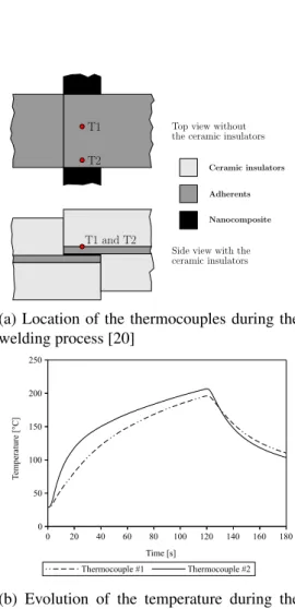
Temperature monitoring during the welding process of a sample with a clamp-ing distance of 1.5 mm showed temperature variations between the centre and the edge of the weld (Fig. 2b). For this specimen, the edge effect resulted in a 10◦C
higher temperature on the top surface at the edge of the adherent, compared to the center. This difference was caused by a clamping distance that was too large. Mod-els will be required to evaluate if the gradients in the weld are larger or smaller than the gradient from the thermocouples located at the top of the adherents. Nonethe-less, the temperature gradient between the center and the edges was not large enough to lead to observable thermal degradation in the fractography results, ei-ther on the edges (from a too large clamping distances) or at the centre of the weld (from a too small clamping distances). It was previously demonstrated that the clamping distance has an important effect on the heat transfer at the edge of the weld [19].
Although the LSS obtained with the nanocomposite heating element are lower than the best results reported in the literature for traditional resistance welding, successful welds were obtained and key optimization parameters were identified for future work. A better understanding and control of those parameters will allow
the production of higher performance joints. The key parameters are
1. the reduced toughness of the nanocomposite due to the addition of a high fraction of MWCNTs,
2. the incomplete polymer melting in the welded zone due to edge effects and 3. the thinner middle section in the welded zone leading to stress concentration
at the edge.
Tensile tests on dogbones made from the nanocomposite showed that the addition of 10% wt. fraction of MWCNTs caused a 40% reduction of the tensile strength compared to virgin PEI. Plasticizers could be used to reduce the negative impact of MWCNTs but the composition of the nanocomposite will need to be balanced so as to still provide a sufficient electrical conductivity. Improving the control of the welding process (clamping distance, time and power density) will reduce the temperature gradients within the welded zone and provide a better wetting over the whole surface of the joint.
3.5. FTIR results
When comparing the FTIR spectra of PEI nanocomposites before and after the welding process, no signs of degradation could be noted (see Supplementary Information). The characteristic peeks for CH3, CH and C O in PEI were left
unchanged by the welding process. 4. Conclusion
Through this work, we have demonstrated that a PEI/MWCNT-based nano-composite heating element could be used for resistance welding of TPCs. An ex-perimental validation using a PEI/MWCNT flat heating element subjected to a DC electric field showed uniform heating. Resistance welding using the PEI/MWCNT heating element in a custom-built welding jig joined CF/PEEK UD panels with
LSS up to 19.6 MPa. Good bonding to the adherents is supported by the cohesive failure mode observed, and no important thermal degradation is measured by FTIR tests. Future work will focus on improving the temperature uniformity in the weld and improving the toughness of the nanocomposite heating element.
5. Acknowledgements
This work was supported by ArianeGroup and CREPEC. The authors also thank Prof. G.S. Patience for the use of the thermal imaging camera and Prof. D. Therriault for access to the microcompounder.
References
[1] Sloan J. I want to say two words to you: “Thermoplastic tapes”. CompositeWorld 2018;:42–9URL:
https://www.compositesworld.com/articles/
i-want-to-say-two-words-to-you-thermoplastic-tapes.
[2] Cogswell FN. Thermoplastic aromatic polymer composites: a study of the structure, processing, and properties of carbon fibre reinforced
polyetheretherketone and related materials. Butterworth-Heinemann; 1992. ISBN 9780750610865.
[3] Ageorges C, Ye L, Hou M. Experimental investigation of the resistance welding of thermoplastic-matrix composites. Part II: optimum processing window and mechanical performance. Compos Sci Technol
2000;60(2000):1191–202. doi:10.1016/S0266-3538(00)00025-7. [4] Houghton WR. Bonding of graphite reinforced thermoplastics using
resistance heating. Ph.D. thesis; Massachusetts Institute of Technology, Department of Mechanical Engineering; 1984.
[5] Eveno EC, Gillespie JW. Resistance Welding of Graphite
Polyetheretherketone Composites: An Experimental Investigation. J Thermoplast Compos Mater 1988;1(4):322–38.
doi:10.1177/089270578800100402.
[6] McKnight SH, Holmes ST, Gillespie JW, Lambing CLT, Marinelli JM. Scaling Issues in Resistance- Welded Thermoplastic Composite Joints. Adv Polym Technol 1997;16(4):279–95.
doi:10.1002/(SICI)1098-2329(199711)16:4<279:: AID-ADV3>3.0.CO;2-S.
[7] Hou M, Yang M, Beehag A, Mai YW, Ye L. Resistance welding of carbon fibre reinforced thermoplastic composite using alternative heating element. Compos Struct 1999;47(1999):667–72.
doi:10.1016/S0263-8223(00)00047-7.
[8] Shi H. Resistance welding of thermoplastic composites: Process and performance. Ph.D. thesis; TU Delft, Delft University of Technology; 2014. [9] Shi H, Villegas IF, Bersee HEN. Strength and failure modes in resistance
welded thermoplastic composite joints: Effect of fibre-matrix adhesion and fibre orientation. Compos Part A Appl Sci Manuf 2013;55:1–10.
doi:10.1016/j.compositesa.2013.08.008.
[10] Dube M, Chazerain A, Hubert P, Yousefpour A, Bersee HE.
Characterization of resistance-welded thermoplastic composite double-lap joints under static and fatigue loading. J Thermoplast Compos Mater 2015;28(6):762–76. doi:10.1177/0892705713490714.
thermoplastic composites skin/stringer joints. Compos Part A Appl Sci Manuf 2007;38:2541–52. doi:10.1016/j.compositesa.2007.07.014. [12] Dube M, Hubert P, Gallet JN, Stavrov D, Bersee HE, Yousefpour A. Metal
mesh heating element size effect in resistance welding of thermoplastic composites. J Compos Mater 2012;46:911–9.
doi:10.1177/0021998311412986.
[13] Dubé M, Hubert P, Yousefpour A, Denault J. Fatigue failure characterisation of resistance-welded thermoplastic composites skin/stringer joints. Int J Fatigue 2009;31(4):719–25. doi:10.1016/j.ijfatigue.2008.03.012. [14] Shi H, Villegas IF, Octeau MA, Bersee HE, Yousefpour A. Continuous
resistance welding of thermoplastic composites: Modelling of heat generation and heat transfer. Compos Part A Appl Sci Manuf 2015;70:16–26. doi:10.1016/j.compositesa.2014.12.007.
[15] Stavrov D, Bersee HEN. Resistance welding of thermoplastic composites-an overview. Compos Part A Appl Sci Manuf 2005;36:39–54.
doi:10.1016/j.compositesa.2004.06.030.
[16] Bauhofer W, Kovacs JZ. A review and analysis of electrical percolation in carbon nanotube polymer composites. Compos Sci Technol
2009;69(10):1486–98. doi:10.1016/j.compscitech.2008.06.018. [17] Crevecoeur G, Groeninckx G. Binary blends of poly(ether ether ketone) and
poly(ether imide). Miscibility, crystallization behavior, and semicrystalline morphology. Macromolecules 1991;24:1190–5.
[18] Smiley AJ, Halbritter A, Cogswell FN, Meakin PJ. Dual polymer bonding of thermoplastic composite structures. Polym Eng Sci 1991;31(7):526–32. doi:10.1002/pen.760310709.
[19] Talbot E, Hubert P, Dube M, Yousefpour A. Optimization of thermoplastic composites resistance welding parameters based on transient heat transfer finite element modeling. J Thermoplast Compos Mater 2013;26(5):699–717. doi:10.1177/0892705711428657.
[20] Brassard D. Data and figures for "Resistance Welding of Thermoplastic Composites with a Nanocomposite Heating Element" 2018;URL: https://figshare.com/account/home{#}/collections/4358771. doi:10.6084/m9.figshare.c.4358771.
Figures • • Force Clamping distance Electrical contacts Adherents Insulator Heating element
(a) Resistance welding main components [20] (b) Ceramic insulators [a], copper elec-trodes [b] and load cell [c]
Top view without the ceramic insulators T1
T2
Side view with the ceramic insulators T1 and T2
Ceramic insulators Adherents Nanocomposite
(a) Location of the thermocouples during the welding process [20] 0 20 40 60 80 100 120 140 160 180 0 50 100 150 200 250 Thermocouple #1 Thermocouple #2 Time [s] Temperature [°C]
(b) Evolution of the temperature during the welding process at 350 kW m−2for 120 s [20] Figure 2: Thermocouples locations and measurements
(a) time= 0 s (b) time= 5 s
(c) time= 10 s (d) time= 20 s
(e) time= 30 s (f) time= 45 s
Figure 3: Thermography of a heating element during the experimental validation under a DC elec-trical field of 800 V m−1[20]
(a) Cohesive failure with a thinner section in the middle [a] and adhesive failure on the sides [b] in a sample welded for 70 s
(b) Mostly cohesive failure in a sample welded for 90 s
Tables
Voltage Electric Maximum Current field surface temperature [V] [V m−1] [◦C] [A] 10 400 44 0.10 15 600 97 0.16 20 800 155 0.23 25 1000 223 0.32 30 1200 >270 N/A
Table 1: Electrical results from the experimental validation, the current at 30 V could not be measured due to melting of the heating element
Clamping distance Values Time
[mm] [s] 60 70 90 120 0 LSS [MPa] 14.5 ± 1.3 Welded area [%] 85 ± 2 1 LSS [MPa] 13.0 ± 4.4 Welded area [%] 83 ± 7 1.5 LSS [MPa] 16.4 ± 7.8 18.6 ± 2.0 15.5 ± 3.8 19.6 ± 3.5 Welded area [%] 57 ± 20 74 ± 10 87 ± 1 78 ± 2 Table 2: LSS and fractography analysis reported as average values ± standard deviation [20]
![Figure 1: Resistance welding jig [20]](https://thumb-eu.123doks.com/thumbv2/123doknet/8182413.274698/18.918.209.715.241.422/figure-resistance-welding-jig.webp)
![Figure 3: Thermography of a heating element during the experimental validation under a DC elec- elec-trical field of 800 V m −1 [20]](https://thumb-eu.123doks.com/thumbv2/123doknet/8182413.274698/20.918.228.687.286.856/figure-thermography-heating-element-experimental-validation-trical-field.webp)
![Figure 4: Fracture surface of specimens welded at 350 kW m −2 with 1.5 mm clamping distance [20]](https://thumb-eu.123doks.com/thumbv2/123doknet/8182413.274698/21.918.192.725.391.546/figure-fracture-surface-specimens-welded-kw-clamping-distance.webp)
![Table 2: LSS and fractography analysis reported as average values ± standard deviation [20]](https://thumb-eu.123doks.com/thumbv2/123doknet/8182413.274698/22.918.195.731.529.703/table-fractography-analysis-reported-average-values-standard-deviation.webp)
