Open Archive TOULOUSE Archive Ouverte (OATAO)
OATAO is an open access repository that collects the work of Toulouse researchers and
makes it freely available over the web where possible.
This is an author-deposited version published in :
http://oatao.univ-toulouse.fr/
Eprints ID : 19270
To link to this article : DOI : 10.1016/j.surfcoat.2017.10.046
URL :
https://doi.org/10.1016/j.surfcoat.2017.10.046
To cite this version :
Lassègue, Pierre and Noé, Laure and
Monthioux, Marc and Caussat, Brigitte Fluidized bed chemical
vapor deposition of copper nanoparticles on multiwalled carbon
nanotubes. (2017) Surface and Coatings Technology, vol. 331. pp.
129-136. ISSN 0257-8972
Any correspondence concerning this service should be sent to the repository
administrator:
[email protected]
Fluidized bed chemical vapor deposition of copper nanoparticles on
multi-walled carbon nanotubes
Pierre Lassègue
a, Laure Noé
b, Marc Monthioux
b, Brigitte Caussat
a,⁎aLaboratoire de Génie Chimique, Université de Toulouse, CNRS, INPT, UPS, Toulouse, France bCentre d'Elaboration des Matériaux et d'Etudes Structurales, CNRS, Toulouse, France
A R T I C L E I N F O
Keywords: CVD Fluidized bed
Multi-walled carbon nanotubes Copper
Nanoparticles Copper acetylacetonate
A B S T R A C T
Multi-walled carbon nanotubes tangled in easy-to-fluidize porous balls have been decorated by pure copper nanoparticles using a pre-industrial fluidized bed chemical vapor deposition process. Copper (II) acetylacetonate Cu(acac)2was used as precursor. The low precursor volatility led to low deposition rates, responsible for a
non-uniformity of the deposit both on the MWCNT balls and from the outer part to the center of the balls. An oxidative pre-treatment of the MWCNTs allowed to increase slightly the deposit weight and uniformity, by creating new nucleation sites on the nanotube surface. It also allowed decreasing the size of Cu nanoparticles by a factor of ten. A decrease of the deposition temperature increased more markedly the deposit weight, by probably favoring the formation of gaseous reactive intermediate species more reactive on the oxidized nano-tube surface. A more efficient precursor delivery system would allow reaching higher deposition rates and much more uniform deposits, making possible an industrial production of metallized carbon nanotubes.
1. Introduction
Multi-walled carbon nanotubes (MWCNTs) are promising nanoma-terials with remarkable physical properties. For example, their thermal conductivity varies between 650 and 3000 W·m− 1·K− 1[1
–2]and their
electrical conductivity reaches 107S·m− 1[3]. These properties make them suitable for various well-reviewed applications [4–6], such as energy storage, catalysis or multi-functional composite materials. But these excellent properties were measured for perfectly-aligned MWCNTs of high purity. The electrical conductivity of industrially produced MWCNTs such as the NC7000® grade (Nanocyl) was mea-sured between 5.4.102and 5.103S·m− 1[3]. These lower values are due to the fact that these MWCNTs are produced under the form of tangles or agglomerates in which each nanotube grows randomly in all three spatial directions with structural defects and in presence of impurities (mainly the catalyst). The thermal conductivity of carpet-like aligned MWCNTs was estimated as close to 180–220 W·m− 1·K− 1[7]. It is then likely that entangled MWCNTs are less conductive. The industrial de-velopment of most of the MWCNT applications previously mentioned needs to increase their thermal or/and electrical conductivities.
This can be achieved by metallizing them, which consists in de-positing a metal under the form of nanoparticles (NPs) on the outer surface of nanotubes. Various processes have been tested, such as electroless deposition [8], sonochemical deposition [9], liquid
impregnation[10], deposition under supercritic fluid[11]or Chemical Vapor Deposition (CVD)[12]. Gas-based processes like CVD generally yield products purer than wet methods. They are single step and gen-erally involve high coating rates[13].
CVD can be adapted to the large scale production of coated MWCNTs provided a good gas-solid contact can be achieved. Gas-solid fluidization consists in flowing a gas upwards through a vertical bed of particles, thus generating an intense gas-solid mixing and then high thermal and mass transfer rates between the gas and the powders[14]. Fluidization can be combined with the CVD technology, giving rise to the Fluidized Bed Chemical Vapor Deposition (FBCVD) process. If the MWCNTs can be fluidized, this technology allows multi-gram scale beds of nanotubes to be uniformly coated with a high conversion rate of the gaseous precursor into solid, high versatility, good homogeneity of products and possibility of continuous operations[15]. This technology is also easy to use and to rescale and requires low equipment costs[15]. Copper (Cu) is one of the best thermal (400 W·m− 1·K− 1) and electrical (5.9.106S·m− 1) metallic conductors. The deposition of copper on MWCNTs has already been performed by laser ablation[16], electroless plating[17]and MOCVD[18], but only at the milligram scale. The sole MOCVD precursor tested has been Cu(hfac)(tmvs) (tmvs = trimethylvinylsilyl) under a hydrogen‑argon mixture, at tem-peratures between 120 and 200 °C. MWCNTs were first plasma-acti-vated (H2, N2or Ar), then suspended in ethanol and dropped onto a Si
⁎Corresponding author.
substrate. They were then annealed at 400 °C under vacuum and then plasma-activated again prior to deposition. Copper was deposited under the form of nanoparticles whose size and density depended on the pre-treatment and deposition conditions. Yet this previous work was rea-sonably successful, the related route cannot be up-scaled because of the expensiveness of the Cu(hfac)(tmvs) molecule and of the many steps involved. Among all the existing CVD copper precursors [19–21],
copper (II) acetylacetonate (Cu(acac)2) does not contain heteroatoms such as N, F or Si, as opposed to [Cu(sBu-amd)]2, Cu(hfac)2or Cu(hfac) (vtms) precursors, respectively[21], which could pollute the deposit. Furthermore, it does not produce any toxic decomposition products, e.g. CuCl2[21], and it is one of the rare copper precursors commercially available at reasonable price. It was successfully used to deposit copper thin films on planar substrates such as borosilicate glass[22], silicon
[23,24], Kapton polymer[25]and metals (Al, Ni and Pd)[26]. At at-mospheric pressure, pure copper was obtained between 220 and 400 °C under pure hydrogen or using N2/H2or Ar/H2mixtures with H2 con-centrations higher than 50 vol% [22,23,26]. To the best of our knowledge, Cu(acac)2has never been used to deposit copper on na-notubes.
A limitation to metal deposition on the surface of MWCNTs concerns their chemical inertness[13]. Indeed, carbon nanotube walls are rather unreactive due to the seamless arrangement of hexagonal carbon rings without any dangling bond [23]. Experimental observations have clearly shown that the intrinsic surface defects play an important role in the adsorption of atoms on MWCNTs. This is why a surface activation in the form of functionalization or creation of defects at the carbon na-notube surface is essential to achieve high coating density [12,13]. Indeed, the deposited weight of metal is higher and the NPs are smaller and better dispersed along the MWCNT walls [27–31]. The most
common method at the lab-scale is to oxidize carbon nanotubes by exposure to concentrated acidic liquids, but the liquid wastes and the noxious gases generated by this wet oxidation method, as well as the necessity to repeatedly wash and dry the CNTs, are not suited for in-dustrial use[32–35]. Gas phase oxidation is much cleaner, it only in-volves one step and can be operated at large scale using appropriate processes [35–36]. We have developed an original pre-industrial oxi-dation process able to treat 100 g of MWCNTS per run, using a fluidized bed reactor fed with ozone-containing gas mixtures [37]. Oxygen-containing chemical groups were uniformly grafted on the nanotube surface and a moderate etching of the MWCNT walls was observed, forming nano-pits on the outer nanotube walls. For the present work, raw and oxidized MWCNTs were used.
This article describes the copper deposition from Cu(acac)2on 100 g of MWCNTs in a pre-industrial fluidized bed chemical vapor deposition (FBCVD) reactor. The influences of the MWCNT pre-oxidation and of the deposition temperature were analyzed. The process behavior was studied in terms of fluidized bed pressure drop and temperature pro-files. The weight, chemical composition, morphology, uniformity and crystalline state of the deposits were analyzed in details.
2. Experimental 2.1. The FBCVD reactor
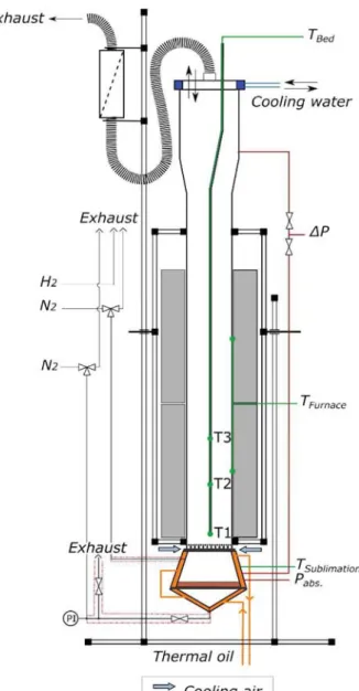
The experimental FBCVD set-up is presented inFig. 1. It consists in a vertical stainless steel column (8.3 cm internal diameter and 1 m height). At the bottom of the column, a perforated stainless steel plate (called the distributor) provided a homogeneous gas distribution. At the exhaust of the reactor, a HEPA13 filtration cartridge allowed collecting the elutriated particles. The top of the column was water-cooled to avoid any seal degradation. The reactor was externally heated by a two-zone external furnace and the wall temperature was monitored by two K-type thermocouples. Three other K-type thermocouples were placed into a 6 mm diameter tube along the vertical axis of the reactor (T1 at 6 cm above the distributor, T2 at 12 cm and T3 at 18 cm). An oil-heated
sublimator containing the copper organometallic precursor was directly connected to the bottom of the reactor. The distributor was cooled by air to avoid any premature decomposition of the precursor. A differ-ential pressure sensor (Unik5000– Druck Ltd.) measured the pressure drop across the bed. An absolute pressure sensor (PR21– Keller) al-lowed monitoring the total pressure below the distributor, in order to detect any plugging. The temperatures and pressures were recorded in real time by a Minitrend®QX (Honeywell) device and treated by the TrendServer Pro software (6.4.41 version – Honeywell). All experi-ments were performed at atmospheric pressure. Gas flows (N2and H2– Air Liquide) were regulated by mass flow controllers (FC-7700 type– Aera). Gas lines were heated by heating ribbons to avoid any con-densation of the precursor before its entrance into the reactor. 2.2. Chemicals and substrates
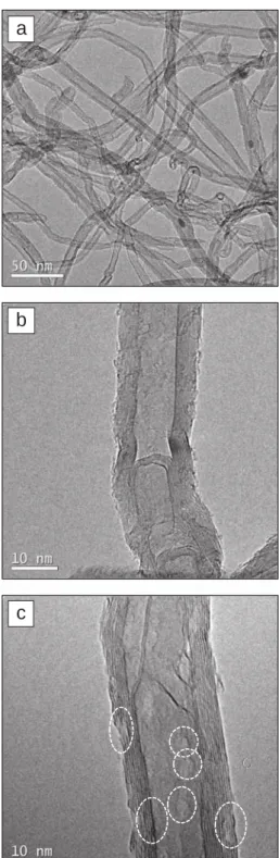
Copper (II) acetylacetonate (CuC10H14O4or Cu(acac)2, 97%– Sigma Aldrich) was used as received. MWCNTs Graphistrength® C100 – Arkema was the powder substrate. As illustrated inFig. 2a and b, they are entangled in coarsely spherical balls (Sauter diameter of 340 μm, specific surface area of 214 m2·g− 1) of nanotubes (7 to 20 nm in ex-ternal diameter and wall number between 5 and 15), which present
Fig. 1. Scheme of the experimental set-up. P. Lassègue et al.
some intrinsic structural defects (Fig. 3a and b). This powder was used as received, without any purification step. As they are industrially produced, they present varying surface morphologies from very smooth to very rough, with sometimes the presence of protrusions (Fig. 2a). Their intrinsic iron content determined by ICP-MS is of 1.35 ± 0.06 wt %. Their untapped density is equal to 90 kg·m− 3. After oxidation in fluidized bed, pits are present along the MWCNT surface, as it can be seen inFig. 3c. These nano-pits are observed from the outer part to the center of balls, indicating that the oxidation process is uniform on the whole MWCNT surface. Similarly, XPS and FT-IR measurements have shown that oxygen-containing groups are grafted uniformly on the nanotube surface [37]. However, as detailed elsewhere [34], the amount of structural defects created by the fluidized bed ozone pre-treatment is low and the amount of grafted oxygen can easily be tuned by the operating conditions. As found by other authors[38,39], these MWCNT balls are easy to fluidize. Their minimum fluidization velocity (Umf) was measured under nitrogen at room temperature as equal to 1.3 cm·s− 1.
2.3. Operating conditions
The operating conditions tested are listed in Table 1. For all the experiments, the initial mass of raw MWCNTs bed was equal to 100 g, leading to an initial fixed bed height of 17.5 cm. The oxidation of the MWCNTs by fluidization led to a slight loss of mass due to elutriation and to carbon etching, which respectively occurred during the fluidi-zation and the oxidation of the powder. Consequently, the initial fixed
c
b
a
Fig. 3. FEG-SEM and HRTEM views of the (a–b) raw and (c) oxidized MWCNTs – circles show the defects created by the oxidation.
Table 1
Operating FBCVD conditions tested.
Run Cu1 Cu2 Cu3
Oxidative pretreatment No Yes Yes Initial bed height (g) 100 97.8 97.1 Deposition temperature (°C) 280 280 250 Volumic composition of the gas phase (%) H2= 61.7
N2= 38.3 H2= 61.7 N2= 38.3 H2= 65.7 N2= 34.2
1 mm
a
b
1 µm
bed height of oxidized MWCNTs was about 17 cm. The sublimation temperature was of 210 °C, leading to an inlet molar fraction of Cu (acac)2 close to 0.3%. This value was estimated assuming that the sublimator operated at the thermodynamic equilibrium using the vapor pressure equation of Siddiqi et al.[40]. The deposition duration was set at 8 h. This quite long duration was chosen because of the low volatility of the precursor, as it will be explained below.
2.4. Characterization
Observations of the MWCNTs before and after experiments were performed on a JSM-7100F (Jeol) field emission gun scanning electron microscope (FEG-SEM) associated to an energy dispersive X-ray (EDX) detector (X-MAXN
– Oxford Instrument). A CM30 (Philips) high re-solution transmission electron microscope (HRTEM) was also used, equipped with a LaB6gun operating at 150 kV to minimize damaging irradiation effects. For some FEG-SEM observations and EDX analyses, some balls were half-cut using a scalpel. The nature and crystal state of the deposit were determined by X-ray diffraction (XRD) using a D8-2 (Drucker) with a monochromatic Kα copper (Cu) source (λ = 1.5418 Å). Electron-ionization mass-spectrometry was carried-out on a GCT Premier (Water) to study the decomposition mechanism of Cu (acac)2. Finally, an inductively coupled plasma mass spectrometer (ICP-MS) was used to determine the copper content.
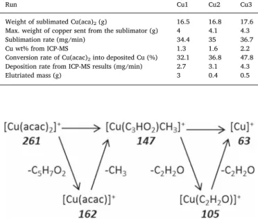
Table 2
Results obtained after FBCVD experiments.
Run Cu1 Cu2 Cu3
Weight of sublimated Cu(aca)2(g) 16.5 16.8 17.6 Max. weight of copper sent from the sublimator (g) 4 4.1 4.3 Sublimation rate (mg/min) 34.4 35 36.7
Cu wt% from ICP-MS 1.3 1.6 2.2
Conversion rate of Cu(acac)2into deposited Cu (%) 32.1 36.8 47.8 Deposition rate from ICP-MS results (mg/min) 2.7 3.1 4.3
Elutriated mass (g) 3 0.4 0.5
Fig. 4. Proposed decomposition mechanism of Cu(acac)2– the italic numbers correspond to the mass-to-charge (m/z) ratio value of the intermediated structures.
Fig. 5. XRD spectra of MWCNTs before and after deposition.
1 mm
Cu
a
b
Fig. 6. (a) FEG-SEM view of the MWCNTs balls after run Cu1; (b) corresponding Cu EDX signal. P. Lassègue et al.
3. Results and discussion 3.1. Process behavior
The results obtained after copper deposition are detailed inTable 2. First, the deposit weight was low for all the runs since it did not exceed 2 g on 100 g of MWCNTs. This low weight is partly due to the low volatility of Cu(acac)2, since only 4.3 g maximum of copper present in the vaporized precursor molecules were sent from the sublimator to the reactor. This is also related to the reactivity of the precursor on the surface of the MWCNTs, which is quite low since the maximum value of the conversion rate of Cu(acac)2 into deposit is of 48%. As a con-sequence, the deposition rate did not exceed 4.3 mg/min for these ex-periments.
This certainly explains the fact that the presence of Cu(acac)2into the fluidized bed did not disturb the bed thermal profile and pressure drop. Indeed, the fluidized bed was isothermal all along the deposition duration and the bed pressure drop remained equal to the theoretical bed pressure drop (i.e. the bed weight per unit column section area). This means that the bed was conveniently fluidized all along the deposit duration.
ICP-MS (Table 2) and XRD results (detailed inSection 3.2) indicate that for all runs, the deposit is made of pure copper.Table 2also shows that the MWCNT oxidation allowed increasing the weight percentage of deposited Cu from 1.3 to 1.6% (runs Cu1 and Cu2), and logically the Cu (acac)2conversion and deposition rates increased too. This means that the oxidative pretreatment has created new nucleation sites, constituted of structural defects (nano-pits) and grafted oxygen-containing func-tions. However the effect is moderate.
The decrease of temperature from 280 to 250 °C on oxidized MWCNTs is more efficient since the weight percentage of deposited Cu increases from 1.6 to 2.2% and the deposition rate from 2.7 to 4.3 mg/ min (runs Cu2 and Cu3). For this range of temperature, no effect on the deposition rate was observed when depositing Cu from Cu(acac)2under hydrogen on planar glass substrates by Atmospheric Pressure CVD[13]. Since the mechanisms of Cu(acac)2decomposition are poorly known, we have performed an analysis by mass spectrometry of the precursor decomposition (results given in the supplementary material). Fig. 4
details the decomposition pathways which have been deduced. It seems that they are quite complex since some intermediate species could be formed by the successive loss of acetylacetonate, methyl and C2H2O ligands, before pure Cu could be obtained. To explain our results on MWCNTs, it is then possible that higher temperatures result in a more complete gas phase thermal decomposition of Cu(acac)2, giving rise to less reactive species than at 250 °C.
The comparison of the weight of sublimated Cu(acac)2 from the three experiments indicates that the sublimator generated quite re-producible precursor flow rates close to 35.4 mg·min− 1. Moreover,
these flow rates are close to the value calculated from the vapor pres-sure equation[37], meaning that the sublimator placed just under the fluidized bed has been well designed since it operates in conditions close to the thermodynamic equilibrium.
As detailed inTable 2, the elutriation remains quite low, close to 6 mg/min for the raw MWCNTs and of 0.8 mg/min for the oxidized MWCNTs. This lower value can be explained by the fact that the oxi-dized MWCNTs have already been fluioxi-dized and then the remaining fines subjected to elutriation are less numerous.
Fig. 7. EDX line profiles of the element Cu performed on half-cut MWCNTs balls after (a) run Cu1 and (b) run Cu2.
1 µm
a
b
1 µm
Fig. 8. (a) FEG-SEM view of the surface of a ball; (b) FEG-SEM view of the center of a half-cut ball.
3.2. XRD results
MWCNTs were analyzed by XRD before and after experiments, as detailed in Fig. 5. Raw Graphistrength®C100 MWCNTs exhibit four characteristic peaks. 002C and 004C peaks, at 2θ = 25.8° and 51.7° respectively, correspond to the first and second order diffraction spots related to the inter-graphene stacking distance[41]. 10Cand 11Cpeaks, at 2θ = 42.7° and 78.2° respectively, correspond to the in-plane peri-odicities of graphenes when stacked turbostratically [41,42]. Three other signals are visible at 2θ = 37.3°, 44.5° and 48.5–49° (*symbol on
Fig. 5). They could be related to iron carbide (Fe3C) since iron NPs should be saturated with carbon atoms as they act as the catalyst for the MWCNT growth [43]. After deposition, three new peaks appear at 2θ = 43.3°, 50.4° and 74.0° for all the runs. These peaks represent the 111, 200 and 220 reflections of pure copper[22,24,25]. The intensity of these peaks is relatively low due to the low amount of copper measured by ICP-MS. No oxide was detected since cuprous oxide (Cu2O) and cupric oxide (CuO) should have intense peaks at 2θ = 36.1° and 39° respectively (111 reflection) [44,45]. So, the deposit on MWCNTs is polycrystalline metallic copper.
3.3. FEG-SEM and HRTEM results
Fig. 6show the FEG-SEM views and EDX cartographies of run Cu1. According to the views of the whole analyzed population, some MWCNT balls seem to be coated by a higher amount of metal than
others, as shown by the EDX cartography inFig. 6b. As previously ex-plained, MWCNTs are entangled in coarsely spherical balls and present various surface morphologies and micro and nanoscale structural de-fects. The copper deposition seems to preferentially occur on the biggest balls and on those presenting a rough surface morphology. It must be noted that this is the first time according to our knowledge, that a non-uniform deposition is observed on MWCNT balls using the FBCVD process. In previous works of our group, silicon (Si)[38], tin dioxide (SnO2)[46]and iron carbide (Fe3C)[47]were uniformly deposited on all the MWCNT balls in the fluidized bed under the form of NPs, but the deposit weights were significantly higher than in this study (at least 10 g on 100 g of MWCNTs). A possible explanation is that the biggest balls are more present at the bottom of the bed close to the distributor and are then more exposed to the fresh precursor vapor. It is also possible that the rough balls present more structural defects, therefore exhibiting more nucleation sites for copper.
Cu line profiles were performed on three half-cut MWCNT balls having a strong Cu EDX signal. One representative example is given in
Fig. 7a. Copper is mainly present in the first 20–40 μm in depth into the balls. Then a lower concentration is present till 200 μm in depth. The center of the balls seems to be free of Cu. These results clearly reveal that the diffusion of the gaseous species in the ball porosity is the limiting step of the process. This is certainly due to the low inlet molar fraction of the Cu(acac)2precursor and to its complex decomposition mechanism.
Fig. 8a shows a micrograph of the surface of a MWCNT ball where
100 nm
c
d
1 µm 100 nme
f
100 nma
b
1 mmFig. 9. (a) FEG-SEM view and (b) corresponding EDX signal of the MWCNT balls after run Cu2 and FEG-SEM view of the MWCNT surface (c, d) after run Cu2 and (e, f) run Cu3.
copper was strongly present. Copper was deposited under the form of NPs uniformly dispersed. The size of the NPs – between 100 and 500 nm– is in agreement with the results obtained for electrodeposited Cu NPs from Cu(acac)2[48]. At the center of the ball (Fig. 8b), the NPs were smaller, about 50 to 150 nm, and more scattered. Their distribu-tion in the porous medium is quite uniform. According to the low binding energy between the graphitic external surface of a carbon na-notube and copper (0.7 eV)[48], the copper deposition seems to be difficult without an oxidative pretreatment of the MWCNTs making them more chemically reactive.
According toFig. 9a and b, the FEG-SEM-EDX analyses performed on the whole population of balls after oxidation (runs Cu2) show that the deposit is still non uniform on the balls, but with a more intense Cu signal compared to run Cu1. EDX line profiles performed on half-cut balls (Fig. 9b, representative of both runs Cu2 and Cu3) indicate that copper was still mainly present at the surface of the balls but a weak signal was detected inside the analyzed balls. This confirms that the oxidative pretreatment of the MWCNTs favors the deposition of copper by creating new nucleation sites.
Fig. 9c–f present FEG-SEM micrographs of the ball surface after runs Cu2 and Cu3. As it can be seen, MWCNTs are entirely coated by Cu NPs. These views demonstrate that copper clearly nucleated on the MWCNT surface. The diameter of these NPs is about 10 to 50 nm for run Cu2, which is much smaller than for run Cu1. So, the oxidation of MWCNTs allows increasing the number of nucleation sites and lowering the NP size. This result is in accordance with those obtained after CNT oxida-tion for Cu electrodeposioxida-tion[48], as well as for other metals like Pd
[27]or Pt[28]deposited by wet methods. Furthermore, by comparing
Fig. 9d and f, the decrease of the deposition temperature leads to a small decrease of the NP size, equal to 10 to 20 nm for run Cu3.
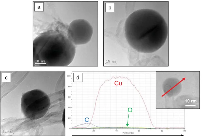
The HRTEM views ofFig. 10a–c are typical micrographs showing that the Cu NPs often deposit onto MWCNTs structural defects, as it was
observed for Si deposition by FBCVD[38]. Some EDX line profiles were performed on few NPs. One representative example is given inFig. 10d. NPs are constituted of pure copper, which is in agreement with the XRD results. The oxygen profile shows that no oxide was detected, even after several weeks of storage. The carbon signal comes from the NP en-vironment, i.e. the MWCNT. This means that such stable Cu NPs could be of interest for catalysis or conductive nano-fillers applications. 4. Conclusion
For the first time, pure, polycrystalline copper nanoparticles were deposited onto MWCNTs by Fluidized Bed Chemical Vapor Deposition from copper acetylacetonate, a low-cost copper precursor. The gas phase route proposed is single step, which is unprecedented, and allows large amounts of MWCNTs, 100 g per run, to be treated, which is an-other novelty regarding the state of the art about carbon nanotube metallization. Furthermore, this process is itself up-scalable.
The low volatility of the precursor led to a small inlet molar fraction of Cu(acac)2and then to low deposition rates, responsible for a non-uniformity of the deposit both on the MWCNT balls and from the outer part to the center of the balls. The oxidative pre-treatment of the MWCNTs allowed to increase slightly the deposit weight and uni-formity, by creating new nucleation sites on the nanotube surface. It also allowed decreasing the size of Cu nanoparticles by a factor of ten (from 100-500 nm to 10–50 nm). The decrease of temperature from 280 to 250 °C increased more markedly the deposit weight, by probably favoring the formation of intermediate species more reactive on the oxidized nanotube surface.
This work demonstrates that the FBCVD process can be used at large scale to metallize or more largely decorate industrial MWCNTs tangled in easy-to-fluidize balls in one step, without any liquid waste at mod-erate cost. To overcome the limitation of the low precursor volatility, a
Cu
C
O
c
10 nm
d
a
b
Fig. 10. (a–c) HRTEM views of Cu nanoparticles deposited on MWCNTs after run Cu3 and (d) EDX line profiles of the C, O and Cu elements corresponding to the Cu nanoparticle of the insert.
more efficient delivery system like Direct Liquid Injection (DLI) could be used[49], in order to work with much higher inlet precursor molar fractions. Thanks to its versatility, the FBCVD process allows depositing various metals or metalloids on MWCNTs or on other porous or non-porous powders, this opening the way for the industrial production of innovative multi-functional materials in the fields of catalysis, Li-ion battery, and composite materials.
Acknowledgements
This work was supported by the Midi-Pyrénées Region and by the French WASPE (F1305021M) (Weight Saving for Aerospace Packaging Equipments) FUI project. The authors thank M. Molinier, J. Compain and E. Prévot from LGC for technical help, Antellis for performing the ICP-MS analyses and Arkema for providing the multi-walled carbon nanotubes.
Appendix A. Supplementary data
Supplementary data to this article can be found online athttps:// doi.org/10.1016/j.surfcoat.2017.10.046.
References
[1] P. Kim, L. Shi, A. Majumdar, P.L. McEuen, Thermal transport measurements of individual multi-walled nanotubes, Phys. Rev. Lett. 87 (2001) (215502-1–215502-4).
[2] T.Y. Choi, D. Poulikakos, J. Tharian, U. Sennhauser, Measurement of thermal conductivity of individual multi-walled carbon nanotubes by the 3-ω method, Appl. Phys. Lett. 87 (2005) (013108-1–013108-3).
[3] B. Marinho, M. Ghislandi, E. Tkalya, C.E. Koning, G. de With, Electrical con-ductivity of compacts of graphene, multi-wall carbon nanotubes, carbon black, and graphite powder, Powder Technol. 221 (2012) 351–358.
[4] R.H. Baughman, A.A. Zakhidov, W.A. de Heer, Carbon nanotubes - the route toward applications, Science 297 (2002) 787–792.
[5] M.F.L. de Volder, S.H. Tawfick, R.H. Baughman, A.J. Hart, Carbon nanotubes: present and future commercial applications, Science 339 (2012) 535–539. [6] S. Abdalla, F. Al-Marzouki, A.A. Al-Ghamdi, A. Abdel-Daiem, Different technical
applications of carbon nanotubes, Nanoscale Res. Lett. 10 (2015) 358–368. [7] M. Gaillard, H. Mbitsi, A. Petit, E. Amin-Chalhoub, C. Boulmer-Leborgne,
N. Semmar, E. Million, J. Mathias, S. Kouassi, Electrical and thermal character-ization of carbon nanotube films, J. Vac. Sci. Technol. B 29 (2011) 041805-1. [8] F. Wang, S. Arai, M. Endo, Metallization of multi-walled carbon nanotubes with
copper by an electroless deposition process, Electrochem. Commun. 6 (2004) 1042–1044.
[9] M.V. Landau, S.V. Savilov, M.N. Kirikova, N.B. Cherkasov, A.S. Ivanov, V.V. Lunin, Y. Koltypin, A. Gedanken, Decoration of multiwall carbon nanotubes with nickel nanoparticles: effect of deposition strategy on metal dispersion and performance in the hydrogenation of p-chloroacetophenone, Mendeleev Communications 21 (2011) 125–128.
[10] A. Martínez-Ruiz, G. Alonso-Nuñez, New synthesis of Cu2O and Cu nanoparticles on multi-wall carbon nanotubes, Mater. Res. Bull. 43 (2008) 1492–1496.
[11] E. Garrido, Fonctionnalisation De Nanotubes De Carbone Pour Leur Incorporation Dans Des Matrices Métalliques (Ph.D Thesis), I Université Sciences et Technologies, Bordeaux, 2010.
[12] M.M. Feng, R.J. Puddephatt, Chemical vapor deposition of nickel-group metals on multiwall carbon nanotubes, Can. J. Chem. 85 (2007) 645–650.
[13] R.R. Bacsa, Ph.P Serp, Decorated (coated) carbon nanotubes, in: M. Monthioux (Ed.), Carbon Meta-Nanotubes, Synthesis, Properties and Applications, Wiley, 2012, pp. 163–207.
[14] D. Kunii, O. Levenspiel, Fluidization Engineering, 2nd edition, (1991). [15] C. Vahlas, B. Caussat, Ph. Serp, G.N. Angelopoulos, Principles and applications of
CVD powder technology, Mater. Sci. Eng. R. Rep. 53 (2006) 1–72.
[16] A. Koshio, M. Shiraishi, Y. Kobayashi, M. Ishihara, Y. Koga, S. Bandow, S. Iijima, F. Kokai, Modification of carbon nanotubes by laser ablation of copper, Chem. Phys. Lett. 396 (2004) 410–414.
[17] C. Xu, G. Wu, Z. Liu, D.i Wu, T.T. Meek, Q. Han, Preparation of copper nano-particles on carbon nanotubes by electroless plating method, Mater. Res. Bull. 39 (2004) 1499–1505.
[18] C. Täschner, K. Biedermann, A. Leonhardt, B. Büchner, T. Gemming, K. Wetzig, Decorating of multi-walled carbon nanotubes by copper particles using MOCVD, Electrochem. Soc. Proc. 9 (2005) 396–402.
[19] P. Doppelt, Why is coordination chemistry stretching the limits of micro-electronics technology? Coord. Chem. Rev. 178 (1998) 1785–1809.
[20] J. Rickerby, J.H.G. Steinke, Current trends in patterning with copper, Chem. Rev. 102 (2002) 1525–1550.
[21]P.G. Gordon, A. Kurek, S.T. Barry, Trends in copper precursor development for CVD and ALD applications, ECS J. Solid State Sci. Technol. 4 (2015) N3188–N3197. [22]T. Maruyama, T. Shirai, Copper thin films prepared by chemical vapour deposition
from copper (II) acetylacetonate, J. Mater. Sci. 30 (1995) 5551–5553. [23]Y. Pauleau, A.Y. Fasasi, Kinetics of sublimation of copper(II) acetylacetonate
complex used for chemical vapor deposition of copper films, Chem. Mater. 3 (1991) 45–50.
[24]H.A. Marzouk, J.S. Kim, P.J. Reucroft, R.J. Jacob, J.D. Robertson, C. Eloi, Evaluation of copper Chemical-Vapor-Deposition films on glass and Si(100) sub-strates, Appl. Phys. A 58 (1994) 607–613.
[25]H.A. Marzouk, J.Y. Kim, J.S. Kim, P.J. Reucroft, R.J. Jacob, J.D. Robertson, C. Eloi, Non-selective copper film growth on Kapton (polyimide) by MOCVD, Thin Solid Films 249 (1994) 22–27.
[26]H. Miura, K. Oki, H. Ochiai, H. Higuchi, M. Terasaka, T. Matsuda, Preparation of Cu thin films by the decomposition of copper acetylacetonate on catalytically active substrate surfaces, Bull. Chem. Soc. Jpn. 65 (1992) 892–896.
[27]R.M. Lago, S.C. Tsang, K.L. Lu, Y.K. Chen, M.L.H. Green, Filling carbon nanotubes with small palladium metal crystallites: the effect of surface acid groups, J. Chem. Soc. Chem. Commun. 13 (1995) 1355–1356.
[28]Y. Li, F.P. Hu, X. Wang, P.K. Shen, Anchoring metal nanoparticles on hydrofluoric acid treated multi-walled carbon nanotubes as stable electrocatalysts, Electrochem. Commun. 10 (2008) 1101–1104.
[29]C. Bittencourt, A. Felten, B. Douhard, J.F. Colomer, G. Van Tendeloo, W. Drube, J. Ghijsen, J.J. Pireaux, Metallic nanoparticles on plasma treated carbon nanotubes: Nano2hybrids, Surf. Sci. 601 (2007) 2800–2804.
[30]A. Felten, J. Ghijsen, J.J. Pireaux, W. Drube, R.L. Johnson, D. Liang, M. Hecq, G. Van Tendeloo, C. Bittencourt, Electronic structure of Pd nanoparticles on carbon nanotubes, Micron 40 (2009) 74–79.
[31]I. Suarez-Martinez, C.P. Ewels, X. Ke, G. Van Tendeloo, C. Thiess, W. Drube, A. Felten, J.J. Pireaux, J. Ghijsen, C. Bittencourt, Study of the interface between rhodium and carbon nanotubes, ACS Nano 4 (2010) 1680–1686.
[32]V. Datsyuk, M. Kalyva, K. Papagelis, J. Parthenios, D. Tasis, A. Siokou, I. Kallitsis, C. Galiotis, Chemical oxidation of multi-walled carbon nanotubes, Carbon 46 (2008) 833–840.
[33]K. Peng, L.Q. Liu, H. Li, H. Meyer, Z. Zhang, Room temperature functionalization of carbon nanotubes using an ozone/water vapor mixture, Carbon 49 (2011) 70–76. [34]B. Scheibe, E. Borowiak-Palen, R.J. Kalenczuk, Oxidation and reduction of
multi-walled carbon nanotubes - preparation and characterization, Mater. Charact. 61 (2010) 185–191.
[35]D.C. Vennerberg, R.L. Quirino, Y. Jang, M.R. Kessler, Oxidation behavior of multi-walled carbon nanotubes fluidized with ozone, ACS Appl. Mater. Interfaces 6 (2014) 1835–1842.
[36]H. Xia, Y. Zhang, C. Chen, W. Wu, K. Yao, J. Zhang, Ozone-mediated functionali-zation of multi-walled carbon nanotubes and their activities for oxygen reduction reaction, J. Mater. Sci. Technol. 32 (2016) 533–538.
[37]P. Lassègue, Oxydation En Lit Fluidisé Et Dépôt De Métaux Par Cvd En Lit Fluidisé Sur Nanotubes De Carbone Multi-Parois– Application À L'industrie Aéronautique (PhD Thesis), Institut National Polytechnique de Toulouse, 2016.
[38]N. Coppey, L. Noé, M. Monthioux, B. Caussat, Decorated carbon nanotubes by si-licon deposition in fluidized bed for Li-ion battery anodes, Chem. Eng. Res. Des. 91 (2013) 2491–2496.
[39]S.W. Jeong, J.H. Lee, J. Kim, D.H. Lee, Fluidization behaviors of different types of multi-walled carbon nanotubes in gas–solid fluidized beds, J. Ind. Eng. Chem. 35 (2016) 217–223.
[40]M.A. Siddiqi, R.A. Siddiqui, B. Atakan, Thermal stability, sublimation pressures, and diffusion coefficients of anthracene, pyrene, and some metal β-diketonates, J. Chem. Eng. Data 54 (2009) 2795–2802.
[41]G.W. Lee, J. Kim, J. Yoon, J.S. Bae, B.C. Shin, I.S. Kim, W. Oh, M. Ree, Structural characterization of carboxylated multi-walled carbon nanotubes, Thin Solid Films 516 (2008) 5781–5784.
[42]A. Cao, C. Xu, J. Liang, D. Wu, B. Wei, X-ray diffraction characterization on the alignment degree of carbon nanotubes, Chem. Phys. Lett. 344 (2001) 13–17. [43]R. Philippe, B. Caussat, A. Falqui, Y. Kihn, P. Kalck, S. Bordère, D. Plée, P. Gaillard,
D. Bernard, P. Serp, An original growth mode of MWCNTs on alumina supported iron catalysts, J. Catal. 263 (2009) 345–358.
[44]M. Salavati-Niasari, F. Davar, Synthesis of copper and copper(I) oxide nanoparticles by thermal decomposition of a new precursor, Mater. Lett. 63 (2009) 441–443. [45]R. Etefagh, E. Azhir, N. Shahtahmasebi, Synthesis of CuO nanoparticles and
fabri-cation of nanostructural layer biosensors for detecting Aspergillus niger fungi, Sci. Iran. 20 (2013) 1055–1058.
[46]P. Lassègue, N. Coppey, L. Noé, M. Monthioux, B. Caussat, Decoration of carbon nanotubes by semiconducting or metallic nanoparticles using fluidized bed che-mical vapor deposition, KONA Powder Part. J. 33 (2016) 322–332.
[47]P. Lassègue, L. Noé, M. Monthioux, B. Caussat, Iron deposition on multi-walled carbon nanotubes by fluidized bed MOCVD for aeronautic applications, Phys. Status Solidi C 12 (2015) 861–868.
[48]E. Durgun, S. Dag, S. Ciraci, O. Gülseren, Energetics and electronic structures of individual atoms adsorbed on carbon nanotubes, J. Phys. Chem. B 108 (2004) 575–582.
[49]P.L. Etcheparre, L. Baggetto, H. Vergnes, D. Samelor, D. Sadowski, B. Caussat, C. Vahlas, Amorphous alumina barrier coatings on glass: MOCVD process and hy-drothermal aging, Adv. Mater. Interface 3 (2016) 1–9

![Fig. 5 ). They could be related to iron carbide (Fe 3 C) since iron NPs should be saturated with carbon atoms as they act as the catalyst for the MWCNT growth [43]](https://thumb-eu.123doks.com/thumbv2/123doknet/3059633.86334/7.892.59.569.563.1138/related-carbide-saturated-carbon-atoms-catalyst-mwcnt-growth.webp)