To cite this version :
Saqui-Sannes, Pierre de and Apvrille, Ludovic
Making Modeling Assumptions an Explicit Part of Real-Time
Systems Models
.
In: Proceedings of the 8th European Congress Embedded real time
software and systems ERTS2 2016, 27 January 2016 - 29 January
2016 (Toulouse, France).
O
pen
A
rchive
T
OULOUSE
A
rchive
O
uverte (
OATAO
)
OATAO is an open access repository that collects the work of Toulouse researchers and
makes it freely available over the web where possible.
This is an author-deposited version published in :
http://oatao.univ-toulouse.fr/
Eprints ID : 14631
Any correspondance concerning this service should be sent to the repository
Making Modeling Assumptions an Explicit Part
of Real-Time Systems Models
Pierre de Saqui-Sannes1and Ludovic Apvrille2
1
Institut Sup´erieur de l’A´eronautique et de l’Espace (ISAE-SUPAERO), Universit´e de Toulouse, 31055 Toulouse Cedex 04, France
2
LTCI, CNRS, T´el´ecom ParisTech, Universit´e Paris-Saclay, Biot, France [email protected]
Keywords. Model-Based System Engineering, Modeling Assumption, SysML.
1
Introduction
Facing parallelism, determinism, and timelines problems, a real-time system de-signer attempts to master design complexity by making abstractions and creating models. For instance, somebody modeling a pressure controller may assume the pressure sensor and the alarm never fail. Beyond this simple example, it clearly turns that a real-time system model is valid for a precise set of assumptions. An explicit knowledge of these assumptions is an asset to make the model easy to share. Moreover, this knowledge contributes to remove ambiguities.
Surprisingly, little work has been published on the necessity to make modeling assumptions a full part of a system model. Conversely, this paper advocates for an explicit inclusion of modeling assumptions into the system model and dis-cusses solutions in the context of the OMG’s System Modeling Language (SysML [1]). The solution illustrated on the definition of so-called ”Modeling Assump-tions Diagrams” is not restricted to SysML and may be reused, e.g., for UML or AADL. An important issue discussed by the paper is the versioning one. Indeed, our approach proposes to explicitly set or release modeling assumptions along an incremental modeling process.
The paper is organized as follows. Section 2 sketches a process that explicitly include modeling assumptions definition. Section 3 introduces Modeling Assump-tion Diagrams (MADs fort short). The TTool tool [4] adds MADs to SysML. Section 4 discusses a case study: a UAV platform for autonomous navigation across buildings. Section 5 surveys related work. Section 6 concludes the paper.
2
Process
The SysML standard defines a notation, not a method. We thus need to associate a process with the SysML language. The one described below is supported by the free (i.e., ”libre”) TTool tool [4]. The latter supports several UML/SysML profiles. The SysML framework considered in this paper is called AVATAR [2]. TTool supports the Modeling Assumption Diagram presented in this paper as well as the whole AVATAR process described below.
1. Assumptions. One or several Modeling Assumption Diagrams captures as-sumptions linked with the system under design and its environment. 2. Requirement capture. A Requirement Diagram hierarchically organizes safety
and security requirements with explicit notion of refinement and derivation of technical requirements from logical ones.
3. Analysis. One or several Use-Case Diagrams identify the main functions and services offered by the system. The use cases are documented by scenarios (sequence diagrams) and flow charts (activity diagrams).
4. Design. An AVATAR design defines the architecture of the system and the behaviors of the block instances the architecture is made up of. The ar-chitecture and the behaviors are respectively modeled by a Block Instance Diagram and State Machine Diagrams.
5. Design validation. To check an AVATAR design against errors and its ex-pected requirements, the model itself is analyzed using simulation and ver-ification tools directly accessible from TTool with a push-button approach. Available techniques include early debugging using step-by-step and random simulation, safety property verification using invariants search techniques or UPPAAL [5], and security flaws detection using Proverif [3]. Both simula-tion and safety/security verificasimula-tion are driven from TTool and the results are displayed on the SysML model itself or at a high level that does not oblige the SysML model designer to investigate an intermediate formal code. 6. Design prototyping. Model transformations techniques enable generation of
C/POSIX code from AVATAR design diagrams. Linking TTool to SocLib allows one to prototype the generated code in complex platforms [21].
3
Modeling Assumptions Diagrams
A Modeling Assumption Diagram captures a set of assumptions, with their re-spective attributes, as well as the interconnections between assumptions. 3.1 Assumption Nodes
There exists two types of assumption nodes, respectively stereotyped by << System >> and << Environment >>. The former (resp. the latter) is used for assumption linked to the system itself (respectively the environment of the system). Both System and Environment assumption nodes share the following list of attributes:
– Durability. Because modeling is usually an incremental process, a modeling assumption does not necessarily apply to all the versions of the model. For instance, a system model that first ignores maintenance may be upgraded to make the user interface interact with a supervisor in charge of maintenance. The assumptions associated with the maintenance receives a Durability at-tribute equal to temporary (as opposed to permanent ). Another atat-tribute states whether the assumption remains applied in the current version of the model or whether it it has been alleviated in the current or in a previous version of the model.
– Source. An assumption may originate from the end-user, the stakeholder or the creator of the model, respectively.
– Status. The status gives an information on whether an assumption is totally applied or partially applied (aleviated ) in the model.
– Scope may take one or several of the following values:
• Language addresses either a syntactical restriction, a semantics-related limitation, or a limited expression power of the modeling language. • Tool denotes a limitation of the tool (e.g., an unsupported construct of
the modeling language, a limited resource, e.g., memory).
• Modeling activity relates the way the company uses the modeling lan-guage and the tools, e.g., by forbidding non deterministic constructs. • Verification deals with the verification limitation introduced by specific
underlying verification toolkits. Examples include state space explosion problem, undecidability, and non support of temporal constraints.
3.2 Relations between assumptions
The metamodel also defines relations that link pairs of assumptions.
– Containment. A complex modeling assumption is split up into two or several elementary assumptions. Its semantics is similar to the one of the require-ment containrequire-ment in SysML.
– Versioning. It links two assumption nodes a and b. The relationship << versioning >> going from a to b, and qualified with {x → y} means that assumption a applies until version number x and is superceeded by assump-tion b starting at version number y.
– Relation between an assumption and a reference to a modeling element. The << impact >> relation states that the referenced element at the destination of the link is directly impacted by the assumption at the origin of the link. The referenced elements can either be a diagram, or a modeling element, e.g., a block, the state of a state machine, etc.
– Composition relations between a reference to a diagram and references to elements. The composition relation can be used to make more explicit the fact that a diagram contains impacted elements.
4
Case Study
A UAV system serves as case study. All the diagrams have been edited using the latest release of TTool, which supports MADs.
4.1 Informal specification of the UAV
In the incoming years, micro-drones could play a key role in our society, namely the role of assistant, in particular in the scope of disasters. However, their ma-nipulation currently requires specific skills (flying skills, mission-related skills)
that rescue teams are not ready to invest on. Thus, drone autonomy is a research topics on which Telecom ParisTech and EURECOM have been working on for several years in the drone4u project [22]. In particular, drone4u studies how to perform autonomous drone navigation in harsh conditions, in particular in-side buildings. Drone4u has already investigated three scenarios of autonomous navigation:
1. Following and understanding marks, e.g., a red line located on the floor, indication marks on doors.
2. Analyzing the environment (obstacles, etc.) with image-based processing techniques (3D reconstruction).
3. 3D reconstruction with human assistance in order to go through obstacles that a drone cannot handle on its own, e.g., entering in a room when the entrance door is closed.
4.2 Modeling assumptions
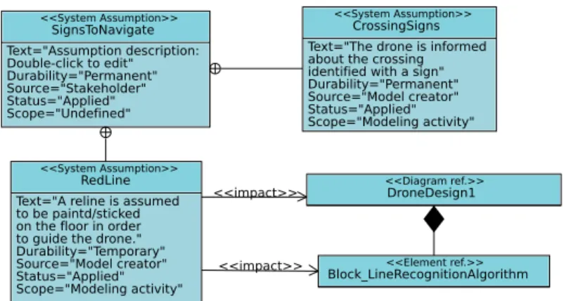
The first model considers only the first scenario. The corresponding MAD is given in Figure 1. The main assumption concerns the signs that are necessary to navigate, in particular the red line located on the floor. DroneDesign1 handles that line-based guidance, and implements it, in particular, with a block named LineRecognitionAlgorithm, see Figure 2.
<<impact>> <<impact>> <<System Assumption>> SignsToNavigate Text="Assumption description: Double-click to edit" Durability="Permanent" Source="Stakeholder" Status="Applied" Scope="Undefined" <<System Assumption>> RedLine Text="A reline is assumed to be paintd/sticked on the floor in order to guide the drone." Durability="Temporary" Source="Model creator" Status="Applied" Scope="Modeling activity" <<System Assumption>> CrossingSigns Text="The drone is informed about the crossing identified with a sign" Durability="Permanent" Source="Model creator" Status="Applied" Scope="Modeling activity" <<Element ref.>> Block_LineRecognitionAlgorithm <<Diagram ref.>> DroneDesign1
Fig. 1. Modeling Assumption Diagram - version 1
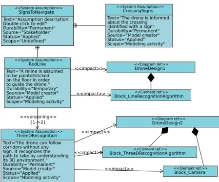
In scenario 2, the drone does not follow a line anymore, but uses images from the camera to detect paths to follow and obstacles. The RedLine assump-tion is thus now deprecated and replaced by a new assumpassump-tion named Three-DRecognition (see Figure 3). The design named DroneDesign2 handles that new assumption by two means. First, the introduction of a new block named Three-DRecognitionAlgorithm and second, the modification of the block Camera.
<<datatype>> Command - pitch : int; - roll : int; - yaw : int; - mode : int; <<block>> Camera - p : Picture; - x : int; - interframeDelay = 20 : int; - bottom = true : bool; ~ out sendPicture(Picture p) ~ in stopMe() ~ in startMe() <<block>> EngineController - lastCommand : Command; - currentPosition : Command; ~ in getCommand(Command c) ~ out sendPosition(Command c) <<block>> MainController - nbOfCrossings : int; - aliveTimer = 100 : int; - mode : int; - currentPicture : Picture; - movementTimer : Timer; - command : Command; - movementDelay = 100 : int; - found : bool; - position : int; - hasCurrentPicture : bool; ~ out sendCommand(Command c) ~ in getPosition(Command p) ~ in readNextPicture(Picture p) ~ out startCamera() <<block>> LineRecognitionAlgorithm
- found = false : bool; - foundI : int; - position : int; - minComputationTime = 30 : int; - maxComputationTime = 50 : int; - p : Picture; ~ in compute(Picture p) ~ out result(bool found, int position)
<<datatype>> Picture - sizeH = 0 : int; - sizeV = 0 : int; - data = 0 : int; - bottom : bool; <<block>> RemoteUser - place : int; - status : int; ~ in placeReached() ~ in missionAborted(int status) ~ out reach(int place)
<<block>> CrossingRecognition
- foundI : int; - found = false : bool; - p : Picture;
- minComputationTime = 10 : int; - maxComputationTime = 10 : int; ~ in compute(Picture p) ~ out result(bool found)
Command values: ---0: negative value 1: nothing 2: positive value Command mode: ---0: must take into account pitch, roll and yaw 1: takeOff 2: land
Fig. 2. Avatar block instance diagram - Drone Design 1
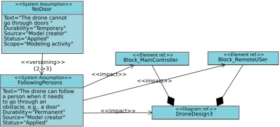
At last, scenario 3 takes into account the fact that the drone can go through doors. It means that scenario 2 was assuming there was no door (but negative assumption are more rarely expressed), and scenario 3 now assumes that a person must assist the drone to go through doors. A new MAD is thus used to express those new assumptions (see Figure 4). In particular, the temporary ”NoDoor” assumptions applies until version 2, but no more in version 3, in which the ”FollowingPersons” applies.
The design DroneDesign3 (see Figure 5) handles the FollowingPersons as-sumption. Modifications to meet that assumption impact two blocks: MainCon-troller and RemoteUser. The two blocks are enhanced with signals (e.g., DoorDe-tected, DoorHandled ), attributes and their state machine diagram can handle the new situation (going through doors).
4.3 Discussion and limitations
The case study demonstrates the facility to manage assumptions for different versions of the same system: assumptions, as well as their main characteristics can easily be captured, and the versioning is explicit in the diagram. The impact of modifying assumptions can be traced both at diagram level, and at modeling elements level.
<<versioning>> {1->2} <<impact>> <<impact>> <<impact>> <<impact>> <<impact>> <<System Assumption>> SignsToNavigate Text="Assumption description: Double-click to edit" Durability="Permanent" Source="Stakeholder" Status="Applied" Scope="Undefined" <<System Assumption>> RedLine Text="A reline is assumed to be paintd/sticked on the floor in order to guide the drone." Durability="Temporary" Source="Model creator" Status="Applied" Scope="Modeling activity" <<System Assumption>> CrossingSigns Text="The drone is informed about the crossing identified with a sign" Durability="Permanent" Source="Model creator" Status="Applied" Scope="Modeling activity" <<System Assumption>> ThreeDRecognition Text="the drone can follow corridors without any sign. It recognizes the path to take by understanding its 3D environment." Durability="Permanent" Source="Model creator" Status="Applied" Scope="Modeling activity" <<Element ref.>> Block_LineRecognitionAlgorithm <<Diagram ref.>> DroneDesign2 <<Diagram ref.>> DroneDesign1 <<Element ref.>> Block_ThreeDRecognitionAlgorithm <<Element ref.>> Block_Camera
Fig. 3. Modeling Assumption Diagram - version 2
Consistency checking inside of Modeling Assumption Diagrams, and with regards to referenced elements, has also been defined. For example, concerning versioning, an assumption modeled as deprecated in version x, should not itself deprecate another assumption in version x. For referenced elements, if an ele-ment, e.g., a block, meets a new assumption in version x, it should be different from the same block in version y with y < x. TTool already partly performs these coherency checking, which are necessary for correctly handling assump-tions traceability and interest. Similarly, helping the designer to rework the MAD while improving the other diagrams is a point that we intend to address in a near future.
Currently, one needs to open a MAD to see which elements are impacted (<< impact >> relations) by given assumptions. It could also be interesting to vizualize directly on design diagrams the assumptions linked to elements, e.g., blocks, states of state machines. For example, when passing the mouse pointer over a given element, TTool could display in a popup window all the related elements. Table-oriented views could also be used to better trace assumptions and modeling elements, in the same way as TTool can currently make it for requirements.
Last but not least, TTool can perform simulation and formal verification of safety and security properties on designs. However, TTool cannot (yet) use the modeling assumption diagrams to evaluate which parts of the design have
<<versioning>> {2->3}
<<System Assumption>>
NoDoor Text="The drone cannot go through doors " Durability="Temporary" Source="Model creator" Status="Applied" Scope="Modeling activity" <<System Assumption>> FollowingPersons Text="The drone can follow a person when it needs to go through an obstacle, e.g., a door" Durability="Permanent" Source="Model creator" Status="Applied" <<Diagram ref.>> DroneDesign3 <<Element ref.>> Block_RemoteUSer <<Element ref.>> Block_MainController <<impact>> <<impact>> <<impact>>
Fig. 4. Modeling Assumption Diagram - version 3
evolved - using the << impact >> relation - in order to restrict the proof to the properties that still have to be proved again in a new design version.
5
Related Work
A survey of the literature indicates that numerous authors (e.g. [14] [15]) share the following idea: specifying the assumptions is a system-engineering task.
[14] adds that ”model assumptions must be stated explicitly”. [17] says ”Some authors treat a list of assumptions as if were a conceptual model. It is not; but a conceptual model should include a list of assumptions”. [18] further states ”We want to have an argument that increases our confidence that the model represents the system correctly”. Therefore we document some of the modeling decisions in form of a list of the systems assumptions made while modeling. Given a real-time system boiled down to a controller and an environment termed as ”plant”, [18] categorizes assumptions that respectively apply to the system’s components, to the properties related to the mechanical, electrical and software that form the aspects of a system.
[16] categorizes the artifacts of conceptual modeling into ”knowledge acquisi-tion” and ”model abstracacquisi-tion”. The former demands to acquire knowledge about the real world and to derive a system description. The latter abstracts a concep-tual model from a system description, which implies specifications are made.
[10] further categorizes assumptions into technical assumptions, organiza-tional assumptions and managerial assumptions. Examples of technical assump-tions include programming languages as well as database and operating systems. Conversely, the paper advocates for a clear distinction between the system’s en-vironment (in terms e.g. of network connection and operating system) and the modeling or programming language used to design and develop the system. In
<<datatype>> Command - pitch : int; - roll : int; - yaw : int; - mode : int; <<block>> Camera - p : Picture; - x : int; - interframeDelay = 20 : int; - bottom = false : bool; ~ out sendPicture(Picture p) ~ in stopMe() ~ in startMe() <<block>> EngineController - lastCommand : Command; - currentPosition : Command; ~ in getCommand(Command c) ~ out sendPosition(Command c) <<block>> MainController - nbOfCrossings : int; - aliveTimer = 100 : int; - mode : int; - currentPicture : Picture; - movementTimer : Timer; - command : Command; - movementDelay = 100 : int; - found : bool; - position : int; - hasCurrentPicture : bool; - oldMode : int; ~ out sendCommand(Command c) ~ in getPosition(Command p) ~ in readNextPicture(Picture p) ~ out startCamera() ~ out stopCamera() ~ in reach(int place) ~ out missionAborted(int status) ~ out placeReached() ...
<<block>> ThreeDRecognitionAlgorithm - found = false : bool; - foundI : int; - position : int; - minComputationTime = 30 : int; - maxComputationTime = 70 : int; - p : Picture; ~ in compute(Picture p) <<datatype>> Picture - sizeH = 0 : int; - sizeV = 0 : int; - data = 0 : int; - bottom : bool; <<block>> RemoteUser - place : int; - status : int; - doorTime = 100 : int; ~ in placeReached() ~ in missionAborted(int status) ~ out reach(int place) ~ in doorDetected() ~ out doorHandled() <<block>>
CrossingRecognition - foundI : int; - found = false : bool; - p : Picture;
- minComputationTime = 10 : int; - maxComputationTime = 10 : int; ~ in compute(Picture p) ~ out result(bool found)
Command values: ---0: negative value 1: nothing 2: positive value Command mode: ---0: must take into account pitch, roll and yaw 1: takeOff 2: land
Fig. 5. Avatar block instance diagram - version 3
terms of organizational assumptions, our paper does not cover all the issues (de-velopment team, workflow, company standard) addressed by [10], assuming the method associated with AVATAR is compatible with the practice in use in the company. Also, the paper does not address managerial assumptions. Finally, [10] associates assumptions to architectural models and therefore to design decision where the paper also enables to link assumptions to analysis and behavioral diagrams.
[17] defines an assumption and the way a system uses it. [17] terms as ”refer-ent” the model or system component that the assumption is about; it compares to the ”impact” relation in MADs. Also, [17] terms as ”scope” a description of which parts the assumption refers to; it compares to the ”impact” relation in MADs. [17] also distinguishes between the system and its components.
Assumptions management is a key issue for versioning. [17]’s classification on change management in the context of requirement diagrams may be a source of inspiration for classifying the operations associated with a << versioning >> relationship: (1) New assumption added, (2) Existing assumption removed, (3) Part remove from an assumption, and (4) New part added to an assumption. Whatever the operation, the effect of applying a new modeling assumption at the end side of a << versioning >> relation may easily span over several diagrams. Evaluating that effect may rely on a dependency graph computed from the relations that link assumptions to diagram and diagram elements.
The tutorial in [8] mentions ”List requirement and assumptions” as an early stage of a process applied to a distiller. The authors use the ”Rationale” keyword to characterize an assumption described in a comment. The latter is attached to a requirement. Nothing is said about the traceability of the assumption made as a comment.
[20] addresses assumptions in a UML/SysML context. The paper proposes to extend UML/SysML with contracts. A contract associated with one compo-nent is a pair (assumption, guarantee) where an assumption is abstraction of the component’s environment behavior and the guarantee is an abstraction of the component’s behavior given that the environment behaves according to the assumption.
[19] also addresses assumptions in a SysML context. Given safety require-ments arise from assumptions about the system’s context, [19] introduces the concept of environmental assumptions and describes them by two means: SysML parametric diagrams for continuous properties of a hardware entity, and OCL constraints for discrete properties of a software entity. Besides standards, cus-tomers and domain experts, environmental assumptions belong to the list of sources the requirements come from.
6
Conclusions
A model is hard to understand and transmit as long as one ignores the assump-tions made by the engineers who elaborate that model. Therefore, the authors of the paper strongly advocate for an explicit inclusion of modeling assumptions inside the model. The paper implements the idea in the context of AVATAR, the real-time variant of SysML that is supported by the TTool tool. Adding Modeling Assumption Diagrams to AVATAR is the main purpose of the paper. A MAD defines a set of modeling assumptions nodes that describe and catego-rize the assumptions made to elaborate the model. A complex assumption may be split up into elementary ones. A versioning arrow between two assumptions enables to achieve versioning. Also, an assumption may be linked to a diagram it has an influence on. Precision may be added on the way diagram elements are impacted by the diagrams themselves influences by one or several assumptions. The autonomous UAV that serves as case study is a real UAV
(https://www.youtube.com/watch?v=tamYpmGvzRw).
All the diagrams presented in the paper have been edited using TTool.
The concept of Modeling Assumption Diagram could be applied to OMG’s SysML and to UML, as well as to UML profiles in general. The concept of versioning deserves further investigations in the view of optimizing the simulation and formal verification activities that may applied on AVATAR models.
References
1. OMG, ”System Modeling Language, specification v1.4”, http://www.sysml.org/, 2015.
2. Ludovic Apvrille, Pierre de Saqui-Sannes, ”Static analysis techniques to verify mu-tual exclusion situations within SysML models”, 16th International System Design Languages Forum, Montreal, Canada, Juin 2013.
3. Ludovic Apvrille, Yves Roudier, ”SysML-Sec: A SysML Environment for the Design and Development of Secure Embedded Systems”, Proceedings of the IN-COSE/APCOSEC 2013 Conference on system engineering, Yokohama, Japan, September 8-11, 2013.
4. Ludovic Apvrille, ”TTool, a free UML/SysML modeling software”, http://ttool.telecom-paristech.fr/
5. http://www.uppaal.org/
6. OMG, ”The UML Profile for MARTE: Modeling and Analysis of Real-Time and Embedded Systems V1.1”, http://www.omgmarte.org/, 2011
7. ”SoCLib, an open platform for virtual prototyping of multi-processors system on chip (MP-SoC)”, http://www.soclib.fr/
8. S. Friedenthal, A. Moore, R. Steiner, OMG Systems Modeling Language, tutorial, 19 June 2008, http://www.uml-sysml.org/documentation/sysml-tutorial-incose-2.2mo 9. R.D. King, C.D. Turnitsa, The Landscape of Assumptions, SpringSim ’08,
Proceed-ings of the 2008 Spring simulation multiconference, Pages 81-88
10. Lago, P. and van Vliet H., Explicit assumptions enrich architectural models, 27th Int. conference on Software engineering, St. Louis, MO, USA, 2005.
11. Towards Requirements Aware Systems: Run-time Resolution of Design Assump-tions, 26th IEEE/ACM International Conference on Automated Software Engineer-ing (ASE), Lawrence (KS), USA, 2011.
12. J. Marincic, A. Mader, A. Wieringa, Capturing Assumptions while Designing a Verification Model for Embedded Systems, January 2007.
13. Ludovic Apvrille, Alexandre Becoulet, ”Fast and Multi-platform Prototyping of Embedded Systems from UML/SysML Models”, The 14th edition of the Sophia Antipolis MicroElectronics Forum (SAME’2011), Sophia Antipolis, France, Oct. 12-13, 2011.
14. H. Kopetz, P. Puschner, RT System Modeling, TU Wien, May 2013, http://ti.tuwien.ac.at/cps/teaching/courses/real-time-systems/slides/rts03 rt model.pdf
15. F. Kordon, J. Hugues, A. Canals and A. Dohet, Embedded Systems: Analysis and Modeling with SysML, UML and AADL, ISTE / Wiley, May 20, 2013, ISBN-13: 978-1848215009.
16. K. Kotiadis, S. Robinson, Conceptual Modeling: Knowledge Acquisition and Model Abstraction, Winter Simulation Conference, Miami, FL, USA, December 2008. 17. R. D. King, C. D. Turnitsa, The Landscape of Assumptions, Proceedings of the
2008 Spring simulation multiconference, San Diego, CA, USA, Pages 81-88.
18. J. Marincic, A. Mader, R. Wieringa, Classifying Assumptions Made During Re-quirements Verification of Embedded Systems. In: 14th International Working Con-ference on Requirements Engineering: Foundation for Software Quality, REFSQ 2008, 16-17 June 2008, Montpellier, France (pp. pp. 141-146).
19. Shiva Nejati, Mehrdad Sabetzadeh, Davide Falessi, Lionel Briand, Thierry Coq, A SysML-Based Approach to Traceability Management and Design Slicing in Sup-port of Safety Certification: Framework, Tool SupSup-port, and Case Studies, Journal of Information and Software Technology, Volume 54 Issue 6, June, 2012, Pages 569-590. 20. Iulia Dragomir, Iulian Ober, Christian Percebois, Integrating verifiable As-sume/Guarantee contracts in UML/SysML, ACESMB@MoDELS, volume 1084 of CEUR Workshop Proceedings, CEUR-WS.org, (2013)
21. Daniela Genius, Ludovic Apvrille, Virtual Yet Precise Prototyping: An Automotive Case Study, Proceedings of the ERTS’2016, Toulouse, France.