OATAO is an open access repository that collects the work of Toulouse
researchers and makes it freely available over the web where possible
Any correspondence concerning this service should be sent
to the repository administrator:
[email protected]
This is an author’s version published in:
http://oatao.univ-toulouse.fr/25345
To cite this version:
Lacaze, Jacques
and Connétable, Damien
and Castro-Román, Manuel
Jesus Effects of impurities on graphite shape during solidification of
spheroidal graphite cast ions. (2019) Materialia, 8. 100471. ISSN 2589-1529
Official URL:
https://doi.org/10.1016/j.mtla.2019.100471
Effects of impurities on graphite shape during solidification of spheroidal
graphite cast ions
Jacques Lacazea.•, Damien Connétable
a, Manuel Jesus Castro-Roman
b • CIRIMAT, UniYemti de Toulouse, ENSIACEI', CS 44352, 31030 Toulouse Cedex 4, France• CINVESTAV Saltillo, Av. lndustria Metahlrg-ica 1062, Parque lndustrial Saltillo-Ramos Ari.?pe, Ramos Arizpe, Coahuila 25900, Mexico
ARTICLE INFO ABSTRACT
Keyword.s: Cast iron Solidification microstructure Graphite morphology Graphite degeneracy DFT
Since the discoveiy that magnesium and cerium (and more generally rare earths) added at low level to cast iron melts lead to spherodized graphite, it is lmown that some other elements are detrimental even when present as traces. In ail practicality, it bas soon been recogniz.ed that adding rare earths to the melt helps counteracting the effect of these detrimental elements. Accordingly, only few works have been devoted to studying the effect of trace elements in melts without any rare earths. This is the first aim of the present work to review those studies as they contain the material to understand the mechanism for spheroidal graphite degeneracy.
From this review, three types of degeneracy have been defined which show up when the critical level of any particular element is exceeded. These results are then discussed to show that ail degeneracies certainly proceed in the same way. To substantiate this discussion, the growth of compacted graphite as obtained by low level treatrnent of cast iron melt with magnesium is also presented. Finally, a mechanism is suggested for describing the action of trace elements on spheroidal graphite degeneracy. This mechanism is partly substantiated by first principles calculations which showed that ail elements can strongly adsorb on the prismatic planes which are the planes on which carbon atorns add on during graphite growth.
1. Introduction
Understanding growth of spheroidal graphite remains a challenge for both geologists [1] and metallurgists [2]. As a matter of fact, graphite
spheroids present structural characteristics which are unique and are definitely not tackled by simulation at meso scale such as phase field approach, see e.g. the extensive work on spherulite growth performed by Granazy et al. [3]. For metallurgists, an even more fascinating curiosity
is
the capability of low level and trace elements to affect spheroidal growth and to lead to various shape changes, bei.ng them expected or unwanted.In the world of metallurgy, spheroidal graphite irons is a relatively new foundry material dating back to the patent by Millis et al in 1949
[ 4), though various previous historical records have been reported [5]. The negative effect of trace elements on graphite nodularity was already mentioned in the patent but it was very soon realized that adding rare earths (RE) would offset the problem in most cases [6]. In practice, the classical magnesiurn treatment for spheroidizing cast iron melts is thus reinforced by addition of RE. Accordingly, many works have been de voted at optimizing the amount of RE to be added to counteract the presence of impurities, and much less have been concerned with the de
• Corresponding author.
E-mail address: [email protected] (J. Lacaze).
scription of the impurity effect without RE addition, i.e. concerned with describing and understanding this effect
The impurities listed in the patent [4] are As, Bi, Pb, Sb, Se, Sn and Te, and it
is worth stressing that most of them are also harmful
to non spheroidized lamellar graphite iron melts as reviewed by Rey naud [7]. In an extensive study aimed at controlling the charges for melt preparation, Thielemann [8] proposed the following quality index Sb for spheroidal graphite cast irons where Al and Ti appear but not Se and Te which were not considered:Sb
= 1.6 • w
Al+
2.0 · wAs+
370 · We;+
290 · WPb+
5.0 · Wsb+2.3. Wsn +4.4 . WTi (1)
in which W;
is
the weight fraction of i element in the charge used for preparing the melt This quality index has been obtained with spheroidal graphite cast irons containing 0.04 to 0.08wt.
% Mg that were cast with wall thickness in between 8 and 45 mm. When S.,is
lower than 1 no actionis
necessary while if itis
higher RE should be added to avoid spheroidal graphite degeneracy.What is seen in the Thielemann's factor and which reflects foundry practice is that bismuth and lead have a much higher coefficient than the other poisoning elements. This would not change if their content was expressed in mole fraction and this difference suggests that the mechanism of their action may differ in some way from that of the other elements. It was the aim of the present work to rationalize ex perimental observations and characterizations to suggest a mechanism ht1ps://doi.org/10.1016/j.mtla.2019.100471
Growth rate
Oecreaslng S
âT
for spheroidal graphite degeneracy appearing during solidification. lt was thought of intere;t to first consider the various "standard" fonns of graphite in lamellar, spheroidal and compacted graphite cast irons, including works on synthetic Fe C (Si) and Ni C alloys. Then, a review of metallographic observations of graphite degeneracy induced by irn purities and low level additions in RE free spheroidal graphite irons is pre;ented. Finally, a number of deductions are made and discussed, and an attempt to rationalize the role of these elements with the help of first principles calculations is carried out
2. Lamellar, spheroidal and compacted graphite
Without any special attention, a reasonably clean charge to prepare a cast iron melt consists of a Fe C Si alloy with possibly some alloying metallic elements (Cr, Cu, Mn, .. ) and low level amounts of oxygen and sulphur. Upon solidification in the stable system, this will give rise to flake graphite at low cooling rate and to undercooled graphite at high cooling rate. The transition is related to increased branching of the flakes in undercooled graphite as compared to lamellar graphite which can be accomplished by twinning [9,10].
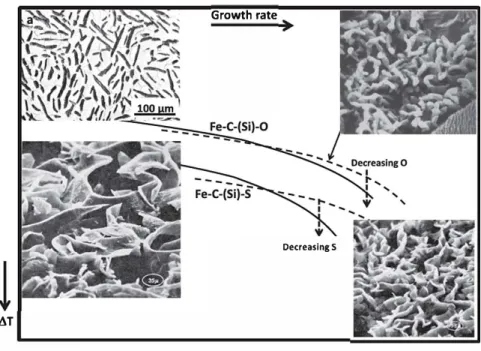
When studied by directional solidification experiments, the transi lion has been sometimes reported to be abrupt in terms of character istic inter lamellar distance [9], while for others both morphologies can coexist in a range of growth conditions [11]. From cooling curves and microstructure recorded on castings of various sizes, Thorgrirnsson [12] found that the transition occurs at an eutectic undercooling .6.T of about l0'C, a value in agreement with later estimate by Park and Ver hoeven [10]. ln Fig. 1, the two lower curves illustra te schematically that the eutectic undercooling of the;e two eutectics increases with growth rate (e.g., as irnposed by directional solidification). lt is there assumed that the evolving microstructure at given growth rate is the one having the lowest undercooling, or equivalently the highest growth tempera ture [11]. The micrographs along these curves illustrate that the spacing between graphite flakes is much smaller in undercooled graphite than in lamellar graphite.
If the melt is purified, i.e. that oxygen and sulphur are decreased to very low levels, flake graphite is changed to plate like at low growth rates in Fe C (Si) alloys [13,16,17] and in Ni C alloys as well [18 20]. This graphite shape cliffers from lamellar graphite by showing little branching, having straight outer boundaries and even thickne;s see Figs. 1 and 2. With increased growth rate, the plate like graphite changes
-,
,
'
1 \I
Fig. 1. Change of eutectic undercooling .O. T ver.ms growth rate for the four types of lamellar graphite coupled eutec tics. Mi crographs are from Ruth and Tmpin [13] for plate graphite (a), Lux et al. [14] for coral graphite (b), and Day [15] for flalœ (c) and undercooled (d) graphite.
�
;.>
"�-��,,
,
✓
I ,
'
Fig. 2. Graphite plates and spheroids in a rapidly solidified pure Fe-C-Si alloy [30]. Alloy with 2.81 wt.% carbon and 9.91 wt.% silicon.
to coral graphite which cliffers from undercooled graphite, compare mi crographs b and d in Fig. 1. At a lime when alternative fonns of graphite in cast irons were looked for, Campomanes and Groller [21] found that addition of Zr which is a strong deoxidiser changed lamellar graphite to coral graphite in castings made from cast irons with very low level of sulphur (less than 20 ppm). At a slightly higher level of S of 60 ppm, Liu and Loper [22] observed a more complex series of transitions with de creasing cooling rate in a wedge casting: from spheroidal to compacted, then to coral and then to undercooled graphite. This suggests that the maximum level of S for having coral graphite instead of undercooled graphite increases with increase in the cooling rate.
Coral graphite has sometimes been described as fibre like [17]; it resembles a rod like eutectic but is highly branched and thus appears irregularly distributed [10]. Considering pure enough melts, there must be a critical growth rate at which plate like graphite is replaced by coral graphite as sugge.ted by the two upper curves in Fig. 1. ln this figure, the relative positioning of the curves for plate like and flake graphite in terms of undercooling relies on the result by Lux and Kurz [17] who showed sulphur decreases the growth temperature of the austenite graphite eutectic. This may be due to both or either: (i) sulphur being rejected by austenite at the two phase solidification front decreases the
Fig.3. Comparison of the microstructure of lamellar (a) and compacted (b) graphite cast irons solidified in a thermal cup. Courtesy of IK4-Azterlan.
localreferenceeutectictemperature [23,24];(ii)anintrinsiceffectof sulphuronthegrowthmechanismofgraphiteoroftheeutectic cells
[25].
Whatfinallysuggests Fig.1isthatsulphurandoxygendonotaf fectgraphitegrowthinthesameway.Thisgoes inlinewiththeob servationbysecondaryionmassspectroscopy(SIMS) [26]andAuger spectroscopy [10]thatsulphuradsorbsonbasalplanesandoxygenon prismaticplanesofgraphite.
All four structures described above result from coupled austen ite/graphiteeutecticgrowth.InthecaseofsynthetichypereutecticFe C, Fe C SiorNi Calloys,primarysolidificationofgraphitegivesalsoriseto plate likelamellae[20,27].Increasingthecoolingrateleadstosimulta neousgrowthofprimaryplate likelamellaeandspheroidsasillustrated in Fig.2.Increasingfurtherthecoolingratemayeliminatethelamel laeleavingonlyspheroids [18,20].Thissimpleschematicoftheeffect ofcoolingrateongraphiteshapeinpurealloysisgenerallyaccepted. Inone investigation using directionalsolidification, growthof coral graphitehasbeenreportedandatransitionfromcoral tospheroidal growthhasbeenobserved [28].Evenmoresignificant, Dhindawand Verhoeven [28]noticedthesuppressionofspheroidalgraphiteinout gassedmeltsmadefromhighlypurematerials.Theauthorssuspected this suppressiontobe duetothe disappearance ofany graphitenu cleationsubstrates.This meansthat coupledgrowthof graphiteand austenitewouldbepreferredevenathigheutecticundercoolinginpure ironmelts,unlessspheroidalgraphitemaynucleateaheadofthecou pledsolidificationfront.Finally,itshouldbementionedthatMuham madandFredriksson [29]have recentlyreportedprimary precipita tion of rod like graphite with more or lesscircular section ascoral graphite.1
Inallpracticality,addinganinoculanttoacastironmelteasesso lidificationinthestablesystem,whileaproperspheroidizingtreatment (withmagnesiumormagnesiumandRE)triggersspheroidalgrowthin steadoflamellargrowth.Itisworthmentioningherethatcompacted graphiteisobtainedmostcommonlywithlowleveladditionofmagne sium,thoughothermethodsexist [31 33].Ifthefirsteffectofmagne siumistotightoxygenandsulphurasgenerallyaccepted,thenconsid eringagainFig.1isofinterest.Indeed,NieswaagandZuithoff[9]have
1 In a private discussion during the conference EUROMAT-2019, Muhammad clarified that the wording “primary precipitation ” in ref. [29]means growth ahead of a austenite/graphite coupled eutectic front.
shownthatdecreasingthesulphurlevelinFe C (Si) Salloysdoesin creasethecriticalgrowthrateforthetransitionbetweenlamellarand undercooledgraphite(their Fig.3),seethelowerverticalinterrupted arrowin Fig.1.Similarly,ParkandVerhoeven [10]havenoticedthat decreasingtheoxygenlevelinthemeltincreasesthecriticalvelocityfor plate liketocoralgraphitetransition,seetheupperverticalinterrupted arrow.Hence,byremovingoxygenandsulphur,lowleveladditionof magnesiummadetoacastironmeltdecreasesthebranchingcapability ofgraphite.ThisisinfactwhatisobservedinFig.3wherearecompared themicrostructuresofacompactedgraphiteandofalamellargraphite castironsthathavebeensolidifiedinthesameconditions(thermalcup)
[34].Itisseenthatthegraphitelamellaaremuchcoarserandmuch lessbranchedincompactedgraphitethaninlamellargraphitematerial. Thispeculiarshapehasbeencomparedtowormsbutithasbeendemon stratedthattheseare2Dsectionsofinterconnectedwavyandirregular lamellas[35 38].
Itis wellacceptedthatplate like,flakeandundercooledgraphite dogrowalongtheprismaticdirection.Thestructureofcoralgraphite hasbeeninvestigatedbyLuxetal. [14,39]andbyParkandVerhoeven
[10].Bytransmissionelectronmicroscopy,Luxetal. [14]established that graphitelayersin coral graphitehavethe[0002] directionper pendiculartothesurfaceofthebranches,meaningcoralgraphitegrows alsointheprismaticdirection.However,bothstudiesreportedthatcoral graphitecontainsmuchmoredefectsandorientationchangesthanany oftheothergraphiteforms.Thereisunfortunatelynotmuchdetailed workreportedonthemechanismofgraphitebranching.InpureNi C alloy,DoubleandHellawell [19]demonstratedthatplatesofgraphite growwithapreferred < 1120> directionandbranchintheplaneofthe graphitesheetsasschematicallyillustratedwith Fig.4a.Theseplates aremadeof astackof perfectcrystalstypically100nmin thickness each thatmaybe rotatedbetweeneachotherfollowingso calledco incident stackingwith anglesof about13,22 and28deg. They also presenttwinningacross[11̄2 1]reflexionplanewhichleadstobending ofthebasalplanethrough20°45′witha < 1̄1 00> rotationaxis.How ever,these twinsdo notappeartodevelopoutof thesheetplanein plate likegraphitewhiletheydoinflakeandundercooledgraphite[10], seeFig.4b.Theseobservationssuggestthatdifferentbranchingmech anismsoperateduringplate likeandflake likeorundercooledgraphite growth,i.e.dependingonthefactthatsulphurispresentornot.Coral graphiteshowsbothanenhancedbranchingmechanism [14,39]anda modificationofthegrowthshape[10,19,29]asinthecaseofsiliconin Al Sieutectic[40,41]afterso calledmodificationwithstrontium.
Fig.4. The branching mechanisms of graphite [9]: in-plane branching (a), branching by twisting (b), and combination of both (c).
As will be seen in the following, the above description of usualgraphiteshapesin castirons isinstrumental forunderstanding spheroidal graphitedegeneracy. Indeed, compacted graphitemaybe seenasonesuchdegenerateformofspheroidalgraphite.
3. Effectofselectedimpuritiesonspheroidalgrowthofgraphite
Asseenintheprevioussections,spheroidalcast ironsareFe C Si alloyswithadditionofaspheroidizersuchasmagnesiumoramixof magnesiumandRE.Theyalsocontainlowlevelsofoxygenandsulphur, aswellassomegases(hydrogenandnitrogen)dissolvedintheliquid, andimpuritiesmostoftencomingfromrecycling.BecauseREareprone totightmostoftheelementsascompounds,thepresentreviewwaslim itedtoobservationsonRE freecastironswiththehopethatsomeclear trendswouldshow up.Althoughrecentreviewsareavailable [7,42], thisisquiteoldandscarceliterature.Further,onlyadditionswithinthe rangesfoundinpracticehavebeenconsideredbecausehigheradditions mayleadtootherkindsofgraphitedegeneracy[43].Somedetailedin formationhasbeenfoundregardingAl,Bi,Pb,SbandTi,towhichitwas consideredadequatetoaddMg.Moreover,onlysingleadditionswere consideredthoughtheirpossibleinteractionsareofadefinitepractical importance.
Inmanyofthereports,emphasisisputontheeffectofcoolingrateon thetypeofgraphitedegeneracyobserved.Thishasbeenaccountedfor herebydifferentiating,wheneverappropriate,small andheavy section castingscorrespondingtohighandlowcoolingrates,respectively.Fig.5
illustratesthiscooling rateeffectinthecaseofacastirondopedwith
Fig.5. Optical micrographs of a spheroidal graphite cast iron doped with ti- tanium: a) with 0.16 wt.% Ti, cast as a 25 mm in diameter rod; and b) with 0.10–0.11 wt.% Ti cast as a 72 mm thick plate (b) [44].
Fig.6. Optical micrograph of spheroidal graphite cast irons: (a) doped with 0.11 wt.% antimony [45], etched with Picral; (b) over-treated with magnesium
[51].
titanium[44].Inarod25mmindiameter,titaniumleadstoworm like graphite(Fig.5a)whileinaplateof72mminthicknessanextended networkofmeshgraphiteisobserved(Fig.5b).Notealsothepresence ofdegeneratespheroidsandofspikygraphiteatthebottomof Fig.5b. Asimilareffectofcoolingratehasbeenreportedfortitaniumalsoby Gilbert[45].IthasbeenstressedbyHecht [44],andthisisclearlyseen inFig.5,thatthedegeneraciesarephysicallyconnectedtospheroids.
InMg treatedmelt,aluminiumgivesrisefirsttotheformationof spheroidsandthen,withtheprogressofsolidification,towormsasin compactedgraphiteiron [46].Theobservationofthemicrographsin theworkbyFarguesandMargerie [47]ona2wt.%Aland2wt.%Si spheroidalgraphitecastironshowsthatthewormsstartfromthenod ules,i.e.theyarenotnucleatedintheliquid.
With 0.02wt.% of antimony added to a cast iron melt, Gilbert
[45] reports the formation of spiky or lamellar protuberances until allspheroidshavedisappearedat0.09wt.%Sbin45mmkeel blocks. Thegraphiteaggregateshowevermaintainaquitecompactshape,see
Fig.6a,hencethecrab likedenomination.Similaraggregateshavebeen reportedbyBatesandWallace[48]andTybulczucketal.[49]asare sult ofSbaddition.Interestinglyenough, verylow leveladditionsof antimonyandarsenicgivehighlyspheroidalgraphiteparticles [49,50]
whichmaystillbepresentwhencrab likegraphitestartsappearing[45]. Itistotallyunknownifthisactionisadirectone,i.e.verylowlevelof
Fig.7. Micrographs showing: (a) the effect of 26 ppm of bismuth [42, 49], slow cooling rate; (b) the effect of lead on spheroidal graphite iron with 70 ppm of lead [7, 42], intermediate cooling rate (the scale was not reported but the di- ameter of the nodules is thought to be 30–40 μm).
theseelementsfavoursspheroidalshape,oranindirectonewherethese elementstightotherdetrimentaltraceelements.Finally,asforthecase ofantimonyandarsenic,excessoftinleadstocrab likegraphitedegen eracyaccordingtoThielemann [8].
Appropriatemagnesiumtreatmentrelatesto0.04 0.08wt.%resid ualmagnesium,with0.02 0.03wt.%freemagnesiumleftdissolvedin themelt [49,52].Incaseofover treatment,namelyfor0.10wt.%Mg andover, spheroidal graphite degeneracy is observed [8,51] thatis muchalikethatobtainedwithantimony,see Fig.6b.Sometimes,de generategraphiteduetomagnesiumappearsonlyinintercellularareas whereittakesaspikyorlacyshape [49,51].However,theconnection oftheseintercellularprecipitateswithgraphitespheroidsmaybeagain observed [51].Itisworthmentioningthatotherspheroidizers,namely rareearthelementsincludingyttrium,leadalsotocrab likegraphite whenaddedaboveacriticallevel [53].
Leadandbismuthleadtothesamekindofmeshgraphitewhichis illustratedinFig.7.Gilbert[45]classifieditascoarselamellargraphite, thusdifferentiatingthisshapefromthemorecompactcrab likeaggre gatesgeneratedbyantimonyaddition(see Fig.6a).Inarecentwork, Tonnetal. [54]havedemonstratedthephysical connectionbetween spheroidsandintercellulargraphiteinacastirondopedwithlead.In onecase,a crab likestructure hasbeenreportedin a castironcon taining50 60ppmof bismuthandcastasa30mm rod [55].Thiele mann[8]hasobservedsimilarlythatleadleadstocrab likegraphiteat lessthan20ppmwhichchangestomeshgraphiteathigherlevel.This stronglysuggestsacontinuumexistsbetweenalldegenerateformscon sideredinthepresentwork,namelyworms,crab likeandmeshgraphite. Further,andthoughitwouldbeofinteresttosubstantiatethiswithap propriateobservations,theshapeofthesedegeneraciesleadsthinking theymainlygrowalongtheprismaticdirectionofgraphiteasdoesflake graphite.
4. Discussion
When magnesiumis addedto cast ironmelts,it firsttights oxy gen andsulphur,andtheremaining whichis called free magnesium mayadsorbfreelyongraphite [25,52].Whiletheoverallorapparent growthdirectionofspheroidalgraphiteisalongthebasalplanedirec tion, the growthmechanisminvolves carbonatomsattaching tothe prismatic planesas previouslydiscussed [56]. Ithasbeen suggested thatspheroidizersadsorbontheseprismaticplanes [8,43,57],andthis hasbeenacceptedonthebasisoflaboratorystudiesonFe C Cealloys
[27].However,whenmagnesiumisaddedin excess,typicallyabove 0.08wt.%,protuberancesstartgrowingoutofnoduleswhicharemuch alikethoseseenwithantimony(Fig.6).Thisstronglysuggeststhatmag nesiumatomsarenowblockingtheadvanceofthegrowthstepsalong thesurfaceofthespheroidsandtriggergrowthofprotuberances.
Notethat theabove descriptiondoesnotgive adefiniteexplana tiontospheroidalgrowth.Thequestionhereisrathertoclarifyifthis schematicis ofany helptounderstandtheroleofimpurities onde generacyofspheroidalgrowth.Fromtheprevioussection,additionof so calledpoisoningelementsaboveacriticallevelleadstotheappear ance ofspikesatthesurfaceofthespheroidswhichthendevelopas worms.Theresultingmicrostructureisreminiscentfromthatofcom pacted graphite. Incaseof slow cooling,this crab like orworm like morphologyevolves inmeshgraphiteasis illustratedin Fig.5bfor thecaseoftitanium.Itisthusseenthatthereisacontinuousevolution fromcrab liketowormsandthenfromwormstomeshgraphite.
Inthepast,anumberoftheoreticalattemptstorationalizetheef fectoflowlevelelementsonspheroidalgraphitedegeneracieswerecar riedout.Inhisoutstandingreview,Lux [25]mentionedattemptsdone consideringelectronicdistributionoftheelementsandmetal non metal bindingenergies.Theseapproachesshowedhoweverquitelimitedap plicationandthissuggestedresortingtofirstprinciplecalculations.Be forediscussingsuchcalculations,itishoweverofinteresttonotethat theelementsmentionedinthepresentworkshowaninterestingsort ingwhenconsideringtheirdifferenceinelectronegativitywithcarbon, ΔEN ,usingPauling’sscale.ThisisdoneinFig.8wherethegreyedarea denotestherangeofvalueswherenon polarbondsareexpected.Inthis areaarefoundthetwo elementsthatareknowntoadsorb onbasal planes,sulphur [10]andtellurium [58].Oxygenhasastrong(nega tive)valueandisknowntoadsorbonprismaticplanes[26].Fig.8thus suggeststhatallelementsbutsulphurandtelluriumwillpreferentially adsorb totheprismaticplanesasdoesoxygen,withtheexceptionof antimonywhichis justatthelimitandmaywellgoequallyonboth sites.Notethatforelementswithhighatomicweight,Bi,PbandSb,the
Fig.8. Difference in electronegativity between carbon and various elements having an effect on graphite growth in cast irons.
1000
100
>-CD Mg10
1 eTi Sne
•sb
Ca'
'
10
100
Thielemann factor
s
1000
Fig. 9. Relation between Thielemann's factor Sb and the quantity Il. which char acterizes adsorption of i a toms on graphite.effect of van der Waals forces should have to be considered in addition to covalent bonds.
There have been numerous density functional theory (DFI') calcu lations on the interaction between foreign atoms and graphite layers, but only a few dealing explicitly with cast irons [29,59]. ln the annex are presented new DFI' calculations reporting values of adsorption en ergy and of the stable distance between a foreign atom and graphite. These calculations have been performed for adsorption on basal and prismatic planes. ln this later case, calculations were carried out for two configurations, the so called arm chair and zig zag configurations. The elements considered are C itself, and Al, Ca, Fe, Mg, 0, S, Sb, Sn, Te and Ti.
These calculations show that the adsorption energy of ail these ele ments is strongly negative on the zig zag position. For the arm chair con figuration, this adsorption energy is still significantly negative but with values often half those for the zig zag position. For the basal planes, the calculated adsorption energy is only slightly negative, being even slightly positive for Sb. It could thus be concluded that any element could adsorb on the basal planes apart for Sb but the calculations predict this will much more likely happen on the prismatic planes. It is worthy to note that the adsorption energy of magnesium is the lowest of ail the studied elements for the prismatic planes.
These calculations thus support the suggestion made above that for eign elements add up on the prismatic planes. S and Te appear however to be exception in that DFI' calculations do not predict their preferential adsorption on the basal planes. As a matter of fact, DFI' calculations are conducted for graphite in vacuum, not considering the metallic matrix with which graphite is in contact in cast irons. S and Te are in fact par ticular elements located in the same column in the Mendeleyev table
which are known to easily form associates with Fe, namely FeS and FeTe respectively. Such associates were already considered by Koza.ke vitch et al. [60] to explain the role of sulphur in cast iron melts. They have been aJso seen to be necessary for appropriate thermodynamic de scription of the Fe S [61,62] and Fe Te [63] systems. This suggests that the existence of these associates is the fundamental reason for S and Te to preferentially adsorb on basal planes. Molecular dynamics could cer tainly overta.ke the limits ofDFT calculations and one attempt has been
b
Fig. 10. Schematic of spheroidal growth of graphite following a 2D nucleation and growth model (a) where Mg atoms adsorb preferentially on the prismatic planes [56]. Formation of protuberances in case of too low Mg content (b) or of foreign element (red dots) adsorbing together with Mg on the prismatic planes (c).
reported recently [64] dealing with the effect of O on iron/graphite in terfacial behaviour.
The effect of any added atom on the prismatic planes should be proportional to the area it occupies and to the number of electrons on its outermost shells. Further, it was thought that the effectiveness of an added element would decrease when the difference in adsorp lion energy with that of carbon increases. Accordingly, the quantity A ( r; )2 (ne-); ,, ed wh · th · · di f ·
.... = ;:;;- · IEa,1(i)-Eac1CQI was eva,uat , ere ri IS e 1oruc ra us o 1 atom, (ne-); is the number of electrons on the outer shells of i atom and Ead (i) is the adsorption energy of i a tom. This quantity is plotted versus the Thielemenann's factor Si, (Eq. (1)) in Fig. 9, where the adsorption energy of Bi and Pb has been set to that of Te (Table A. 1 ). Owing to the fact that Mg and Ca are spheroidizers, they could be attributed a low value of 1 and 2 respectively in the expression of Si,. It is seen in Fig. 9 a good correlation between t:,. and Si, which stresses the importance of the size effect and the correlated number of outer electrons on the poisoning effectiveness of an element
Finally, a schematic for spheroidal graphite degeneracy may be sug gested on the basis of the growth model previously developed [56]. This model assumes that growth of graphite spheroids proceeds by nucleation of new growth blocks at the outer surface of the spheroids which then grow along that surface, see Fig. 10 a. This process works well as long as there is just enough Mg for limiting the lateral extension to the surface of the spheroid by adsorbing on the prismatic planes. ln case there is not enough Mg, graphite protuberances may develop in a direction tan gential to the surface, see Fig. 10 b. This is thought to be the process by which compacted graphite develops out from spheroidal graphite. ln the case foreign elements adsorb on the prismatic planes together with Mg, the growth may eventually be blocked in the prismatic direction, fore ing graphite to protrude away from the spheroid surface, see Fig. 10 c, as do spikes described in the previous section.
5. Conclusion
Analysis of the literature on the effects of trace elements on spheroidal graphite degeneracy suggests that a continuum exists betweenworms,crab likeandmeshgraphite.Thesedegeneraciescer tainlymainlygrowalongtheprismatic directionof graphiteasdoes flakegraphite,thoughthisclaimshouldbesubstantiatedbydedicated studies.Also,thesedegenerategraphiteformsshowlittlebranchingas doescompactedgraphite,inwhichcasethishasbeencorrelatedwith theverylowlevelsofSandOremaininginthemelt.Aschematicfor graphitedegeneracyhasbeenproposedthatreliesonadsorptionoffor eignatomsatthegraphitesurface.
Mostoftheimpuritieswhichareknowntoleadtodegenerateforms ofgraphiteduringsolidificationof spheroidalgraphitecast ironsare alsoknowntopromotepearliteduringtheeutectoidtransformation.As amatteroffact,themostusualreasonforapearlitepromotereffectis theblockingofferritegrowthbyhindranceofcarbontransferfromthe parentaustenitetographite.Thissuggeststhattheelementspoisoning spheroidalgraphitegrowthduringsolidificationkeepthiscapabilityat lowertemperaturewhentheiron richmatrixhasbecomesolid.
Inthefuture,moleculardynamiccalculationsshouldbepreferredto DFTcalculationswhichhavebeenshownnottopredictthepreferential adsorptionofSandTeonthebasalplanesofgraphite.Further,itshould beof firstinteresttoinvestigatetheinteractions offoreignelements betweeneachotherduringgraphitegrowthwithinaniron richmatrix. OwingtotheprominentroleofSandO,theirinteractionswiththetrace elementsconsideredinthisworkarecertainlyworthofinvestigation.
DeclarationofCompetingInterest
Noconflictofinterest.
Acknowledgments
DFTcalculationswereperformedusingHPCresourcesfromCALMIP (Grant2019 p0912).
Annex Abinitiocalculations
Calculations were performed using the VASP package [65]. The plane wavebasisprojectoraugmentedwave(PAW)method[66,67]and thePerdew Burke Ernzerhofgeneralizedgradientapproximationofthe exchangeandcorrelationfunctional(PBE) [68]wereemployedinthe frameworkofthedensityfunctionaltheory(DFT).Totakeintoaccount Van der Waalsinteractions,theTkatchenko Schefflermethod[69]with iterativeHirshfeldpartitioning [70]wasemployed.Calculationswere performedwithspineffectsandtheplane waveenergycut off wasset to1000eV.
FineMonkhorst Packmeshes[71]wereusedtosamplethefirstBril louinzoneofthesuper cells.Todescribebasalsurfaces72carbonatoms wereconsidered,i.e.3×3super cellsinthebasalplane,and2cellsin theperpendiculardirection, z ,meaning10×10×1kmeshes.Todeal withso calledprismaticplanes,twoconfigurationswereconsideredin thebasalplane,thearmchairandzigzagsurfaces.Forthearmchairsur face80carbonatomswereusedtobuild5×1×2super cells withthe vacuumalong y axis ,meaning10×1×20kmeshes.Thezigzagstruc turewascomposedof2graphenesheetsandwas5atomicplanesthick (72Catoms),meaningaswell10×1×20kmeshes.Alargevacuum wasintroducedinthesuper cells,about14Å,tominimizeinteractions betweensurfaces.
Thesystemwasfirstoptimizedforthecarbonatompositionsand shapeofthesuper cells.Theoreticallatticeparametersofgraphitewere thusfoundequalto2.46Å and6.74Å,whichagreewellwithexperi mentalvaluesat2.46Å and6.71Å. Firstprinciplescalculationswere thencarriedouttostudythepossibilityofadsorptionongraphiteofthe followingelements:C,Al,Ca,Fe,Mg,O,S,Sb,Sn,TeandTi.Thiswas
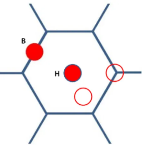
Fig.A.1. Added atom was initially located above the basal plane in four possible positions indicated with the two circles and two discs. The positions B and H refer to the most stable positions after relaxation. The hexagonal network of carbon atoms is depicted by the bonds represented with bold solid lines.
donebyaddingoneoftheseatomstothesystem.Onbothbasaland prismaticplanes,differentpossiblelocationsforaddingthisatomwere consideredasdescribedbelow.Tofinallyanalysetheinteractionofthe addedatomandgraphite,wedefinedtheadsorptionenergies,Ead ,by:
Ead =Eo [graphite+X]−Eo [graphite]−Eo
[ Xat
]
(A1)
whereEo correspondstotheDFTenergies,withEo [Xat ]theenergyof theisolatedXatom,Eo [graphite]andEo [graphite+X]beingtheenergy ofthesystembeforeandafteradditionofX,respectively.Forallcalcu lations,thedistancedX-Gr betweentheaddedatomandthetopofthe graphitesurfacewascalculated.
Forthebasalplane,fourpossibleinitialconfigurationsoftheadded atomwereconsideredwhichareshownwiththetwocirclesandtwo discs in Fig.A.1. Inmost ofthecases, thebridge(B) andhexagonal (H) positionsindicatedwithdiscswerefoundmost stableafterrelax ation.TheonlyexceptionwasSnwhichwaspredictedmoststablein topposition,i.e.aboveoneCatom.Ead anddX-Gr valuesarereported in TableA.1.AllelementsexcepttheSbatomshowanegativeenergy indicatingthepossibilityfortheiradsorption.Thecalculateddistance tothegraphiteplaneinthecaseofMgandTeishighinregardtoother specieswhichshowsadsorptionofthesetwoelementswouldbevery unlikely.Consideringthedistancetothegraphiteplanecalculatedfor theelementsthatcouldadsorb,itisseenthattheOatomisclosertothe graphitethanallotherspecies.Mostofthespeciesarelocatednearthe surface,atadistanceintherange1.4to2.1Å.Nevertheless,asimple discussionofadsorptionenergiesanddistancesisnotsufficienttoex plainwhysomespeciesprefertobeadsorbedonbasalplane.Theresults showthatFeisinstrongcompetitionwithallspeciesthatcanadsorbon thebasalplane.SinceFeisthemaincomponentintheactualsystem, itshouldformFelayersthatpreventtheadsorptionofotherspecies. Indeed,thereisastrongaffinitybetweenFeandCatoms.Forinstance, theSatomadsorbsfurtherawayandlessstronglythantheFeatom. Thepresentresultswouldthussuggestthatoxygencanadsorbeasily onthebasalplanewhileitwouldbemoredifficulttosulphur,whichis howeverjustoppositetoexperimentalevidence(seethemaintext).
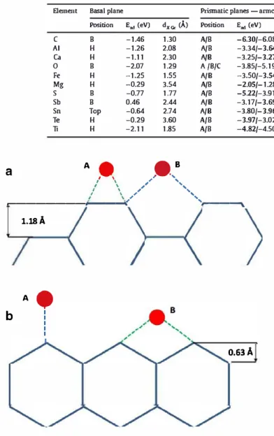
AsdepictedinFig.A.2,twopossiblepositionsAandBwereconsid eredforboththechair(Fig.A.2a)andzig zag(Fig.A.2b)configura tionsinthecaseoftheprismaticplanes.
Theresultsofthecalculationsforthechairconfigurationarealsore portedin TableA.1,whichincludethevaluesofEad anddX-Gr forboth AandBpositions,withthemoststablebeingshowninbold.Incontrast toallotherelements,calculationforoxygenledtoamoststableposi tionlocatednearaCatomanddenotedCinTableA.1,asdisplayedin
Table A.1
Results of the DFf calculations. For prismatic sites, the values corresponding to the most stable state are shown in bold. The star for O in arm-chair position indicates a particular position for this element, see text.
Element Basal plane Prlsmatlc planes -armchair Prlsmatlc planes - Zig-zag
Position B H H E.., (eV) -1.46 -1.26 -1.11 dx Go- (À) Position 1.30 A/B 2.08 A/B 2.30 A/8 E.., (eV) -6.30/-6.08 -3.34/-3.64 -3.25/-3.27 dx c, (À) Position 1.45/0.81 A/8 1.76/1.39 A/8 2.08/1.60 A/8 E.., (eV) -10.27/-10.86 -8.17 /-9.58 -8.28/-9.20 C Al Ca 0 Fe Mg s Sb Sn Te Ti B -2.07 1.29 A /B/C -3.85/-5.19/-5.37 1.32/1.18• /0.85 A/B -11.48/-9.71 1.34/0.99 1.96/1.58 2.19/1.90 1.23/1.l 3 1.85/1.33 2.03/1.65 1.66/1.46 1.89/1.86 2.10/1.89 2.03/1.81 1.90/1-44
a
H H B B Top H H -1.25 -0.29 -0.77 0.46 -0.64 -0.29 -2.11 1.55 A/8 3.54 A/B 1.77 A/B 2.44 A/8 2.74 A/8 3.60 A/B 1.85 A/B A -,.,8 / \ ,, ', I \ ,, ', -3.50/-3.54 -2.05/-1.28 -5.22/-3.91 -3.17/-3.69 -3.80/-3.96 -3.97 /-3.02 -4.82/-4.50/
\
,,'
',,
,---,----
·
----
...
b
1.18Â A� 1 1 1 1 10.63Â
Fig. A.2. Schematic of possible adsorption sites in the prismatic planes. The added atom (solid circles) was initially located in either of the two possible positions (A and B) ahead of the chair configuration (a) and of the zig-zag con figuration (b).
Fig. A.3. These values of the energy are always more negative than those for the basal plane, indicating a possible preference for adsorption on the prismatic planes. This may be explained by the presence of pending bonds (sp orbitals) which favour the hybridization with foreign atoms. Here, oxygen and sulphur show the most negative adsorption energies and the shortest distances to the graphite plane, though the distance for oxygen is smaller than for sulphur.
Calculations for the zig zag configurations generaily gave even higher adsorption energy than for the chair configurations as seen in Table A.1. Again, the energies and distances for oxygen and sulphur ap pear highly favourable for adsorption of these elements on the prismatic plane. It can be noted that the position B, which involves a C X double bond, is favoured in ail cases except oxygen. This suggests that a part for the O atom, this position ma.kes it possible to optimize interactions and thus to increase charge transfer. With regard to oxygen, the possibility of forming a O C double bond as in the CO molecule seems to be at the origin of the high stability of the A configuration. The do-Gr value was
1.69/1.35 A/8 1.87/1.46 A/8 1.65/1.23 A/8 2.03/1.66 A/8 2.05/1.73 A/8 2.04/1.59 A/8 1.82/1.52 A/8 -7.87/-8.74 -6.71/-7.96 -9.47 /-10.06 -7.96/-9.10 -8.39/-9.64 -8.35/-9.28 -9.15/-11.17
Fig. A.3. Position of the most stable added oxygen atom onto the chair config uration.
found at 1.23 Â which is only slightly higher than the C O distance at 1.1 Â in the CO molecule.
For both armchair and zig zag configurations, it was found that the distance of the most stable location of the added atom is slightly larger than the ideal distance in the graphite network. This difference has to do with the size of the added atoms. The B position in armchair con figuration leads to quite large bond length which may be further in creased by the size effect This certainly explains that the E.d values are significantly lower for the armchair configurations than for the zig zag
ones. For this armchair configuration, the Ead values are less negative for
added elements than for carbon. On the contrary, it is worth noting that the Ead values are more negative for O and Ti than for C in the zig zag configuration, indicating that these elements may adsorb preferentiaily to carbon.
In the literature, there seems to be only one work which considered similarly ail possible sites for adsorption on graphite. This is the work by Incze et al. [72) who studied the case of O adsorption. In this study, use was made of a slightly different functional (GGA PW91) with a very low value for convergence at 270 eV. However, the authors did not take into account magnetism and Van der Waals forces. To recover, the interlayer graphite spacing, they instead artificiaily moclified the inter plane dis tance of the graphite. However, their results are qualitatively equivalent to ours. On the basal plane, the stable site is the bridge site B as in this study, with an energy of-1.73eV and a distance of 1.41Â while we ob tain an energy of -1.46eV and a slightly shorter distance of 1.30Â. As for the prismatic plane, they found that the configuration A for ZZ and B for armchair configurations are the most stable which is consistent with our results. The energies are nevertheless a little different, probably due
tothefunctionalapproachusedontheonehandandthelowvaluesof theconvergencecriteriontheyhadusedontheother.
References
[1] J.A. Jaszczak , Graphite: Flat, Fibrous and Spherical in: G.D. Mendenhall, J.F. Lieb- man (Eds.), Mesomolecules, Chapman & Hall, 1995, pp. 161–180 .
[2] D.M. Stefanescu , G. Alonso , P. Larranaga , E. de la Fuente , R. Suarez , Reexamination of crystal growth theory of graphite in iron-carbon alloys, Acta Mater. 139 (2017) 109–121 .
[3] L. Granasy , T. Pusztai , G. Tegze , J.A. Warren , J.F. Douglas , Growth and form of spherulites, Phys. Rev. E 72 (2005) 011605 .
[4] K.D. Millis, A.P. Gagnebin, N.B. Pilling, Cast ferrous alloy, Patent 2,485,760 [5] D.M. Stefanescu , A history of cast iron, in: ASM Handbook, Vol. 1A, Cast iron Science
and Technology, 2017, pp. 3–11 .
[6] H. Morrogh , Influence of some residual elements and their neutralization in magne- sium-treated nodular cast iron, Trans. AFS 60 (1952) 439–451 .
[7] A. Reynaud , Oligo-éléments Et Fontes, éditions ETIF, 2005 .
[8] T. Thielemann , Zur wirkung von spurennelementen im gusseisen mit kugelgraphit, Giessereitechnik 16 (1970) 16–24 CTIF translation to French #T-4756 . [9] H. Nieswaag , A.J. Zuithoff, The effect of S, P, si and al on the morphology and
graphite structure of directionally solidified cast iron, in: The Metallurgy of Cast Iron, Georgi Ed., 1975, pp. 327–351 .
[10]J.S. Park , J.D. Verhoeven , Transitions between type a flake, type d flake, and coral graphite eutectic structures in cast irons, Metall. Mater. Trans. A 27A (1996) 2740–2753 .
[11]M. Hillert , V.V. Subba Rao , in: Grey and White Solidification of Cast Iron, 110, ISI Pub., London, 1968, pp. 204–212 .
[12]J.T. Thorgrimsson , Effect of cooling rate on structure formation in cast iron castings Licentiate thesis, Royal Institute of technology, Stockholm, 1986 .
[13]J.C. Ruth , M. Turpin , Structures de solidification unidirectionnelle des eutectiques fer-carbone, Mém. Sci. Rev. Métall. 61 (1969) 633–640 .
[14]B. Lux , W. Bollmann , M. Grages , On the structure of graphite in pure Fe-C-Si alloys, Pract. Metall. 6 (1969) 530–535 .
[15]M.G. Day , Use of scanning electron microscopy to investigate aluminum/silicon and iron/graphite eutectic systems, J. Metals (1969) 31–34 .
[16]K.D. Lakeland , Directional solidification of iron-carbon, iron-carbon-silicon and nickel-carbon eutectic alloys, BCIRA J. 12 (1964) 634–650 .
[17]B. Lux , W. Kurz , Eutectic growth of iron-carbon-silicon and iron-carbon-silicon-sul- phur alloys, in: The Solidification of Metals, 110, ISI Pub., 1968, pp. 193–203 . [18]R.J. Brigham , G.R. Purdy , J.S. Kirkaldy , Unidirectional solidification of Fe-C, Ni-C
and Fe-C-Si eutectics, in: Proceedings of the International Conference on Crystal Growth, 1966, pp. 161–169 .
[19]D.D. Double , A. Hellawell , The structure of flake graphite in Ni-C eutectic alloy, Acta Metall. 17 (1969) 1071–1083 .
[20]S. Amini , R. Abbaschian , Nucleation and growth kinetics of graphene layers from a molten phase, Carbon N.Y. 51 (2013) 110–123 .
[21]E. Campomanes , R. Groller , Production of cast iron containing intermediate forms of graphite, AFS Trans. 83 (1975) 55–62 .
[22]P.C. Liu , C.R. Loper , Scanning electron microcope study of the graphite morphology in cast iron, Scanning Elec. Micro. 1 (1980) 407–418 .
[23]K.D. Lakeland , Directional solidification of Fe-C eutectic alloys containing various percentages of sulphur, J. Austral. Inst. Met. 10 (1965) 55–63 .
[24]W. Kurz , Discussion of the paper by Nieswaag and Zuithoff, in: The Metallurgy of Cast Iron, Georgi Ed., 1975, p. 353 .
[25]B. Lux , On the theory of nodular graphite formation in cast iron – Part I: experimen- tal observations of spherulitic graphite formation during solidification of cast iron melts, AFS Cast Metals Res. J. 8 (1972) 25–39 .
[26]S.E. Franklin , R.A. Stark , Further use of secondary ion mass spectrometry in the study of graphite morphology control in cast irons, Phys. Metall. Cast Iron 34 (1985) 25–35 .
[27]K. Theuwissen , J. Lacaze , L. Laffont , Structure of graphite precipitates in cast iron, Carbon N.Y. 96 (2016) 1120–1128 .
[28]B. Dhindaw , J.D. Verhoeven , Nodular graphite formation in vacuum melted high purity Fe-C-Si alloys, Metall. Trans. A 11A (1980) 1049–1057 .
[29]H. Muhammad Muhmond , H. Fredriksson , Relationship between the trace elements and graphite growth morphologies in cast iron, Metall. Mater. Trans. A 45A (2014) 6187–6199 .
[30] B. Vigneron, Contribution à l’étude de la dissolution d’alliages fer-silicium dans les alliages fer-carbone et fer-carbone-silicium (modèle des procédés d’inoculation des fontes) Thesis, University of Nancy, France, 1973.
[31]E. Nechtelberger , H. Puhr , J.B. von Nesselrode , A. Nakayasu , Cast iron with vermic- ular graphite – State of the art development, production, properties, applications, in: Proceedings of the International Foundry Congress, CIATF, 1982, pp. 1–39 . [32]M. Chisamera , I. Riposan , New methods to obtain coral graphite cast iron, Int. J.
Metals Res. 11 (1999) 325–331 .
[33]M. Gorny , in: Cast Iron: Compacted Graphite, Encyclopedia of Iron, Steel, and Their Alloys, Taylor & Francis, 2015, pp. 718–734 .
[34]J. Lacaze , J. Sertucha , Some paradoxical observations about spheroidal graphite de- generacy, China Found. 15 (2018) 457–463 .
[35]Den Xijun , Zhu Peiyue , Liu Qifu , Structure and formation of vermicular graphite, Mat. Res. Soc. Symp. Proc. 34 (1985) 141–150 .
[36]C. Chuang , D. Singh , P. Kenesei , J. Almer , J. Hryn , R. Huff, 3D quantitative analysis of graphite morphology in high strength cast iron by high-energy X-ray tomography, Scripta Mater. 106 (2015) 5–8 .
[37] C. Chuang , D. Singh , P. Kenesei , J. Almer , J. Hryn , R. Huff, Application of X-ray computed tomography for the characterization of graphite morphology in compact– graphite cast iron, Mater. Charac. 141 (2018) 442–449 .
[38]edited by K. Salomonsson , A.E.W. Jarfors , Three-Dimensional microstructural char- acterization of cast iron alloys for numerical analyses, in: A. Diószegi, V.L. Diaconu, A.E.W. Jarfors (Eds.), Proceedings of the SPCI-XI, 925, Trans. Tech. Pub., Zurich, 2018, pp. 427–435. edited by .
[39]B. Lux , M. Grages , The spatial structure of graphite in pure Fe-C-Si alloys, Pract. Metall. 5 (1968) 123–126 .
[40]M. Timpel , N. Wanderka , et al. , The role of strontium in modifying aluminum-silicon alloys, Acta Mater 60 (2012) 3920–3928 .
[41]J. Eiken , M. Apel , Song-Mao Liang , R. Schmid-Fetzer , Impact of P and Sr on solidifi- cation sequence and morphology of hypoeutectic Al-Si alloys: combined thermody- namic computation and phase-field simulation, Acta Mater. 98 (2015) 152–163 . [42]F. Condet , A. Reynaud , Atlas Métallographique Des Fontes, ETIF, 2007 . [43]A. Munitz , S. Nadiv , Effect of doping elements on the morphology of graphite grown
from Ni-C melts, J. Mater. Sci. 17 (1982) 3409–3422 .
[44]M. Hecht , Influence du titane sur les fontes GS largement ferritiques : structures et caractéristiques en traction usuelles, Fonderie Fondeur d’aujourd’hui 200 (2000) 24–41 décembre .
[45]G.N.J. Gilbert , A new look at subversive elements in nodular irons, BCIRA J. (1976) 376–389 .
[46]F. Mampaey , Aluminum cast irons: solidification, feeding and oxygen activity, in: Proceedings of the AFS Congress, 2005 paper 149 .
[47]J. Fargues , J.C. Margerie , Obtention de pièces minces en fonte G.S. spéciale à l’aluminium, Fonderie – Fondeur d’Aujourd’hui 42 (1985) 23–35 .
[48]C.E. Bates , J.F. Wallace , Effects and neutralization of trace elements in gray, ductille and malleable Iron, AFS Trans. 75 (1967) 815–838 .
[49]J. Tybulczuk , Y. Nakano , Y. Kawano , W. Sakwa , J.C. Margerie , Etude sur les formes dégénérées du graphite en vue du contrôle magnétique des pièces moulées en fonte à graphite sphéroïdal, Fonderie 355 (1976) 123–138 .
[50]M. Wessen , I.L. Svensson , R. Aagaard , Influence of antimony on microstructure and mechanical properties in thick-walled ductile iron castings, Int. J. Cast Met. Res. 16 (2003) 119–124 .
[51]P.K. Basutkar , C.S. Park , R.E. Miller , C.R. Loper , Formation of spiky graphite in high magnesium ductile iron castings, AFS Trans. 81 (1973) 180–184 .
[52]R. Suárez , J. Sertucha , P. Larrañaga , J. Lacaze , Active MG estimation using thermal analysis: a rapid method to control nodularity in ductile cast iron production, Metall. Mater. Trans. B 47B (2016) 2744–2753 .
[53]G.N. Bakakin , A.P. Lyubchenko , M.V. Mozharov , Physico-mechanical properties of iron treated with REM, Russ. Casting Prod. (1967) 583–586 .
[54]B. Tonn , J. Lacaze , S. Duwe , Degenerated graphite growth in ductile iron, Mater. Sci. Forum 925 (2018) 62–69 .
[55] J.C. Margerie , M. Drouzy , Additions de bismuth à certaines fontes grises, Mém. Sci. Rev. Métallurg. 56 (1959) 47–73 .
[56]J. Lacaze , J. Bourdie , M.J. Castro Roman , A 2-D nucleation-growth model of spheroidal graphite, Acta Mater. 134 (2017) 230–235 .
[57]M.F. Basdogan , V. Kondic , G.H.J. Bennett , Graphite morphologies in cast irons, AFS Trans. (1982) 263–273 .
[58]J.D. Verhoeven , A.J. Bevolo , J.S. Park , Effect of Te on morphological transitions in Fe-C-Si alloys: Part II, Auger Anal. Metall. Trans. A 20A (1989) 1875–1881 . [59] I. Bleskov, K. Theuwissen, D. Connetable, J. Lacaze, Effect of antimony on primary
graphite growth in cast iron – From ab-initio calculations to experimental observa- tions, Proceedings of the Annual Meeting Supplemental, pp. 515–521.
[60]P. Kozakevitch , S. Chatel , G. Urbain , M. Sage , Activité superficielle et activité ther- modynamique du soufre dans les alliages liquides fer-carbone-soufre, Revue de Mé- tallurgie 52 (1955) 139–160 .
[61]C.W. Bale , J.M. Toguri , Thermodynamics of the Cu-S, Fe-S and Cu-Fe-S systems, Canad. Metall. Q. 15 (1976) 305–318 .
[62]P. Walder , A.D. Pelton , Thermodynamic modeling of the Fe-S system, J. Phase Equi- libria Diff. 26 (2005) 23–38 .
[63]C.M. Arvhult , C. Guéneau , S. Gossé, M. Selleby , Thermodynamic assessment of the Fe-Te system. Part II: Thermodybnamic modelling, J. Alloys Compd. 767 (2018) 883–893 .
[64]Y. Yin , W. Li , et al. , Molecular dynamics simulations of iron/graphite interfacial behaviors: influence of oxygen, ISIJ Int. 58 (2018) 1022–1027 .
[65] G. Kresse, J. Hafner, Ab initio molecular dynamics for liquid metals, Phys. Rev. B 47 (1993) 558–561, doi: 10.1103/PhysRevB.47.558 .
[66] G. Kresse, D. Joubert, From ultrasoft pseudopotentials to the projector augmented- wave method, Phys. Rev. B 59 (1999) 1758–1775, doi: 10.1103/PhysRevB.59.1758 . [67] P.E. Blöchl, Projector augmented-wave method, Phys. Rev. B 50 (1994) 17953–
17979, doi: 10.1103/PhysRevB.50.17953 .
[68] J.P. Perdew, K. Burke, M. Ernzerhof, Generalized gradient approximation made sim- ple, Phys. Rev. Lett. 77 (1996) 3865–3868, doi: 10.1103/PhysRevLett.77.3865 . [69] A. Tkatchenko, M. Scheffler, Accurate molecular van der waals interactions from
ground-state electron density and free-atom reference data, Phys. Rev. Lett. 102 (2009) 073005, doi: 10.1103/PhysRevLett.102.073005 .
[70] P. Bultinck, C. Van Alsenoy, P.W. Ayers, R. Carbó-Dorca, Critical analysis and ex- tension of the Hirshfeld atoms in molecules, J Chem Phys 126 (2007) 144111, doi: 10.1063/1.2715563 .
[71] H.J. Monkhorst, J.D. Pack, Special points for Brillouin-zone integrations, Phys. Rev. B 13 (1976) 5188–5192, doi: 10.1103/PhysRevB.13.5188 .
[72] A. Incze, A. Pasturel, C. Chatillon, Oxidation of graphite by atomic oxygen: a first-principles approach, Surf. Sci. 537 (2003) 55–63, doi: 10.1016/S0039-6028(03)00355-8 .

![Fig. 5. Optical micrographs of a spheroidal graphite cast iron doped with ti- tanium: a) with 0.16 wt.% Ti, cast as a 25 mm in diameter rod; and b) with 0.10–0.11 wt.% Ti cast as a 72 mm thick plate (b) [44]](https://thumb-eu.123doks.com/thumbv2/123doknet/2957676.81083/5.892.64.413.82.619/optical-micrographs-spheroidal-graphite-tanium-diameter-thick-plate.webp)
![Fig. 7. Micrographs showing: (a) the effect of 26 ppm of bismuth [42 , 49] , slow cooling rate; (b) the effect of lead on spheroidal graphite iron with 70 ppm of lead [7 , 42] , intermediate cooling rate (the scale was not reported but](https://thumb-eu.123doks.com/thumbv2/123doknet/2957676.81083/6.892.98.394.80.535/micrographs-showing-effect-bismuth-spheroidal-graphite-intermediate-reported.webp)
![Fig. 10. Schematic of spheroidal growth of graphite following a 2D nucleation and growth model (a) where Mg atoms adsorb preferentially on the prismatic planes [ 56]](https://thumb-eu.123doks.com/thumbv2/123doknet/2957676.81083/7.892.466.831.84.475/schematic-spheroidal-graphite-following-nucleation-growth-preferentially-prismatic.webp)