Science Arts & Métiers (SAM)
is an open access repository that collects the work of Arts et Métiers Institute of
Technology researchers and makes it freely available over the web where possible.
This is an author-deposited version published in:
https://sam.ensam.eu
Handle ID: .
http://hdl.handle.net/10985/9868
To cite this version :
Julien ARTOZOUL, Christophe LESCALIER, Olivier BOMONT - Experimental investigation of the
temperature and stress distribution in tool-chip contact zone - In: 9th International Conference on
High Speed Machining, Espagne, 2012-03-07 - Proceedings of the 9th International Conference
on High Speed Machining - 2012
Experimental investigation of the temperature and stress distribution in tool-chip
contact zone
J. Artozoul1, C. Lescalier1, O. Bomont1
1LEM3 – UMR 7239, Arts et Métiers ParisTech, Metz, France
Abstract
The temperature at the tool-chip interface is a good estimator of the chip formation and the mechanics taking place in the cutting area. The temperature could be used as an image of the shear stress and the knowledge of the temperature can give a lot of information on cutting phenomena. Global measured value can provide a clue on the local understanding of cutting but a field measurement is a way to obtain a lot more information. Conventional experimental methods as thermocouple reached their limits when trying to obtain a temperature distribution at the very contact zone. An experimental protocol has been developed using advanced infrared imaging technology in order to measure temperature distribution in both the tool and the chip during an orthogonal or oblique cutting operation. This setup also allows the estimation of several information on the chip formation so as geometrical characteristics (tool-chip contact length, chip thickness, primary shear angle) and thermo-mechanical information (heat flux dissipated in deformation zone, local interface heat balance). A study has been carried out on the effect of cutting conditions as cutting speed, feed and depth of cut on the temperature distribution along the contact zone for an elementary operation as orthogonal or oblique cutting. Once the temperature distribution is known it is possible through an analytical model to deduce other information and especially on the contact tribological conditions as local stress, or heat flux repartition. This paper presents the capability of such an experimental setup and the influence of the cutting conditions and the possible further development.
Keywords:
1 INTRODUCTION
Temperature investigation has always been a main topic in machining. Hard to solve and predict it influences directly the cutting behavior. A lot of people have work to a better understanding of physics phenomenon in progress during machining. Especially, with the numerous works around high speed machining techniques where temperature and heat transfers are first-hand mechanisms.
Several approaches have been used to predict or understand temperature in machining, from experimental to numerical models through analitycal one. But everybody is agreeing to say that the thermal balance is strongly linked to the mechanical state in the cutting zone including both primary shear zone and secondary shear zone.
Even on an elementary operation a lot of information can be obtained. Through several studies infrared thermal imaging has allowed to obtain more and more information on local temperature field. From the average and maximum temperature at the tool-chip interface now local distribution are investigated. Now, studies try to interpret distributions in order to compare materials machinability or tooling coating efficiency [2] [3]. The dependence between temperature and cutting speed is important and mostly non linear. Cutting speed influences the contact area and the heat partition. Therefore, the maximal and temperature distribution along rake face can largely vary. Studies have been carried out to see influence of cutting edge preparation and coating on interface temperature. What happened around the rake face is still hard to correctly predict. A lot of analytical or numerical models have been developed. The temperature rise due to the second shear zone is tightly link to the contact severity and especially to shear stress taking place at the tool chip interface. Stress distribution at the tool-chip interface is a rather important aspect if we are investigating temperature. Indeed, the secondary shear zone heat generation is mostly due to the shear stress at the interface. In the literature we find a large amount of a priori stress distribution, [1]. Experimental techniques have been developed in order to obtain this stress distribution. Some authors propose an investigation of most pertinent solutions. Looking for the literature on stress distribution along rake face, one of the most relevant results seems to consider exponential normal stress and a shear stress constant in first domain sticking) and proportional to normal stress (sliding) after . This sticking-sliding contact is a very important point because it links the rake face temperature and stress distribution together. These stress distributions assumptions feed several analytical models trying to solve heat transfer during cutting. One of the most difficult problems encountered in modelisation is the heat partition between the different materials in contact. And in particular how evolve the temperature at the interface between the tool and the chip [5]. Some researcher have tried to provide heat partition has a result of the model and so obtaining the temperature field of the cutting zone due to mainly both primary shear zone and secondary shear zone [7]. Some analytical models are even trying to take into account the cooling fluent influence or the tertiary shear zone at the tool flank face.
This paper proposes a method to obtain a relevant heat flux distribution at the rake face interface between the tool and the chip through the measurement of the temperature distribution with an infrared camera. Using an analytical model itself using moving heat source principle and an inverse identification we are trying to estimated mechanical behavior and stress distribution at the interface. But the first point of interest is to verify experimental setup capability.
2 EXPERIMENTAL PROCEDURES
In order to access a maximum temperature data on an elemental cutting operation such as orthogonal or oblique cutting. We have designed an experimental setup based on the use of a FLIR SC7000 Infrared camera, which allows studying the temperature rise during the cutting in a plane normal to the cutting edge (PN). The final goal is
to obtain a temperature distribution of the operation. For this purpose an extended experimental protocol has been developed.
2.1 EXPERIMENTAL SETUP
The used camera is a FLIR SC7000 infrared camera, mounted with a G3 lens allows observing an area of 640x512 pixels and magnifying a pixel to 225μm². This device possesses a 30mm focal distance, and thereby need to be placed near the observed thermal scene. The camera acquires up to four integration times per shot in order to evaluate temperature in a wide range. It is mounted with two settable position without filter and with a 3,97-4,01µm wavelength pass band filter at 60% transmission rate, this two positions are used to observe temperature in two separate range 0-300°C and 300-1500°C. It is the combination of images obtained with each filter and several integration times that gives a full image of the cutting thermal field. Even if the goal is to obtain a steady state solution the acquisition are realized with a frame rate of 380Hz in order to also observe the transient state.
The tool has been ground to obtain a normal plane to the cutting edge. In the one hand this allows us to have a plane surface to observe with IR camera, and in the other hand to control this surface roughness and keep the same for several experiments. The camera is mounted to always observe the ground surface in PN. The tool is
mounted on a dynamometric table Kistler 9257A. During experiment both efforts and thermal field are acquired. The tube specimen which is totally cut during the experiment is machined just before the acquisition in order to optimize specimen dimensions and positioning repeatability.
2.2 DESIGN OF EXPERIMENT
The workpiece material for the study is a mid-carbon steel C45 use as a reference material for further investigations. The tool was a coat P carbide tool. Here are some of their thermo-mechanical characteristics:
Properties Units C45 Carbide tool
Young’s Modulus MPa 210000 - Yield Strength MPa 370 - Tensile Strength MPa 700 -
Density kg/m3 7850 11100
Thermal Conductivity W/m.K 55 37.7 Specific Heat J/kg.K 460 276
Table 1 Thermo-mechanical properties
Experiments have been carried to observe the effects of cutting conditions such as cutting speed, feed, or depth of cut on the temperature. The design of experiment was a full investigation of each parameter individually so as experiments have been carried on for following cutting conditions
Index Cutting Speed (m/min) Feed (mm/rev) Width of cut (mm) A 50 0.3 2 B 100 0.3 2 C 150 0.3 2 D 250 0.3 2 E 150 0.1 2 F 150 0.3 2 G 150 0.5 2 H 150 0.3 1 I 150 0.3 2 J 150 0.3 4
Table 2 Experiments’ cutting conditions summary 2.3 CALIBRATION
One point of interest is to use semi automatic image treatment to collect needed information. Semi automatic treatment is even mandatory considering the amount of obtained data for each experiment. In order to develop this treatment some image processing techniques have been used as Canny edge detection algorithms. This method automatically detects the position of the tool on the thermal image allowing the easy extraction of temperature distribution along the tool-chip contact. A thermographic image gives another representation of a phenomena and giving us more information to exploit. For example, primary shear angle can easily be defined through edge detection as well being the straight line joining the cutting edge and the outer workpiece - chip break point.
An emissivity calibration is required in order to obtain the actual temperature. But on the thermal scene two material are in presence, each having its own emissivity. First, notice that higher the temperature is less important emissivity becomes. Second, calibration experiments have been carried on the tool easier to determine and fixed in the orthogonal cutting experiment setup.
3 MODELING
3.1 Simplified approach
The objective of the modeling work is to develop a tool that allows us to compute a realistic assessment of the thermal situation in the cutting area. Heat fluxes are linked to the mechanic state of the several parts in contact (workpiece, tool and chip). The investigated operation is orthogonal cutting and primary hypothesis are the following: the tool is perfectly sharp, rake and flank face are supposed plane as the tool is a perfect dihedron and the chip thickness is constant along the contact length. The problem is treated in the plane normal to the cutting edge. The developed model is based on moving heat sources solutions in different environment [7]. Tool, workpiece and chip are considered as semi-infinite conductive medium and all free surfaces are supposed adiabatic. The temperature increase is a combined effect of 2 sources: Primary Shear Zone (PSZ) and Secondary Shear Zone (SSZ). These two sources are considered as plane respectively located on the shear plane according to the Merchant theory and on the tool/chip contact length.
3.2 Heat flux consideration
The global heat fluxes are easily calculated from a basic mechanical chip formation model using forces and velocities decomposition. The main problem consists in the determination of the heat flux density distribution all along the heat source as well as the heat partition ratios i.e. the heat quantity produced in the shear zones and flowing into bodies in contact. For instance, a uniform distribution for both heat fluxes leads to mean values for QPSZ, the heat flux density distributed along the shear
plane, and for QSSZ, the heat flux density distributed along
the tool-chip interface. These values should be calculated using:
(1) Different simulations are performed using experimental values (cutting forces and shear angle and chip thickness and velocities). These simulations seem to highlight that the temperature rise at the tool-chip interface due to the primary shear zone is less important that the one due to secondary shear zone. Therefore heat flux distribution will be investigated only for SSZ. The temperature rise at the tool-chip interface due to the primary shear zone is almost equivalent to the temperature measurement accuracy.
It seems more useful to focus on the heat partition ratio for the secondary shear zone: B defines the heat flux entering the tool. The heat fluxes entering the tool and the chip are evaluated using:
and (2)
The literature proposes many shear stress distributions and so as many heat flux density distributions. In fact, whatever the distribution mathematical modelling is, the local heat flux density value is conditioned by the two following equations:
and (3)
Among the various heat flux densities proposed in the literature only one form have been kept. This flux density is a 4 variables (k0, k1, k2, k3) function, but 2 could be solve by (3) equations.
(4) Usually only k1 and k3 will be introduced giving respectively the sticking/sliding partition and the sliding decrease speed. This mathematical form allows us to describe a large range of distributions. For exemple uniform distribution when k1=1 or exponential one when
k1=0 and every other in between.
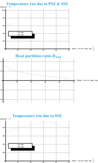
The proposition is an interesting analytical model which focuses on the temperature distribution due to both the shear zones [7]. Concerned with the tool chip interface, the model proposes to equalize temperatures on the both sides of the interface. It implicitly assumes a thermically perfect contact. Moreover this model introduces a local heat partition ratio. For instance, for the secondary shear zone, the heat flux flowing into the tool and then into the chip varies all along the tool contact length. This analysis reveals some interesting points such as a similar trend for all the curves presenting the local heat partition as a function of the position within the tool chip contact zone: the heat flowing into the tool seems to increase regard to the distance to the cutting edge, the vicinity of the cutting edge is always physically unacceptable (some authors talk about a heat sink in the vicinity of the cutting edge [5], some authors implement a local heat flux near the cutting edge).
In a first time only a global heat partition ratio is calculated in order to evaluate the mean chip-tool interface temperature. The second step is to compute local heat partition ratio B, to equalize the tool and the chip temperature at the interface. Once temperature equal on both side, the physically concistent model results is reached.
0.2 0.4 0.6 0.8 1.0 Distance from the cutting edge li lc 200 400 600 800 1000
TemperatureTemperature rise due to PSZ & SSZ°C
Chip Side Tool Side
0.2 0.4 0.6 0.8 1.0 Distance from the cutting edge li lc 0.4 0.2 0.2 0.4
Heat partition ratio BTool
0.2 0.4 0.6 0.8 1.0 Distance from the cutting edge li lc 200 400 600 800
Temperature °C Temperature rise due to SSZ
Chip Side Tool Side
Figure 1 Heat distribution examples for SSZ (0:cutting
edge, 1:contact length)
4 RESULTS AND DISCUSSION
As it has been explained, several thermal movies have been joined to obtain the full scale thermal field of the orthogonal cutting scene. From there the objective is to extract the rake face temperature distribution in order to correlate it with the simplified model. As we can see some step of the acquisition of such information, we have decided to especially extract the temperature distribution, the mean temperature, the temperature range along contact zone.
(a)
(b)
Mean temperature 506°C Maximum position 0,75 Half temperature range 64°C
(c)
Figure 2 Example of processing for experiment C ((a)
raw image, (b) reconstruction, (c) extraction)
4.1 Steady state and repeatability analyse
Orthogonal cutting is a metal cutting operation which is commonly assumed to reach a steady state. But during experiments as sample rate is high enough it is possible to observe the transient part. So, first observations have been made with a virtual probe to check temperature time evolution for a point located 0,6mm far from the cutting edge within the tool-chip contact zone. It is important to obtain a stationary operation because first the associated model is a stationary one and if such a mode is not obtain, how and when can we extract temperature distribution.
Chip
Tool
Figure 3 Temperature evolution function of cutting length
Observations are very similar from previous work [4]. A transient state is noticeable, followed by a linear increase. The evolution observed can be roughly described by a function
(5) This expression takes into account the possibility of an linear increase of the local temperature of the tool over time. One of the most important questions is related to the steady state or at least pseudo-steady state. L can be considered as a characteristic length (i.e. an estimation of the minimum cutting length to be performed). B characterizes the linear evolution of the temperature pseudo steady mode if any. If B is found small enough it will mean that the stationary assumptions can be made.
Experiment A B L
A 406 9,42E-5 24,1 B 432 1,24E-4 24,2 C 618 2,95E-5 31,1 D 485 1,07E-4 47,3
Table 3 Constant model fit values
First thing to observe is B coefficient which quantify the pseudo-stationary state, note that we have an increase around 1E-4 °C per millimeter cut. These results are encouraging because it is small but on an experiment where 1m is cut it can impact directly temperature distribution for several operating conditions. So, measure will be taken at 10.L of cutting length as L is a good indicator of the transient state length.
On the repeatability assumptions some experiments have been carried out several times in order to compare results and their dispersion. It has been proven that the most difficult is to find the cutting edge position on the film with accuracy and that is why an automatic processing of IR video files has been developed. Without this automatic calculation the operator sensitivity was too important to determine accurately the rake face as well as the tool-chip contact length. The automatic detection decreases the error down to 30 µm on the cutting edge position and even less on the rake face. For an operator error positioning the cutting edge was up to 5 times this. On the other hand the temperature distribution repeatability was pretty good since the mean error is always lower than 3%. Note that cutting and cutting force repeatability error was around 2%. So the experimental setup and processing was considered satisfying. It is first matter to have a good repeatability as at least 2
experiments must be realized in order to obtain full range cutting scene temperature as the camera needs to acquire with 2 filters position.
4.2 Mean temperature along tool chip contact length
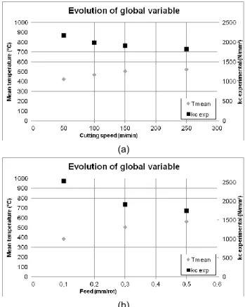
The data processing begins with an analysis of the global values: cutting forces, mean temperature. First point of interest was to compare global results that it is possible to obtain with known fact, in order to check the setup capability.
(a)
(b)
Figure 4 Mean temperature in function of cutting speed
(a) and feed (b)
We note that specific cutting force diminish with cutting speed. On the opposite cutting temperature hereby consider as the average measured temperature within the tool-chip contact zone increase with the cutting speed. Tendency are opposed which is coherent with adimensionnal approach seen [6]. Same results can be outlined for feed dependence. But ratio between minimal and maximal values is greater for cutting speed.
First, we see that the mean temperature along rake face evolve as the inverse of the specific cutting force kc. As it
is known in the literature the higher cutting temperature softens the material and allows lowering the cutting force. Mean temperature and maximal temperature along tool-chip are very restrictive. Heat flux density and material behavior in the very contact zone are not described as well as possible. Is there a switching from sticking to sliding contact if any where and when does it happen? For this issue we try to extract the whole temperature distribution at the tool-chip interface. We can see that not only mean temperature vary according to the cutting speed. For example, range and maximum position are very interesting quantity in order to identify a local heat flux distribution at the tool-chip interface.
Figure 5 Examples of temperature distributions for
several cutting speed
5 CONCLUSION AND PERSPECTIVES
Infrared thermography experiments take time to properly design and fix. The experimental setup seems viable even if precaution must be taken in order to compare several experiments on the same bases. First step was to confirm if that setup was operational through classical experiments. For that confirmation global values interpretation have been made. Cutting forces and mean temperature seems pertinent. Steadiness and repeatability have been measured and we have now a good understanding of their evolution. These measurements have highlighted the importance of automatic treatment. The next step will be to use local values as temperature distribution at the interface between the chip and the tool. And to use these results on the proposed model in order to get back to a probable heat flux on the secondary shear zone.
6 REFERENCES
[1] Astakhov, V., 2006. Tribology of metal cutting 1st éd., Elsevier
[2] Arrazola, P.J., Arriola, I. & Davies, M.A., 2009. Analysis of the influence of tool type, coatings, and machinability on the thermal fields in orthogonal machining of AISI 4140 steels. CIRP Annals-Manufacturing Technology, 58(1), p.85–88.
[3] Arrazola, P.J. et al., 2008. The effect of machinability on thermal fields in orthogonal cutting of AISI 4140 steel. CIRP Annals-Manufacturing Technology, 57(1), p.65–68.
[4] Barlier, C., Lescalier, C. & Mosian, A., 1997. Continuous Flank Wear Measurement of Turning Tools by Integrated Microthermocouple. CIRP Annals - Manufacturing Technology, 46(1), p.35-38. [5] Chao B.T., Trigger K.J., 1956, Temperature
Distribution at Tool-Chip and Tool-Work Interface in Metal Cutting, Transaction to ASME (56)
[6] Davies, M.A., Cooke, A.L. & Larsen, E.R., 2005. High Bandwidth Thermal Microscopy of Machining AISI 1045 Steel. CIRP Annals - Manufacturing Technology, 54(1), p.63-66.
[7] Komanduri, R. & Hou, Zhen B., Thermal modeling of the metal cutting process. International Journal of Mechanical Sciences
[8] Shaw, M.C., 1989, Metal cutting principles, Oxford University Press
7 AKNOWLEDGMENT
The authors would like to give a special thanks to Jeremy Bianchin, Daniel Boehm, Lionel Simon and Marc Borsenberger for their assistance in this work.