Science Arts & Métiers (SAM)
is an open access repository that collects the work of Arts et Métiers Institute of Technology researchers and makes it freely available over the web where possible.
This is an author-deposited version published in: https://sam.ensam.eu
Handle ID: .http://hdl.handle.net/10985/17279
To cite this version :
Binsdu JIA, Alexis RUSINEK, Slim BAHI, Richard BERNIER, Raphaël PESCI, Amine BENDARMA Perforation Behavior of 304 Stainless Steel Plates at Various Temperatures -Journal of Dynamic Behavior of Materials - Vol. 5, n°4, p.416-431 - 2019
Any correspondence concerning this service should be sent to the repository Administrator : archiveouverte@ensam.eu
Perforation Behavior of 304 Stainless Steel Plates at Various
Temperatures
B. Jia1,2 · A. Rusinek3,5 · S. Bahi3 · R. Bernier3 · R. Pesci2 · A. Bendarma4
Abstract
The effect of temperature on perforation behavior of 304 austenitic stainless steel plates was investigated experimentally. Perforation tests have been conducted at velocities from 80 to 180 m/s and temperatures between − 163 and 200 °C. Low temperatures were obtained using a specific designed cooling device and the temperature distribution on the specimens was verified to be uniform. Based on the experimental results, the failure mode, the initial-residual velocity curves, the ballistic limit velocities and the energy absorption capacity under different temperatures were analyzed. It was found that petalling was the main failure mode during the perforation process. The average number of petals was three at 20 °C or 200 °C and was increasing continuously to five at − 163 °C. The ballistic limit velocity Vbl was also affected by the initial temperature.
It increased slightly from 93 m/s at 200 °C to 103 m/s at − 20 °C and then remained constant at lower temperatures. The material showed better energy absorption capacity at low temperatures and this came not only from the temperature sensitiv-ity of the material but also from the strain-induced martensitic transformation effect. According to martensite measurement by X-ray diffraction technique, the martensite fractions along the fracture surface of petals were 87.1%, 66.2%, 52.8% and 32.4% respectively for initial temperatures of − 163 °C, − 60 °C, − 20 °C and 20 °C.
Keywords Perforation · Low and elevated temperatures · Failure mode · Energy absorption · Martensitic transformation
Introduction
As a representative of transformation induced plasticity (TRIP) steels [1, 2], 304 austenitic stainless steel (ASS) has high resistance to corrosion and oxidation as well as a unique combination of high strength and high ductility. Its
beneficial mechanical properties come from strain-induced martensitic transformation (SIMT), which means that upon plastic deformation the initial austenite phase ( γ ) transforms into stable martensite phase ( 𝛼′ ); thus both increased work hardening rate and significantly enhanced ductility can be achieved. These properties make 304 ASS extensively used in many areas such as civil engineering, navigation and transportation. During its working and manufacturing pro-cess such as liquid natural gas storage and transportation at low temperature [3, 4] and sheet metal forming at elevated temperatures [5, 6], it may be subjected to impact loading over a wide range of temperatures.
As impact loading is encountered from time to time in so many areas, a considerable amount of work has been done over the last decades to study the impact behavior of mate-rials [7, 8]. According to the projectile velocity, investiga-tion on impact behavior of materials can be divided into 3 categories. The first category refers to low velocity impact (< 50 m/s), where thin plates are commonly perforated by a drop weight tower [9]. The second covers sub-ordnance and ordnance velocity range between 50 and 1300 m/s, where projectiles are usually accelerated by a compressed air gas
gun to perforate or penetrate plates [7, 10, 11]. The last cat-egory refers to hypervelocity impact (> 1300 m/s), a velocity range often encountered in outer space impact such as debris hitting spacecrafts [12]. The second velocity regime aims at investigating the dynamic impact behavior of shell struc-tures in many engineering areas and therefore has received the most attention. Mostly, sub-ordnance impact tests were performed with thin plates and non-deformable projectiles at room temperature to study its ballistic resistance perfor-mance, energy absorption capacity and failure mode. Those studies mainly focus on the influence of target thickness [13], impact obliquity [14], multilayer plates combination [15] and projectile nose shape [16–18] on perforation behav-ior of materials. Børvik et al. [13] investigated perforation and penetration behavior of Weldox 460E steel plates with target thickness varying between 6 and 30 mm. The slope of the initial-residual velocity curves decreases with increasing target thickness and the target deformation mode changes from global deflection to shear localization. Rodríguez-Martínez et al. [19] found that the ballistic limit velocity of 304 ASS thin plates was affected by a combination of target thickness and projectile shape. Alavi Nia and Hoseini [15] compared ballistic resistance performance of monolithic, in-contact layered and spaced layered aluminum plates and found the monolithic target behaved the best. Børvik et al. [16, 18] conducted perforation tests of Weldox 460E steel plates using blunt, conical and hemispherical projectiles. It was found that both the energy absorption capacity and the failure mode of the material were affected by the projectile nose shape. The failure mode for the blunt projectile was shear banding while conical and hemispherical projectiles perforated the target by pushing the material aside, corre-sponding to a failure by ductile hole enlargement.
While material properties at low or elevated temperatures differ significantly from those at room temperature [20], quite a limited number of studies concerning perforation behavior of materials under various temperatures can be found. Mostly, the low temperature impact studies focus on hypervelocity impact of lightweight alloys and composites at around − 173 °C [21–24]. Also, with a specially designed drop weight tower, the low velocity impact behavior of AA 2024-T3 aluminum and TRIP 1000 steel at − 60 °C was investigated by Rodríguez-Martínez et al. [25, 26]. As for studies concerning impact behavior of materials under sub-ordnance or sub-ordnance velocity at different temperatures, high temperature perforation by several authors were found [27–30]. Rusinek et al. [27] developed a heating chamber coupled to the ballistic impact device to investigate perfora-tion behavior of poly(methyl methacrylate) (PMMA). With the thermal chamber, Klosak et al. [30] studied perforation behavior of brass alloy plates under temperatures ranging from 20 to 260 °C. Results showed that the energy absorp-tion capacity decreased with increasing temperature. There
was also some changes in the petalling failure mode: the number of petals increased from 3 to 6 within the testing temperature regime. Liu et al. [28] investigated the ballis-tic performance of GH4169 alloy at temperatures ranging from 25 to 600 °C. A similar conclusion was obtained: larger plastic deformation of specimens and lower ballistic limit velocities at higher temperature. For sub-ordnance and ord-nance velocity impact of materials under low temperatures, so far as we know, has not been investigated yet in the open literature.
According to literature review above, although 304 ASS may suffer from impact loading over a wide range of tem-peratures, the sub-ordnance and ordnance velocity impact behavior remains unclear. The purpose of this study, there-fore, is to study the effect of the initial temperature on the perforation behavior of 304 stainless steel. First, an original cooling device was developed to test the structure behavior at low temperatures, ranging from − 163 to − 20 °C. The temperature distribution along the specimen surface was measured and simulated to be sure about the uniform tem-perature distribution. Then, ballistic impact tests of 304 steel plates were carried out under temperatures from − 163 to 200 °C using the newly developed cooling device and the heating chamber by Rusinek et al. [27]. The target thickness was 1.5 mm and the projectile velocity was varying between 80 and 180 m/s. The experimental setup allowed measuring the initial velocity V0 and residual velocity VR curves of the
3D structure. In addition, martensite fraction in perforated specimens was measured by X-ray diffraction technique to explain the improved energy absorption capacity of 304 ASS at low temperatures.
Material Behavior and Apparatus
Description
Ballistic Impact Set‑up
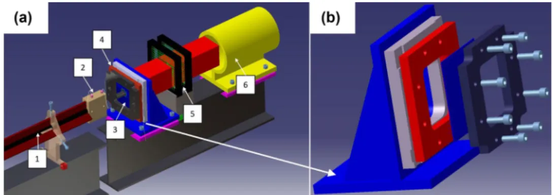
Ballistic impact tests of 304 stainless steel were performed using a pneumatic gas gun shown in Fig. 1. During the tests, the projectile is launched using a pneumatic gas gun and goes through the gas gun tube. By changing the initial pres-sure P0 , the impact velocity V0 of the projectile may change up to 180 m/s for a mass of 29 g.
A detailed description of the target fixation with holders is shown in Fig. 1b. The target is sandwiched tightly between two holders by eight screws. These holders are made of high strength steel to be sure that no plastic deformation occurs during the testing process. After the impact process, three states named no perforation, critical perforation and com-plete perforation may be observed. If a comcom-plete perfora-tion occurs, a residual velocity VR is measured by a method
similar to the one described previously. Finally, the projec-tile catcher acts as a buffer to avoid damage.
Experimental results such as target deflection, fracture pattern and energy absorption capacity of materials are all influenced by the shape and mechanical properties of the projectile. Therefore, the dimensions and the mechanical properties of the projectile and of the target are introduced in the next section.
Projectile and Target Description
The dimensions of the projectile used in this study are shown in Fig. 2. It is a cylinder with a diameter of 12.8 mm and a height of 25 mm corresponding to a mass of 29 g. At the top of the cylinder, a conical nose with an angle of 72° is machined as reported in [31]. The projectile is made of Maraging steel with a hardness of 640 HV and a yield stress of 2 GPa. The hardness and the strength are so high that the projectile is assumed to be rigid during experiments and numerical simulations.
The specimens were delivered as thin plates of 130 mm side length and 1.5 mm thickness. Their initial microstruc-ture was 100% austenite phase. They were tightly fixed by the target holder to avoid sliding.
Ballistic impact of materials under low or elevated temperatures is encountered from time to time in many
engineering areas such as liquefied natural gas (LNG) trans-portation and sheet metal forming. Hence, it is necessary and interesting to study temperature effect on the perfora-tion behavior of materials. In the next secperfora-tion, the thermal chamber for high temperature testing is introduced.
Thermal Chamber for High Temperature Perforation Tests
In order to perform perforation tests at elevated temperature (200 °C), a thermal chamber developed by Rusinek et al. [27] was adopted, Fig. 3. A furnace is used to heat up the air inside the chamber and then hot air is flowing around using a fan. By thermal conductivity and after a certain waiting time, the specimen reaches the expected temperature. Two thermocouples are fixed in the chamber: one to monitor the temperature inside the oven, another one on the center of the specimen to calibrate the temperature difference between the specimen and the air in the thermal chamber. In order to reach a uniform temperature distribution in the specimen, a waiting time of 20 min is imposed.
To cover perforation tests at not only elevated tempera-tures but also low temperatempera-tures, a cooling device for low temperature testing is developed and introduced in the next section.
A Specific Cooling Device for Low Temperature Perforation Tests
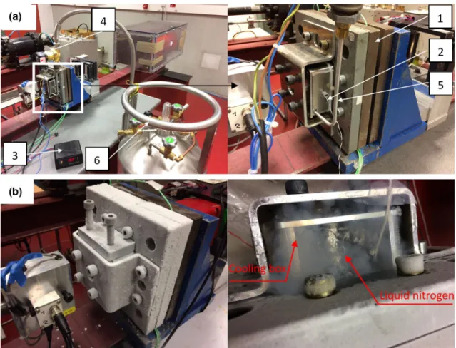
To conduct perforation tests at low temperatures, a cool-ing device has been designed and developed. As shown in Fig. 4a, the cooling box is fixed on the ballistic impact device. On one hand, the cold nitrogen gas flows from a liq-uid nitrogen tank through an aluminum pipe into the cooling box; on the other hand, the temperature inside the cooling box is monitored by a thermocouple connected to a tempera-ture controller. Once the temperatempera-ture inside the box reaches the set value, the temperature controller cuts off the power of the pump to stop the nitrogen gas flow. By this method, low temperatures between − 90 and − 20 °C can be obtained.
Fig. 1 Schematic view of the
ballistic impact device: (1) gun barrel, (2) initial velocity measurement, (3) target, (4) target holder, (5) residual veloc-ity measurement, (6) projectile catcher
In addition, by filling the cooling box with liquid nitrogen directly, − 163 °C can be obtained, Fig. 4b.
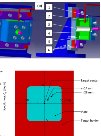
The arrangement of the cooling device on the ballistic impact device is shown in Fig. 5. The 304 ASS plate is fixed on the target holder, then the cooling box is fixed on the tar-get with a cooling box holder. The box is made of aluminum alloy to ensure a good heat transfer. In addition, four screws
are used to apply a reduced force on the cooling box surface to ensure a correct contact between the plate and the cooling box. Therefore, the cooling box and the target are in tight contact with each other during the whole testing process.
Since the cooling device for low temperature perforation tests was newly developed, its reliability should be veri-fied before testing. Unlike the device for high temperature
Fig. 3 Apparatus for high temperature perforation testing: a general view of the ballistic impact device and b schematic view of the thermal
chamber [27]
Fig. 4 Apparatus of the cooling device for testing: a between − 90 and − 20 °C and b at − 163 °C: (1) ballistic impact device, (2) thermocouple,
perforation tests where the specimen is sealed firmly in a thermal chamber and a uniform temperature distribution is obtained easily, cryogenic temperatures present an experi-mental complexity to be performed, especially in terms of stabilization at extreme low temperatures, close to − 163 °C. In addition, due to the decreasing thermal conductivity k(T) and the specific heat capacity Cp(T) under extreme low
tem-peratures Fig. 6, it is important to verify that the impacted zone is deformed in a uniform temperature environment.
Therefore, in the next section, temperature distribution on the specimen is presented and further analyzed by a FEM model based on thermal heat transfer approach.
Calibration and Heat Transfer Modeling
of the Cooling Device
To verify the reliability of the cooling device, the tempera-ture evolution and distribution in the target are measured and analyzed. First, as shown in Fig. 7, the temperature
of three radii on the target surface is measured (target center, 14 mm radius and 28 mm radius). The results are shown in Fig. 8; by setting temperatures of the coolant to be − 38 °C, − 64 °C and − 88 °C, the corresponding temperatures on the target surface are − 20 °C, − 40 °C and − 60 °C, respectively. The temperature of − 163 °C is obtained directly by filling liquid nitrogen into the cool-ing box without uscool-ing the temperature controller device. The temperatures of the three locations are not exactly the same with T14mm<Tcenter<T28mm : it is due to the hole
in the center of the cooling box, that is the path for the projectile to go through the cooling box and impact the target. Hence, the center of the target can not be cooled by surface contact with the cooling box and its temperature is slightly higher. In fact, within an area 56 mm in dimater, the maximum temperature fluctuation is only 4 °C. As the projectile diameter is only 12.8 mm, it can be assumed that the impacted zone is deformed in a uniform temperature environment.
Fig. 5 The arrangement of the
cooling device on the ballistic impact device: a isometric view and b sectional view: (1) ther-mocouple, (2) pipe, (3) target, (4) cooling box holder, (5) cool-ing box, (6) target holder
50 100 150 200 250 300 0.01 0.1 1 10 100 1000 )K· m/ W( k, yti vit cu dn oc la mr eh T Temperature, T (K) 1 10 100 1000 10000 Cp 304 ASS 6061 Aluminum Nitrogen gas
Liquid nitrogen Specific heat, Cp
(J/kg·K
)
k
Fig. 6 Thermal conductivity k and specific heat Cp of the materials
used in the numerical simulation [32]
Fig. 7 Temperature measurement positions on the target surface:
To analyze the temperature uniformity on the target in details, numerical simulation using COMSOL Multiphysics has been performed [27]. The thermal transfer is described by the generalized transient heat equation, Eq. 1.
The thermal conductivity k(T) and the specific heat Cp(T)
of the materials used in the numerical simulation are shown in Fig. 6. The two parameters are strongly depending on the temperature, especially at very low temperatures.
The boundary conditions of the simulation are defined as follow, see Eq. 2 and Fig. 9:
• Natural convective heat flux qc on the free surface of the
device.
• Forced convective heat flux qf through the inner free
sur-faces of the cooling box, due to the flow of the nitrogen gas.
• Thermal contact heat qint between different interface of
contacts in the device.
(1) 𝜌 ⋅ Cp(T) ⋅
𝜕T
𝜕t − ∇ ⋅ [k(T) ⋅ ∇T] = 0
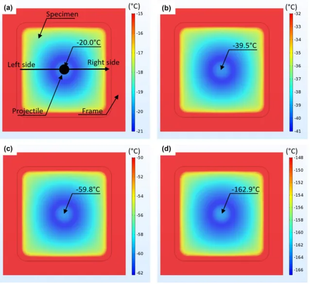
Fig. 8 Temperature distribution and evolution of the target with the coolant temperature set at: a − 38 °C, b − 63 °C, c − 87 °C and d − 183 °C
Fig. 9 Boundary conditions for temperature distribution analysis
where hc= 10 W/
(
m2⋅K) , hf = 109 W/(m2
⋅K) are the natural and forced heat convection coefficients, respectively. The conductance hint is equal to 10
5W/ (m2
⋅K).
The simulation results are shown as dots in Fig. 8. In Fig. 8a, b: the numerical results and experiments are in good agreement. In Fig. 8c, the experimental curve decreases slower than the simulated one as the flow speed of nitro-gen gas is slightly smaller. But after a certain waiting time around 500 s, the experimental values are consistent with the simulation results. In Fig. 8d, during the initial cooling stage, the experimental curve is comparatively higher. This (2) ⎧ ⎪ ⎨ ⎪ ⎩ qc= −hc � T− T0 � in 𝜕𝛺c qf = −hf � T− T0 � in 𝜕𝛺f qint= hint � T− T0 � in 𝜕𝛺int
is mainly because during experiments, it takes time to fill the cooling box with liquid nitrogen while it is assumed that the box is full of liquid nitrogen since the beginning of the simulation. In Fig. 8a–c, the temperature fluctuation caused by the temperature controller is observed. In fact, the delay of the temperature controller is set 3 °C and it causes a tem-perature fluctuation of ± 3 °C. In Fig. 8d, the target is cooled by filling the box with liquid nitrogen and the temperature fluctuation phenomenon is not observed any more.
Based on numerical simulation, it is observed that the temperature distribution on the target surface at 1200 s may be assumed as uniform in the impact zone Fig. 10. In fact, within the perforation zone, the maximum temperature dif-ferences in the four figures are 2 °C, 3 °C, 4 °C and 8 °C, respectively. For testing 304 ASS by a conical projectile, target deformation occurs mainly in the target center with a radius of 20 mm. Under this condition, the maximum
Fig. 10 Temperature distribution on target surface at 1200 s with the cooling box temperature set at: a − 38 °C, b − 63 °C, c − 87 °C and d
temperature differences are 0.3 °C, 0.4 °C, 0.6 °C and 1.4 °C, respectively. Therefore, the temperature distribution on the target surface is pretty uniform during the perforation process.
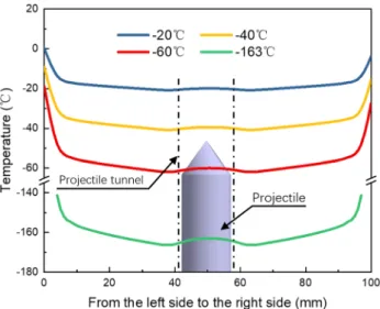
In addition, the temperature evolution from the left edge to the right edge of the target (the black line in Fig. 10a) is shown in Fig. 11. The temperature in the center of the target is slightly higher than the surrounding area, consistent with the experimental data in Fig. 8. Therefore, the simulation is in good agreement with experiments.
According to the temperature distribution analysis in this section, the temperature uniformity is obtained within the perforation area. Therefore, in the next section, perforation tests of 304 ASS under low, room and elevated temperatures are performed and the results are presented.
Influence of Testing Temperature
on the Perforation Process
In this section, perforation experiments were performed by a conical projectile for five initial temperatures: − 163 °C, − 60 °C, − 20 °C, 20 °C and 200 °C. The tests were con-ducted over a wide range of initial impact velocities, ranging from 80 to 180 m/s, to obtain a complete ballistic curve of the material. Therefore, the effect of the initial temperature on the perforation process is analyzed.
Effect of Testing Temperature on Failure Mode
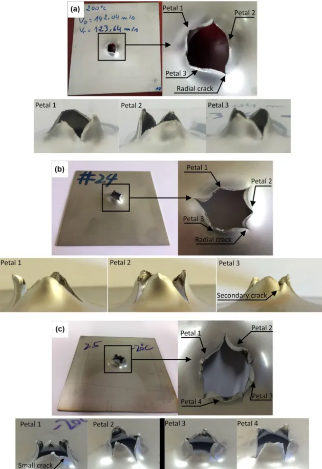
The influence of the initial temperature on the failure mode of 304 ASS is shown in Fig. 12. For the tests at 200 °C, fail-ure by ductile petalling, resulting from radial necking during the piercing process [33] is observed. A representative petal
pattern of the material at 20 °C is shown in Fig. 12b, with a number of three triangle-shaped petals form. Compared to the petals formed at 200 °C, the shape of petals at 20 °C remain unchanged but the fracture surface becomes slightly rough. In addition, several secondary cracks are observed on the bigger petals; if the crack propagates until the end of the petals, failure pattern with four petals are observed. With a further decrease in testing temperature to − 20 °C, the average number of petals increases to four and the petal shape becomes irregular. One thing should be noticed is that no debris was found for the three testing temperatures above. Concerning perforation tests at − 60 °C and − 163 °C, the breaking patterns become even rougher including debris ejection. The average number of petals increased continu-ously to five at − 163 °C, higher than that of − 20 °C, 20 °C and 200 °C. The end of the petals became pretty rugged and discontinuous. Moreover, a lot of small cracks were observed on the petal surfaces.
Except failure pattern, the ballistic curve VR− V0 and the ballistic limit velocity Vbl are also used to characterize the
ballistic impact behavior of materials. In the next section, the evolution of VR− V0 curves and that of Vbl with the testing
temperature are presented.
Effect of Testing Temperature on the Ballistic Curves VR− V0
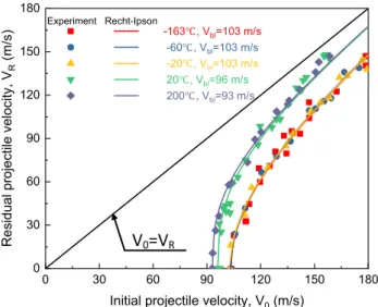
Results in terms of ballistic curves VR–V0 are presented in Fig. 13. The curves are then fitted to the relation proposed by Recht and Ipson [34], Eq. 3, in which the residual veloc-ity of the projectile is calculated as a function of the initial velocity and the ballistic limit velocity.
where V0 and VR are the initial and residual projectile
velocities, Vbl is the ballistic limit velocity and α is a fitting
parameter.
The ballistic limit velocities and fitting parameters for tests at different temperatures are given in Table 1. As shown in Fig. 13, the equation defines the ballistic curve shape properly. For testing at − 20 °C, − 60 °C and − 163 °C, the ballistic limit velocity remains the same, 130 m/s. For testing at higher temperatures, Vbl decreases with increasing
temperature. At testing temperature of 200 °C, the ballistic limit velocity is 93 m/s. While the ballistic limit velocity at 200 °C is lower than that at 20 °C, the difference between the two curves decreases with increasing impact velocity. At ballistic impact velocities higher than 150 m/s, the two curves coincide. The fitting parameter α is also affected by testing temperature: the value at room and elevated tempera-tures is obviously lower than that at lower temperatempera-tures. A
(3) VR =(V0𝛼− V
𝛼 bl
)1∕𝛼
lower 𝛼 means better impact resistance against projectile and higher ballistic limit velocity [18]. Therefore, the evolution of experimentally obtained Vbl and 𝛼 with testing
tempera-ture are consistent with each other.
Based on the ballistic curves VR− V0 , the energy absorbed by the specimens can be calculated. In the next section, the effect of testing temperature and the initial
Fig. 12 (continued) 0 30 60 90 120 150 180 0 30 60 90 120 150 180 -163 , Vbl=103 m/s -60 , Vbl=103 m/s -20 , Vbl=103 m/s 20 , Vbl=96 m/s 200 , Vbl=93 m/s V, yti col ev elit cej or pl au dis e R R (m/s )
Initial projectile velocity, V0 (m/s)
Experiment Recht-Ipson
V
0=V
RFig. 13 Ballistic curves for 1.5 mm thick plates of 304 ASS impacted
under different temperatures
Table 1 The ballistic limit
velocities Vbl and the fitting
parameter 𝛼 of 304 ASS under different testing temperatures
Testing temperature (°C) Vbl (m/s) 𝛼 − 163 103 2.006 − 60 103 2.028 − 20 103 2.005 20 96 2.712 200 93 2.660
projectile velocity V0 on the energy absorption capacity of 304 ASS is analyzed.
Effect of Testing Temperature on the Energy Absorption Capacity of 304 ASS
During the perforation process, part of the kinetic energy of the projectile is absorbed by the plate. Knowing the ini-tial projectile velocity V0 and residual projectile velocity VR , energy absorbed by the plate WTotal
Plate can be calculated
as follows:
where Mp is the mass of the projectile and equal to 29 g.
A part of the kinetic energy, Eq. 4, is transfer to the plate during the process of impact or perforation. However and as discussed in [31, 32], the energy lost due to elastic deformation of the plate, friction between the projectile and the target and those transferred to the ejected debris can be neglected. Therefore, the energy absorbed by the plate is then written as follows:
where Wh is the dissipated energy as heat, Wpb is the plastic
bending energy of the target, Wps is the plastic stretching
energy of the target, Wp is the plastic bending energy of the
petals and Wc is the crack formation and propagation energy.
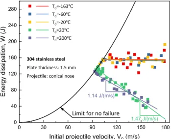
Energy absorption results as a function of V0 for tests at different temperatures are presented in Fig. 14. First, energy absorption for tests at low temperatures (− 163 °C, − 60 °C (4) WPlateTotal= 1 2Mp ( V02− V 2 R ) (5) WTotal Plate= 1 2Mp ( V2 0− V 2 R ) = Wh+ Wpb+ Wps+ Wp+ Wc
and − 20 °C) is significantly higher than at 20 °C, while energy absorption at 200 °C is the lowest. This is consistent with the fracture pattern observed: more petals and cracks at low temperatures. A similar phenomenon was observed during low velocity perforation test of TRIP 1000 steel by Rodríguez-Martínez et al. [26]: the ballistic limit velocity Vbl changed from 2.6 to 3.1 m/s when testing temperature decreased from 15 to − 60 °C. According to the analysis of Rodríguez-Martínez, the improved energy absorption at low temperature came from temperature sensitivity of the TRIP 1000 steel and no martensitic transformation was observed during the perforation process.
Another interesting phenomenon concerning energy absorption capacity of 304 ASS is the evolution of the absorbed energy with impact velocity. For the tests at low temperatures (− 163 °C, − 60 °C and − 20 °C), the initial projectile velocity V0 does not affect the absorbed energy in the tested impact velocity range. In fact, the averaged energy absorption for the three previous temperatures are 156 J, 154 J and 155 J, respectively. However, for the tests at 20 °C and 200 °C, the absorbed energy decreases linearly with increasing impact velocity. Although the absorbed energy at 20 °C is slightly higher than that at 200 °C, it decreases faster and becomes lower at impact velocities larger than 137 m/s.
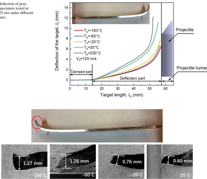
As discussed using Eq. 5, a part of the kinetic energy is induced to the plate to generate no perforation, partial or complete perforation depending on the quantity transferred to it. In order to analyze the effect of temperature on energy absorption mechanisms of 304 ASS in more details, the per-manent deflection and bending of the impacted specimens at different temperatures was measured, Fig. 15. It is clear that the target deflection increases with increasing testing temperature. Plastic bending of targets is larger at higher temperatures due to thermal softening [35]. Next, this view is further verified by petal thickness measurement.
To study the evolution of petal thickness with testing tem-perature, the perforated specimens at impact velocity around 146 m/s were cut and then the thickness of the petals was measured. As shown in Fig. 16, with increasing testing tem-perature from − 163 to 20 °C, the thickness first remains constant at around 1.26 mm and then decreases continuously to 0.60 mm (the initial plate thickness t0 was 1.5 mm). A smaller thickness at high temperatures indicates a bigger plastic strain to fracture and therefore a larger plastic defor-mation of the specimens [36].
Although the plastic deformation of specimens declines with decreasing temperature, the targets absorb more energy at lower temperatures. Therefore, it is supposed that the improved energy absorption capacity of 304 ASS at low temperatures comes from its temperature sensitivity or the SIMT effect. According to martensite fraction measurement (presented in the next section), much martensite was found
0 30 60 90 120 150 180 0 40 80 120 160 200 240 280 304 stainless steel Plate thickness: 1.5 mm Projec le: conical nose
T0=-163 T0=-60 T0=-20 T0=20 T0=200 )J( W, noit api ssi d ygr en E
Initial projectile velocity, V0 (m/s)
Limit for no failure 1.14 J/(m/s)
1.47 J/(m/s)
Fig. 14 Energy absorbed by the target as a function of the initial
in the petal area under low temperatures. Hence, differ-ent from the results of Rodríguez-Martínez et al. [26], the improved energy absorption of 304 ASS at low temperatures is related not only to the temperature sensitivity but also the SIMT effect.
X‑ray Diffraction Analysis of Specimens
Perforated at Different Temperatures
A notable phenomenon during the deformation process of 304 ASS is martensitic transformation. The transformation helps to increase not only the flow stress but also the duc-tility of the material. This phenomenon is often observed during quasi-static deformation tests of 304 ASS. However, studies concerning SIMT under impact loading are rarely
published. To verify if martensitic transformation occurs during ballistic impact tests and also to study its influence on the perforation behavior of 304 ASS, martensite fraction in post-mortem specimens was measured by X-ray diffrac-tion (XRD) technique.
Determination of Phases Volume Fraction by X‑ray Diffraction (XRD) Technique
After perforation tests, the microstructure of specimens changed from pure austenite to a combination of martensite 𝛼′ (body-centered tetragonal phase) and austenite 𝛾 (face-centered cubic phase). The volume fraction of each phase is proportional to the integrated diffraction peak intensity. Hence, using a portable PROTO goniometer and by com-paring the integrated X-ray diffraction intensities of the two
Fig. 15 Deflection of
post-mortem specimens tested at around 125 m/s under different temperatures
phases with the theoretical intensities, the volume fraction of each phase is determined by Eqs. 6–8.
where I𝛼′ and I𝛾 are the integrated diffraction peak intensities
of martensite and austenite phases, respectively. R𝛼′ and R𝛾
are parameters depending on the phase composition, crystal structure, interplanar spacing (hkl) and the Bragg angle. Two peaks for each phase were considered: {211} and {200} for martensite, {220} and {200} for austenite [37].
Effect of Testing Temperature on Martensitic Transformation of 304 ASS
Martensitic transformation occurs in 304 ASS under certain conditions, it usually affects deformation and fracture behav-ior significantly. Martensite is often observed in austenite stainless steel under quasi-static strain rate or cryogenic tem-peratures [38–41]. However, for martensitic transformation
(6) V𝛼� = I𝛼�∕R𝛼� [( I𝛼�∕R𝛼� ) +(I𝛾∕R𝛾)] (7) V𝛾 = [( I𝛾∕R𝛾 I𝛼�∕R𝛼� ) +(I𝛾∕R𝛾)] (8) V𝛼�+ V𝛾 = 1
under dynamic loading, few studies can be found [19, 42]. To investigate its influence on perforation behavior of 304 ASS, martensite distribution in perforated specimens under different temperatures was measured by X-ray diffraction technique. First, the plates impacted at around 146 m/s under − 163 °C, − 60 °C, − 20 °C and 20 °C were cut, Fig. 17. The parameter Md is the temperature above which no martensitic
transformation occurs even with large plastic deformation [43]: it is measured for our material to be 140 °C. So there is no martensite formed under perforation tests at 200 °C (hence not considered). Then, martensite fraction on the fracture surface of the petals, Fig. 17a, and along the cross-section of the plates, Fig. 17b, was measured.
Martensite fraction on the fracture surface of the petals is shown in Fig. 18a. It is clear that the martensite frac-tion decreases with increasing testing temperature. A high amount of martensite of 87.1% was found at − 163 °C and this value decreases continuously to 32.4% at 20 °C. As martensitic transformation is pretty sensitive to tempera-ture, lower transformation rate at higher temperatures is often observed in quasi-static tension or shear tests [33, 34, 44, 45].
Martensite distribution along the cross-section of the plates is shown in Fig. 18b. Transformation occurs mainly in the petals and martensite fraction in the plate deflection part is comparatively lower. With increasing temperature from − 163 to 20 °C, martensite fraction in the petal part decreases continuously but the value is almost constant in
Fig. 17 Martensite measurement positions of the perforated specimens: a on the fracture surface of the petals and b along the cross-section of
the plate deflection part. What is more, in the petal part martensite fraction decreases quickly from the top of the petal to its bottom. Compared to the martensite fraction on the fracture surface of the petals, martensite inside the pet-als is obviously lower. This is mainly because the fracture surface corresponds to the maximum plastic deformation until failure while plastic deformation inside the petals is comparatively smaller.
Conclusions and Remarks
With a newly developed cooling device for ballistic impact device, influence of the temperature on perforation behavior of thin 304 ASS plates impacted by a conical projectile in the velocity range of 80 and 180 m/s was studied. Based on experimental observations, the following conclusions are drawn:
• The cooling device helps to perform perforation tests at low temperatures ranging from − 163 to − 20 °C. Tem-perature uniformity on the plate surface is verified both experimentally and by numerical simulation. After a waiting time of 1200 s, the maximum temperature fluc-tuation on the plate surface are 2 °C, 3 °C, 4 °C and 8 °C for testing temperature − 20 °C, − 40 °C, − 60 °C and − 163 °C, respectively. If only the plate center (with a radius of 20 mm) where plate deformation mainly occurs is considered, the maximum temperature fluctuations are 0.3 °C, 0.4 °C, 0.6 °C and 1.4 °C, respectively.
• In the testing temperatures considered, petalling is the failure mode of the perforation process. The number of petals increases with decreasing testing temperature. The average number of petals is three at 20 °C or 200 °C, and
increased continuously to five at − 163 °C. The shape of the petals is also affected by the testing temperature: it looks like a regular triangle at 20 °C and 200 °C while becomes rugged and discontinuous at lower tempera-tures.
• The ballistic limit velocity Vbl is also affected by testing
temperature. It increases slightly from 93 m/s at 200 °C to 103 m/s at − 20 °C and then remains constant at even lower temperatures. Also, the ballistic curves V0− VR
are influenced by testing temperature. For 20 °C and 200 °C, the ballistic curves seem to coincide when the initial projectile velocity is much higher than the ballistic limit velocity. The ballistic curves at − 20 °C, − 60 °C and − 163 °C are almost the same and slightly lower than that at 20 °C and 200 °C.
• Although the plastic deformation of target is smaller at lower testing temperatures, the energy absorption capac-ity of 304 ASS at low temperatures is obviously higher than at room or elevated temperatures. A high amount of martensite was observed in the perforated specimens, especially in the petals. The improved energy absorption capacity of 304 ASS at low temperatures comes from not only temperature sensitivity of the material but also the SIMT effect.
Acknowledgements This work of the first author was financially
sup-ported by China Scholarship Council under Grant 201606220056. Author from Agadir thanks M. Tomasz Libura from IPPT to participate in the construction of the device allowing to reach high temperatures under dynamic impact and perforation. The system has been developed in agreement between IPPT, Universiapolis Agadir and Lorraine Uni-versity, patent no. 41383 Kingdom of Morocco (2017).
Fig. 18 Martensite fraction distribution of the perforated specimens: a on the fracture surface of the petals and b along the cross-section of the
References
1. Fischer FD, Sun Q-P, Tanaka K (1996) Transformation-induced
plasticity (TRIP). Appl Mech Rev 49:317–364. https ://doi.
org/10.1115/1.31019 30
2. Fischer FD, Reisner G, Werner E, Tanaka K, Cailletaud G, Antret-ter T (2000) A new view on transformation induced plasticity
(TRIP). Int J Plast 16:723–748. https ://doi.org/10.1016/S0749
-6419(99)00078 -9
3. Kim J-H, Choi S-W, Park D-H, Lee J-M (2015) Charpy impact properties of stainless steel weldment in liquefied natural gas pipelines: effect of low temperatures. Mater. Des (1980-2015)
65:914–922. https ://doi.org/10.1016/j.matde s.2014.09.085
4. Park WS, Chun MS, Han MS, Kim MH, Lee JM (2011) Compara-tive study on mechanical behavior of low temperature application materials for ships and offshore structures: part
I—experimen-tal investigations. Mater Sci Eng A 528:5790–5803. https ://doi.
org/10.1016/j.msea.2011.04.032
5. Jayahari L, Gangadhar J, Singh SK, Balunaik B (2017) Investiga-tion of high temperature forming of ASS 304 using BARLAT
3-parameter model. Mater Today: Proc 4:799–804. https ://doi.
org/10.1016/j.matpr .2017.01.088
6. Sun G, Du L, Hu J, Zhang B, Misra RDK (2019) On the influ-ence of deformation mechanism during cold and warm rolling on annealing behavior of a 304 stainless steel. Mater Sci Eng A
746:341–355. https ://doi.org/10.1016/j.msea.2019.01.020
7. Børvik T, Langseth M, Hopperstad OS, Malo KA (1999) Ballistic
penetration of steel plates. Int J Impact Eng 22:855–886. https ://
doi.org/10.1016/S0734 -743X(99)00011 -1
8. Rusinek A, Rodríguez-Martínez JA, Zaera R, Klepaczko JR, Arias A, Sauvelet C (2009) Experimental and numerical study on the perforation process of mild steel sheets subjected to perpendicular impact by hemispherical projectiles. Int J Impact Eng 36:565–587. https ://doi.org/10.1016/j.ijimp eng.2008.09.004
9. Antoinat L, Kubler R, Barou J-L, Viot P, Barrallier L (2015) Per-foration of aluminium alloy thin plates. Int J Impact Eng 75:255–
267. https ://doi.org/10.1016/j.ijimp eng.2014.07.017
10. Bendarma A, Jankowiak T, Łodygowski T, Rusinek A, Klósak M (2017) Experimental and numerical analysis of the aluminum alloy AW5005 behavior subjected to tension and perforation under
dynamic loading. J Theor Appl Mech 55:1219–1233. https ://doi.
org/10.15632 /jtam-pl.55.4.1219
11. Rodríguez-Millán M, Vaz-Romero A, Rusinek A, Rodríguez-Mar-tínez JA, Arias A (2014) Experimental study on the perforation process of 5754-H111 and 6082-T6 aluminium plates subjected to normal impact by conical hemispherical and blunt projectiles. Exp
Mech 54:729–742. https ://doi.org/10.1007/s1134 0-013-9829-z
12. Numata D, Ohtani K, Anyoji M, Takayama K, Togami K, Sun M (2008) HVI tests on CFRP laminates at low temperature.
Int J Impact Eng 35:1695–1701. https ://doi.org/10.1016/j.ijimp
eng.2008.07.055
13. Børvik T, Hopperstad OS, Langseth M, Malo KA (2003) Effect of target thickness in blunt projectile penetration of Weldox 460 E
steel plates. Int J Impact Eng 28:413–464. https ://doi.org/10.1016/
S0734 -743X(02)00072 -6
14. Goldsmith W, Finnegan SA (1986) Normal and oblique impact of cylindro-conical and cylindrical projectiles on metallic
plates. Int J Impact Eng 4:83–105. https
://doi.org/10.1016/0734-743X(86)90010 -2
15. Alavi Nia A, Hoseini GR (2011) Experimental study of perfo-ration of multi-layered targets by hemispherical-nosed
projec-tiles. Mater Des 32:1057–1065. https ://doi.org/10.1016/j.matde
s.2010.07.001
16. Børvik T, Hopperstad OS, Berstad T, Langseth M (2002) Perfora-tion of 12 mm thick steel plates by 20 mm diameter projectiles with flat, hemispherical and conical noses: part II: numerical
simulations. Int J Impact Eng 27:37–64. https ://doi.org/10.1016/
S0734 -743X(01)00035 -5
17. Arias A, Rodríguez-Martínez JA, Rusinek A (2008) Numerical simulations of impact behaviour of thin steel plates subjected to cylindrical, conical and hemispherical non-deformable projectiles.
Eng Fract Mech 75:1635–1656. https ://doi.org/10.1016/j.engfr
acmec h.2007.06.005
18. Børvik T, Langseth M, Hopperstad OS, Malo KA (2002) Perfora-tion of 12 mm thick steel plates by 20 mm diameter projectiles with flat, hemispherical and conical noses: part I: experimental
study. Int J Impact Eng 27:19–35. https ://doi.org/10.1016/S0734
-743X(01)00034 -3
19. Rodríguez-Martínez JA, Rusinek A, Pesci R, Zaera R (2013) Experimental and numerical analysis of the martensitic transfor-mation in AISI 304 steel sheets subjected to perforation by coni-cal and hemisphericoni-cal projectiles. Int J Solids Struct 50:339–351. https ://doi.org/10.1016/j.ijsol str.2012.09.019
20. Rusinek A, Rodriguez-Martinez JA, Pesci R, Capelle J (2010) Experimental characterisation and modelling of the thermo-vis-coplastic behaviour of steel AISI 304 within wide ranges of strain rate at room temperature. J Theor Appl Mech 48(4):1027–1042 21. Ohtani K, Numata D, Kikuchi T, Sun M, Takayama K, Togami
K (2006) A study of hypervelocity impact on cryogenic
materi-als. Int J Impact Eng 33:555–565. https ://doi.org/10.1016/j.ijimp
eng.2006.09.025
22. Tanaka K, Nishida M, Takada N (2006) High-speed penetration of a projectile into aluminum alloys at low temperatures. Int J Impact
Eng 33:788–798. https ://doi.org/10.1016/j.ijimp eng.2006.09.089
23. Numata D, Ohtani K, Anyoji M, Takayama K, Sun M (2008) Experimental study of hypervelocity impacts at low
tempera-tures. Shock Waves 18:169–183. https ://doi.org/10.1007/s0019
3-008-0156-8
24. Tanaka K, Nishida M, Ogawa H, Akahori M, Aikawa F (2008) Hypervelocity crater formation in aluminum alloys at low
temper-atures. Int J Impact Eng 35:1821–1826. https ://doi.org/10.1016/j.
ijimp eng.2008.07.043
25. Rodríguez-Martínez JA, Rusinek A, Arias A (2011) Thermo-viscoplastic behaviour of 2024-T3 aluminium sheets subjected to low velocity perforation at different temperatures. Thin-Walled
Struct 49:819–832. https ://doi.org/10.1016/j.tws.2011.02.007
26. Rodríguez-Martínez JA, Pesci R, Rusinek A, Arias A, Zaera R, Pedroche DA (2010) Thermo-mechanical behaviour of TRIP 1000 steel sheets subjected to low velocity perforation by conical projectiles at different temperatures. Int J Solids Struct 47:1268–
1284. https ://doi.org/10.1016/j.ijsol str.2010.01.013
27. Rusinek A, Bernier R, Boumbimba RM, Klosak M, Jankowiak T, Voyiadjis GZ (2018) New devices to capture the temperature effect under dynamic compression and impact perforation of
polymers, application to PMMA. Polym Test 65:1–9. https ://doi.
org/10.1016/j.polym ertes ting.2017.10.015
28. Liu J, Zheng B, Zhang K, Yang B, Yu X (2019) Ballistic perfor-mance and energy absorption characteristics of thin nickel-based alloy plates at elevated temperatures. Int J Impact Eng 126:160–
171. https ://doi.org/10.1016/j.ijimp eng.2018.12.012
29. Erice B, Gálvez F, Cendón DA, Sánchez-Gálvez V, Børvik T (2011) An experimental and numerical study of ballistic impacts on a turbine casing material at varying temperatures. J Appl Mech
78:051019. https ://doi.org/10.1115/1.40042 96
30. Klosak M, Rusinek A, Bendarma A, Jankowiak T, Lodygowski T, Klosak M et al (2018) Experimental study of brass proper-ties through perforation tests using a thermal chamber for
elevated temperatures. Latin Am J Solids Struct. https ://doi. org/10.1590/1679-78254 346
31. Rodriguez-Millan M, Garcia-Gonzalez D, Rusinek A, Abed F, Arias A (2018) Perforation mechanics of 2024 aluminium tective plates subjected to impact by different nose shapes of
pro-jectiles. Thin-Walled Struct 123:1–10. https ://doi.org/10.1016/j.
tws.2017.11.004
32. Duthil P (2015) Material properties at low temperature. arXiv :15010 7100 [Cond-Mat, Physics: Physics]. https ://doi. org/10.5170/cern-2014-005.77
33. Jankowiak T, Rusinek A, Wood P (2013) A numerical analysis of the dynamic behaviour of sheet steel perforated by a conical pro-jectile under ballistic conditions. Finite Elem Anal Des 65:39–49. https ://doi.org/10.1016/j.finel .2012.10.007
34. Recht RF, Ipson TW (1963) Ballistic perforation dynamics. J Appl
Mech 30:384–390. https ://doi.org/10.1115/1.36365 66
35. Pérez-Castellanos J-L, Rusinek A (2012) Temperature increase associated with plastic deformation under dynamic compression: application to aluminium alloy Al 6082. J Theor Appl Mech 50:377–398
36. Park WS, Yoo SW, Kim MH, Lee JM (2010) Strain-rate effects on the mechanical behavior of the AISI 300 series of austenitic stainless steel under cryogenic environments. Mater Des 31:3630–
3640. https ://doi.org/10.1016/j.matde s.2010.02.041
37. Standard A (2008) E975-03: standard practice for X-ray deter-mination of retained austenite in steel with near random crystal-lographic orientation. ASTM, West Conshohocken
38. Beese AM, Mohr D (2011) Effect of stress triaxiality and Lode angle on the kinetics of strain-induced
austenite-to-mar-tensite transformation. Acta Mater 59:2589–2600. https ://doi.
org/10.1016/j.actam at.2010.12.040
39. Byun TS, Hashimoto N, Farrell K (2004) Temperature depend-ence of strain hardening and plastic instability behaviors in
austenitic stainless steels. Acta Mater 52:3889–3899. https ://doi.
org/10.1016/j.actam at.2004.05.003
40. Talonen J, Hänninen H (2007) Formation of shear bands and strain-induced martensite during plastic deformation of
metasta-ble austenitic stainless steels. Acta Mater 55:6108–6118. https ://
doi.org/10.1016/j.actam at.2007.07.015
41. Hamada AS, Karjalainen LP, Misra RDK, Talonen J (2013) Con-tribution of deformation mechanisms to strength and ductility in two Cr–Mn grade austenitic stainless steels. Mater Sci Eng A
559:336–344. https ://doi.org/10.1016/j.msea.2012.08.108
42. Zaera R, Rodríguez-Martínez JA, Casado A, Fernández-Sáez J, Rusinek A, Pesci R (2012) A constitutive model for analyz-ing martensite formation in austenitic steels deformanalyz-ing at high
strain rates. Int J Plast 29:77–101. https ://doi.org/10.1016/j.ijpla
s.2011.08.003
43. Rodríguez-Martínez JA, Rusinek A, Pesci R (2010) Experimen-tal survey on the behaviour of AISI 304 steel sheets subjected
to perforation. Thin-Walled Struct 48:966–978. https ://doi.
org/10.1016/j.tws.2010.07.005
44. Nazeer MM, Khan MA, Naeem A, Haq A (2000) Analysis of conical tool perforation of ductile metal sheets. Int J Mech Sci
42:1391–1403. https ://doi.org/10.1016/S0020 -7403(99)00065 -X
45. Kpenyigba KM, Jankowiak T, Rusinek A, Pesci R (2013) Influ-ence of projectile shape on dynamic behavior of steel sheet sub-jected to impact and perforation. Thin-Walled Struct 65:93–104. https ://doi.org/10.1016/j.tws.2013.01.003