Science Arts & Métiers (SAM)
is an open access repository that collects the work of Arts et Métiers Institute of
Technology researchers and makes it freely available over the web where possible.
This is an author-deposited version published in: https://sam.ensam.eu Handle ID: .http://hdl.handle.net/10985/10255
To cite this version :
Fatiha CHABI, Stéphane CHAMPMARTIN, Christophe SARRAF, Ricardo NOGUERA, Blandine MAUREL Comparison of various hemodynamic models for applications to CFD in stent arteries In: XIX International Conference on Mechanics in Medicine and Biology, Italie, 201409
-Conference on Mechanics in Medicine and Biology - 2014
Any correspondence concerning this service should be sent to the repository Administrator : archiveouverte@ensam.eu
COMPARISON OF VARIOUS HEMODYNAMIC MODELS FOR APPLICATIONS TO CFD IN STENTED ARTERIES
F. CHABIa,*, S.CHAMPMARTINb, C. SARRAFa, R. NOGUERAa, B. MAURELc
aENSAM, Arts et MŽtiers, ParisTech, 151 boulevard dÕHopital, Paris, 75013, France bLAMPA, Arts et MŽtiers, ParisTech dÕAngers, 2 boulevard du Ronceray, Angers, 49035, France
c
CHRU Lille,Vascular Surgery , H™pital Cardiologique, Lille, 59037, France
This work assesses three hemodynamic models for the numerical modeling of intra-stent flows. These are the classical Poiseuille model (PM), the simplified pulsatile model (SPM) and the complete pulsatile model (CPM) based on the analysis of Womersley. They are applied to the physiological flow rate of a stented left coronary artery. The CFD package ÒAnsys Fluent 14.5Ó is used to compute the main features of the flows. The results show large differences between the steady and unsteady models notably for the wall shear stress and the re-circulation lengths, which are known to promote intra-stent restenosis. The PM is obviously not pertinent to calculate the flows involved in intra-stent restenosis. The CPM and SPM give close results but the latter model is by far less time-demanding and should be preferred.
Keywords: pulsatile physiologic flow; intra-stent flow; restenosis.
1. Introduction
According to the World Health Organization, 29% of the 56 million deaths worldwide in 2001 could be attributed to cardiovascular diseases. They are often due to a decrease of the diameter of the arterial lumen called stenosis. Available therapeutic means are based on drug delivery or surgery. Nowadays, stent implants are the most widely used angioplasty procedures for cardiovascular diseases. The first implants were bare metal stents, which gave up to 20-30% failure rates (in-stent restenosis) 1. Consecutively, drug-eluting stents were designed in the 2000s and gave good results against restenosis despite a significant additional cost. Intra-stent restenosis is a multifactorial problem. Besides human factors, it depends on the manner cardiologists implement the stents, its design and the drug used. It is also strongly coupled to the blood flow dynamics around the stent struts. Thus it is essential to characterize the features of the in-stent blood flows. In most analytical and numerical approaches found in literature, the blood flow is modeled as a steady Poiseuille flow2, or as a Poiseuille flow whose mean velocity is unsteady3. This work presents a comparison of these simplified models with a more complete pulsatile model based of the analysis of Womersley4.
2. Hemodynamic models
In this work, we assume that the blood behaves as a Newtonian incompessible fluid and the vascular wall is not deformable and impermeable. For the physiological flow under consideration here, the blood flow is laminar. The seminal model for the steady laminar flow of a Newtonian incompressible fluid (dynamic viscosity!!, density!!) in a pipe of radius ! is the Poiseuille profile:
! ! ! !! ! !!!
!! ! (1)
where ! is the average blood flow velocity and ! is the radial coordinate. This model (PM) is by far the most used model in the previous studies because of its simplicity but evidently it cannot account for the
pulsatility of real flows. To overcome this problem, many authors utilize a simplified pulsatile model (SPM) based on the previous one:
! !! ! ! !!!!! ! !!!
!! . (2)
where !!!!!is the unsteady average blood flow velocity. The main criticism to this model is that it misrepresents the profiles when the pulsatile effects are important. The complete resolution of the pulsatile flow (pulsation!!) in a tube of circular and constant cross section was provided by Womerlsey4 in 1955 and Atabek in 196155. ! !! ! !!!!! !! ! ! !! !! ! ! !! !"#$!! ! !! !! !!!! ! !! !! !!! !! !"#$ ! !!! . (3)
where !! is the Bessel function of the first kind of zero order, !!! !!! !!! is the complex amplitude of the nth harmonics of the pressure gradient, ! is the real part of a complex number and !!! ! !"#!! the generalized Womersley number.
3. Application to the case of flow in a left coronary artery
We applied these models to the case of a left coronary artery with diameter!!! ! !!!!!!. The dynamic viscosity of the blood is ! ! !!!"!!"#! ! and its density!! ! !"#"!!"!!!
. The average velocity !!!! in such a vessel is shown in Fig.1 and is reproduced from the thesis work of BŽnard6 (the period of this waveform is!! ! !!!!!).!
Figure 1: mean velocity in the left coronary artery (Ref. 6).
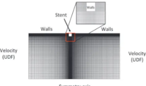
For the PM, the mean temporal value of this signal is used for ! in Eq.1. For the SPM, !!!! in Fig.1 is used directly to compute the velocity profile in Eq.2. Finally, for the CPM, the decomposition in Fourier series of !!!! is performed and processed to give the coefficients !!!and!!! in Eq.3. As a first step, we study the flow past a single stent strut with a square cross section of side ! ! !""!!!. The computational domain reduces to the 2D axisymmetric surface shown in Fig.2 below. The size of the computational domain was set to 4 mm upstream and 6 mm downstream of the strut, thereby allowing properly calculating the re-circulation zones around the stent. A structured mesh with variable grid size for a local mesh refinement at the stent is used. The boundary conditions of the three models domain were imposed by User Defined Function programmed in C language. For the unsteady models, the time step is set to !! ! !!!!!!
Figure 2: Computation domain of the stented artery.
4. Results and discussion
The flow around the stent is characterized by re-circulation zones upstream and downstream of the strut (Fig.3, left). Inside these re-circulations, very low velocities are observed and are responsible for very low values of the wall shear stresses (Fig.3, right).
Fig.3: Streamlines (left) and wall shear stress (right) in intra-stent flow.
Let !! and !! be the re-circulations lengths in the proximal and distal zones. Fig.4 shows !! and !! for the three hemodynamic models. On the average, they scale like the stent size ! ( !!! !!!! and !!! !!!!).!!! is approximately twice as small as !!. Comparing the SPM and the CPM reveals little differences (at most 3%). This suggests that the SPM is sufficient to calculate the lengths of re-circulation.
Figure 4: re-circulation lengths upstream and downstream of the stent as a function of time.
The PM is however inaccurate with deviations up to 18% for both !! and !!. These re-circulation lengths also have a direct impact on the values of the wall shear stress which is plotted in Fig. 5 as a function of time. It is measured at a distance !!!! from the stent strut in the proximal and distal regions and normalized by the steady-state value. We see again that both unsteady approaches are similar. The
difference in the distal region is at most 13%, and occurs at ! ! !!!! (diastolic minimum). The maximum difference between the SPM and CPM for the proximal stress is lower (about 8%) and still occurs at ! ! !!!!. The PM is again clearly insufficient. The stress that it gives is particularly inaccurate at the diastolic and systolic optima (maximum difference of 120% for the distal region). The SPM is again accurate enough for the determination of the wall shear stress in this configuration. Let us finally note that the computational time is roughly 6 times longer for the CPM compared to the SPM.
Figure 5: Comparison of wall shear stresses of three models. Distal region (left) and proximal region (right).
5. Conclusion
This work shows that the Poiseuille flow model is insufficient to compute both the re-circulation lengths and the wall shear stress, two of the main causes involved in in-stent restenosis. The SPM and the CPM give quite close results except at times where the peaks of the flow rate occur but the discrepancies are weak (around 10%). Considering the computational times in both unsteady cases, we recommend the use of the SPM for future numerical studies of stented arteries.
6. References
1. Wentzel JJ, krams R, Schuurbiers JCH, Oamen Ja, Kloet J, van der Giessen WJ, Slager CJ, Relationship between neointimal thickness and shear stress after wall stent implantation in human coronary arteries, Circulation 103: 1740-1745, 2001.
2. Barakat AI, Tina Cheng E, Numerical simulation of fluid mechanical disturbance induced by intravascular stents, Proceedings of ICMMB-11, International Conference on Mechanics in Medicine and Biology, 2000.
3. O'Brien CC, Kolachalama VB, Barber TJ, Simmons A, Edelman ER, Impact of flow pulsatility on arterial drug distribution in stent-based therapy, Journal of Controlled Release 186: 115-124, 2013.
4. Womersley JR, Method for the calculation of velocity, rate of flow and viscous drag in arteries when the pressure gradient is known, Journal of Physiology 127: 553-563, 1955.
5. Bulent A, Chieh CC, Oscillatory flow near the entry of a circular tube, Zeitschrift fŸr angewandte Mathematik und Physik 12: 185-201, 1961.
6. BŽnard N, Analyse de lÕŽcoulement physiologique dans un stent coronarien: Application ˆ la caractŽrisation des zones de restŽnose pariŽtale, Ph. D. Thesis, France, 2005.