This is an author-deposited version published in:
http://oatao.univ-toulouse.fr/
Eprints ID: 10189
To link to this article: DOI: 10.1109/JLT.2013.2245304
URL:
http://dx.doi.org/10.1109/JLT.2013.2245304
To cite this version:
Girard, S. and Mescia, L. and Vivona, M. and Laurent, A. and
Ouerdane, Y. and Marcandella, C. and Prudenzano, F. and Boukenter, A. and Robin, T.
and Paillet, P. and Goiffon, V. and Gaillardin, M. and Cadier, B. and Pinsard, E. and
Cannas, M. and Boscaino, R. Design of Radiation-Hardened Rare-Earth Doped
Amplifiers Through a Coupled Experiment/Simulation Approach. (2013) Journal of
Lightwave Technology (JLT), vol. 31 (n° 8). pp. 1247-1254. ISSN 0733-8724
O
pen
A
rchive
T
oulouse
A
rchive
O
uverte (
OATAO
)
OATAO is an open access repository that collects the work of Toulouse researchers and
makes it freely available over the web where possible.
Any correspondence concerning this service should be sent to the repository
administrator:
[email protected]
Design of Radiation-Hardened Rare-Earth
Doped Amplifiers through a Coupled
Experiment/Simulation Approach
S. Girard, Senior Member, IEEE, L. Mescia, M. Vivona, A. Laurent, Y. Ouerdane, C. Marcandella,
F. Prudenzano, A. Boukenter, T. Robin, P. Paillet, Senior Member, IEEE, V. Goiffon, Member, IEEE
M. Gaillardin, Member, IEEE, B. Cadier, E. Pinsard, M. Cannas, and R. Boscaino
.
Abstract— We present an approach coupling a limited
experimental number of tests with numerical simulations regarding the design of radiation-hardened (RH) rare earth (RE)-doped fiber amplifiers. Radiation tests are done on RE-doped fiber samples in order to measure and assess the values of the principal input parameters requested by the simulation tool based on particle swarm optimization (PSO) approach. The proposed simulation procedure is validated by comparing the calculation results with the measured degradations of two amplifiers made with standard and RH RE-doped optical fibers, respectively. After validation, the numerical code is used to theoretically investigate the influence of some amplifier design parameters on its sensitivity to radiations. Simulations show that the RE-doped fiber length used in the amplifier needs to be adjusted to optimize the amplifier performance over the whole space mission profile rather than to obtain the maximal amplification efficiency before its integration in the harsh environment. By combining this coupled approach with the newly-developed RH RE-doped fibers, fiber-based amplifiers nearly insensitive to space environment may be designed in the future.
Index Terms—Radiation Effects, Optical Fibers, Rare-Earth
ions, Amplifiers, Particle Swarm Optimization, Erbium, Ytterbium.
I. INTRODUCTION
ADIATION responses of Rare-Earth (RE) doped optical fibers are widely studied since these components are key elements of fiber-based systems such as amplifiers or lasers with high power capabilities. Such active fibers were also shown to be the most sensitive part of these systems to radiations [1-3]. As a consequence and despite the short length used for space applications (typically 10 to 30 meters for an Interferometric Fiber-Optic Gyroscope (IFOG) superluminescent source), the estimation
.
S. Girard, M. Vivona, A. Boukenter, Y. Ouerdane are with Université de Saint-Etienne, Laboratoire Hubert Curien, UMR CNRS 5516, F42000 Saint-Etienne, France. ([email protected]).
L. Mescia and F. Prudenzano are with Dipartimento di Ingegneria Elettrica e dell’Informazione (DIEI), Politecnico di Bari, I-70125 Bari, Italy. A. Laurent, T. Robin, B. Cadier, E. Pinsard are with IXFiber SAS, F-22300 Lannion, France.
C. Marcandella, P. Paillet and M. Gaillardin are with CEA, DAM, DIF, F91297 Arpajon France
V. Goiffon is with Université de Toulouse, ISAE, F-31055 Toulouse, France.
M. Cannas and R. Boscaino are with Dipartimento di Scienze Fisiche ed Astronomiche dell’Università di Palermo, I-90123, Italy.
of their vulnerability to the radiation constraints associated with space missions remains a crucial issue to investigate [4-5]. Mostly, these fibers have been characterized in a passive configuration (without pumping of the active ions involved) providing evidence for high radiation-induced attenuation (RIA) levels in the [600 – 900 nm] wavelength range corresponding to the absorption and emission spectral domain of RE ions [1,7]. For the RE-doped fibers containing aluminum (Al) or phosphorus (P), the point defects at the origin of their optical degradation seem related to these dopants rather than to RE ions [1,8]. As a consequence, codoping an Er-doped glass with Yb3+ ions did not increase its radiation sensitivity [8] while it optimizes its amplification efficiency. As result, Er/Yb-codoped fibers rather than Er-doped ones should be considered to design the most radiation tolerant amplifiers. A limited number of studies concerning the responses of optically pumped RE-doped fibers and amplifiers [9-13], i.e. in active configuration, was proposed in literature. M. Alam et al. [12] and. Jin Ma et al. [13] observed a complete darkening of the output power of their Er/Yb amplifiers after an irradiation dose of few dozens of krad. More recently, our group demonstrated the efficiency of Cerium-codoping in the core of Er/Yb doped optical fibers to improve their radiation tolerance [14-15], such Ce-positive effect was also observed on fibers solely doped with Yb or Er [16,17]. This radiation hardening by component approach leads to an amplifier with identical optical characteristics, before irradiation, to the ones designed with a standard RE-fiber (gain of 19 dB) but associated with a very limited radiation-induced gain decrease of ~1.5 dB after a dose of ~90 krad. This work [14] demonstrated the efficiency of a hardening by component approach of RE-doped fibers for space applications, as it was reported in [18] for Er-doped fibers. In this paper, we focused on the development of a new hardening-by-design approach that can, in complement to the hardening-by-component approach, increase even more the radiation tolerance of the fiber based amplifier. Due to the multiplicity of the amplifier design parameters and to the complexity and costs of radiation tests, such systematic study has to be based on a simulation procedure. For this reason, we built a homemade computer code based on particle swarm optimization (PSO) approach [19] and rate equations model allowing i) the recovering of some spectroscopic parameters of active ions inside the fiber, ii) the prediction of the amplifier performance before, during
2 and after irradiation. In particular, we demonstrate the ability of this numerical code to correctly simulate the changes in the amplifier characteristics due to the harsh environment, having as input parameters, only a limited set of offline RIA measurements performed on the RE-doped fiber used in the system. After its validation, we used the code to predict the general trends that are associated with changes in the design of optical amplifiers, showing that amplifiers virtually insensitive to space radiations can be obtained in the future.
II. EXPERIMENT/SIMULATION PROCEDURE
A. Tested Optical Fibers and Amplifiers
We considered the two prototype fibers of [14] with similar concentrations of the two rare earths ions (Er and Yb) in their phosphosilicate cores. These two samples, named STD and RH respectively have bare fiber geometry with an octagonal pure-silica double-clad (DC) as illustrated in the inset of Fig.1. The main difference is the addition of Cerium (Ce) ions in the core of RH sample that strongly enhances its radiation tolerance [14], [15], [20]. Fig.1 illustrates the attenuation spectra of both fibers before irradiation. Using the cut back technique we performed the absorption spectra and the corresponding bands are located around 915 nm for the Yb3+ ions, 1480 nm and 980 nm for Er3+ ions. Based on the same length (12 m) of the two fibers, we designed two amplifiers (A-STD and A-RH, respectively) with the same 19 dB gain for a 10 dBm input power. A backward pumping scheme is used in which the 915 nm laser pump and the 1545 nm signal to be amplified propagate in opposite directions [21].
Fig. 1. Background attenuation measured by the cut-back method in fibers STD and RH through excitation of the double clad with a white light source. The inset illustrates a picture of RH fiber. B. Radiation Tests
The necessary experimental results for the PSO simulations were acquired thanks to an irradiation campaign performed with a gamma source at Université Catholique de Louvain in Belgium. During these tests, different samples of the two STD and RH fibers have been irradiated at different doses from 7 to 70 krad (~ 0.3 rad/s) without online monitoring of the fiber response during irradiation. Offline measurements of the RIA were conducted , by the cut-back technique, to
characterize the radiation effects around the pump and emission wavelengths. These extracted RIA values cannot be obtained during the online amplifier testing configuration as in [14]. They remain mandatory input parameters for the PSO calculations and the validation of the model. As we checked that the amplifiers exhibit no recovery of their properties (gain, noise figure…) around the emission and absorption wavelengths after irradiation, such offline analyses are efficient to reveal the changes induced in the fiber-based amplifiers during irradiation.
C. Fiber and Amplifier Simulations
At the best of our knowledge, except the work done by G.M Williams et al. [5] for Er-doped amplifiers no simulation study was performed to improve the radiation resistance of fiber-based amplifiers. However, several existing models reproduce the mechanisms leading to the infrared signal amplification in RE-doped optical fibers in absence of radiations. These models optimize the performance of amplifiers in terms of gain and noise figure [22,23] and are based on the identification of the optimal amplifier design parameters such as the active fiber length, pumping scheme, RE concentration, refractive-index profile, geometrical parameters of the fiber transversal section [24].
Fig. 2. Transverse electric field profiles of the normalized HE11
guided mode at the wavelength λs = 1545 nm for the fiber RH.
A computer code that solves the general evolution equations describing the longitudinal propagation of pump, signal, forward and backward amplified spontaneous emission (ASE) in diversely doped RE optical fibers has been developed at Politecnico di Bari [23,25,26]. Modeling the amplifier behavior involves different simulation steps. The first one determines, by using a full-vector finite element method (FEM) based-code, the spatial distribution of the fundamental guided mode corresponding to the 1545 nm transmitted signal to be amplified. This is achieved by considering the specific structure and composition features of both STD and RH fibers like their refractive index profiles, numerical apertures, core and inner cladding sizes. Figure 2 depicts the modulus of the normalized HE11 electric
field for the fundamental mode at λs=1545 nm evaluated by
considering the RH fiber’s parameters.
800 1000 1200 1400 1600 0.0 0.5 1.0 1.5 2.0
A
tt
e
n
u
a
ti
o
n
(
d
B
/m
)
Wavelength (nm)
Fiber RH Fiber STDA particle swarm optimization approach [27] is then used to recover the main parameters of RE-doped amplifiers. PSO is an evolutionary optimization technique inspired by the social behavior, movement and intelligence of animals moving in large groups [27], [28]. This technique can be applied to perform a global search of parameters in a multidimensional search space. In particular, the search is carried out by means of swarm agents which can dynamically adjust their trajectory according to the own experience (particle best) and the collective experience (global best) of the entire swarm. Both the particle and global best locations are derived according to the fitness function which is engineered by considering the problem constrains. A comprehensive description of this calculation method is given in [27]. Compared to other evolutionary techniques, PSO avoids the use of complicated evolutionary operators, is easy to implement, and is characterized by a reduced set of adjustable parameters. The considered fibers are doped with different amounts of the Er3+ and Yb3+ active ions that permit the signal amplification. The modeling of the amplifier takes into account the dynamics of the ion populations associated with their different energy levels under the influence of the injected pump and the signal to be amplified.
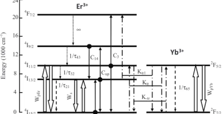
Fig. 3. Energy level transitions of the Er3+-Yb3+ system considered
in our calculations.
Fig. 3 shows the spontaneous decays (dash arrows), nonradiative decays (dot arrows), pump absorption and stimulated emission at both pump and signal wavelength (big arrows), energy transfer processes between Er3+ ions (full arrows) and between Er3+ and Yb3+ ions (dash-dot arrows) considered in the home-made computer code. Pump energy at p=915 nm is mainly absorbed by the Yb3+ ions
which are in the 2F7/2 ground level and excited to the 2F5/2
level. Excited Yb3+ ions transfer their energy to the nearby ground level Er3+ ions which are caused to transit to the 4I11/2
level. The Er3+ ions in the 4I11/2 level rapidly relax, by a non
radiative decay, to the 4I13/2 metastable level and this
facilitates the population inversion phenomenon. The transition 4I13/2→4I15/2, close to the signal wavelength s=1545 nm, allows the amplifier gain via the stimulated
emission. Unfortunately, two excited erbium ions on the
4
I13/2 level can exchange their energy: one ion returning in
the erbium ground state, by a non radiative transition, while the other raising to the 4I9/2 excited level. A similar
phenomenon occurs between two ions of the 4I11/2 level, the
former results in 4F7/2 level and the latter returns to the
ground state. In addition, we consider also the secondary energy transfer phenomenon from Yb3+ ions in the level 2F5/2
to the Er3+ ions in the 4I13/2, and the Er 3+
ions clustering effects.
III. VALIDATION OF THE SIMULATION PROCEDURE BY
COMPARISON WITH EXPERIMENTAL DATA
A. Validation of the Calculation Code without Radiation Effects
Some of the input parameters necessary for our calculations have been extracted from offline measurements made on STD and RH fiber samples. Other ones have been recovered by means of the PSO approach (eg. the lifetimes, energy transfer coefficients Ktr and Ktr1, up-conversion coefficients
Cup and C3). The erbium absorption cross sections have
been evaluated directly from the spectral attenuation measurements performed on STD and RH fiber samples before irradiation, through excitation of the fiber core, according to the relation [24]:
Eq(1) where attEr
( )
λ is the measured erbium spectral attenuation expressed in dB/m, NEr is the erbium ion concentration inthe sample (ions/m3), Γs is the overlap factor between the
propagated mode and the erbium ion distribution defined as:
Eq(2)
where D is the core diameter and E(r,φ) is the normalized transverse electric field envelope so that the surface integral of |E|2 is equal to one. The ytterbium absorption cross sections have been calculated by using an equation similar to eq. (1):
Eq(3)
where Score and Sclad are the core and cladding areas,
respectively. The two different expressions calculating
and take into account the different core and DC
pumping schemes for Er3+ and Yb3+ absorption cross sections, respectively. Tested amplifiers, A-STD and A-RH have been designed in a backward pumping scheme [14]. The erbium emission cross sections have been calculated by using the McCumber theory [24]:
Eq(4)
where
E
ZLis the energy difference between the bottom ofthe 4I13/2manifold and the bottom of the ground state 4I15/2
,
Tis the temperature and κ is the Boltzmann’s constant. Fig. 4 depicts the calculated erbium emission cross sections for both fibres (STD and RH) evaluated by considering EZL=0.81 eV approximately the energy where the absorption
peak occurs. This result has been comforted by experimental measurement on the two RE-doped fibers.
4I 15/2 4F 7/2 4I 9/2 4I 11/2 4I 13/2 0 4 8 12 16 E n er g y ( 1 0 0 0 c m -1) 20 24 W p E r 1/τ32 W s Cup C3 1/τ43 1/τ21 K-tr Ktr Ktr1 2F 5/2 2F 7/2 ∞ 1/τ65 Wp Y b C14 Er a σ
( )
( )
( ) 10 log Er Er a Er s att e N λ σ λ = Γ(
)
2 / 2 2 0 0 , D s E r rdrd π φ φ Γ =( )
( )
( ) 10 log Yb Yb clad a Yb core att S e N S λ σ λ = Er a σ Yb aσ
( )
( )
exp Er Er ZL e a E h T ν σ λ σ λ κ − =4 Fig. 4. Calculated erbium emission cross section for STD and RH fibers.
Fig. 5 compares the calculated and measured output powers at 1545 nm for different 915 nm pump currents for both amplifiers. These calculations have been done by considering the parameters listed in Table I and Table II. In particular, Table I reports the emission and absorption cross sections evaluated by considering the measured erbium and ytterbium spectral attenuations as well as the actual erbium and ytterbium concentrations, and Table II reports the spectroscopic parameters recovered by using the PSO approach. By considering that the transition rates due to cooperative up-conversion, spontaneous emissions and first and secondary Yb3+ to Er3+ energy transfer depend on the input pump power, a suitable fitness function has been constructed and minimized by taking into account the experimentally measured signal output power values. As showed in Fig.5, our PSO optimization reproduces well the two amplifiers performances in absence of radiations, confirming the correctness of the parameters listed in Tables I and II, that also agree with available literature [29-31].
TABLE I. SPECTROSCOPIC PARAMETERS OF BOTH STD AND RH FIBERS PARAMETER VALUE σa Yb @915 nm STD Fiber 7.35×10⁻²⁵ m2 σeYb@915 nm STD Fiber 2.74×10 -26 m2 σa Yb @915 nm RH Fiber 7.68×10⁻²⁵ m2 σeYb@915 nm RH Fiber 2.51×10 -26 m2 σaEr@1545 nm STD Fiber 9.36×10 -25 m2 σeEr@1545 nm STD Fiber 1.19×10 -24 m2 σa Er @1545 nm RH Fiber 1.15×10⁻²⁴ m2 σeEr@1545 nm RH Fiber 1.51×10 -24 m2 τ32 (4I11/2 →4I13/2) 1 µs τ43 (4I9/2 →4I11/2) 0.1 µs NEr STD Fiber 5.2×1024 ions/m3 NEr RH Fiber 5.6×1024 ions/m3 NYb STD Fiber 1.1×1026 ions/m3 NYb RH Fiber 1.15×1026 ions/m3
Fig.5. 1545 nm signal output power versus input pump current for (A) A-STD and (B) A-RH amplifiers.
TABLE II. PSO RECOVERED PARAMETERS
PARAMETER STD FIBER RH FIBER
τ21 ( 4 I13/2→ 4 I15/2) 7.2 ms 8.0 ms τ65 (2F5/2→2F7/2) 1.0 ms 0.8 ms Cup 4.3×10⁻²³ m3s-1 4.0×10⁻²³ m3s-1 C3 5.6×10⁻²³ m3s-1 4.1×10⁻²³ m3s-1 Ktr 4.3×10⁻²² m3s-1 4.0×10⁻²² m3s-1 Ktr1 6.0×10⁻²³ m3s-1 7.0×10⁻²³ m3s-1
Offline spectral measurements on STD and RH samples, illustrated in Fig.6, irradiated with γ-rays at different doses highlight the radiation-induced changes of their transmission spectra. As expected from previous tests on amplifiers [14], strong radiation tolerance is related to the Ce-codoping. Fig. 6a shows a strong increase of the global attenuation (pre-irradiation attenuation plus RIA) in the whole spectra range of STD fiber. This loss increase is related to the generation of radiation-induced point defects in the glass matrix. From [8], we assume that RIA is mainly due to phosphorus-related point defects [32], such as Phosphorus-Oxygen Hole centers [32], P1 defects [32] or other P-related centers still not identified [33]. Comparing Fig.6a and 6b proves that the Ce-codoping leads to the disappearance of the excess attenuation associated with P-defects. This very positive influence of Ce was tentatively explained by a competing mechanism in the trapping of the charges released by irradiation in the matrix between P and Ce-related species [14]. This has to be confirmed in the future on the basis of relevant spectroscopic measurements. For the simulation part of our study, we mainly focused the validation of the implementation of radiation effects in our PSO calculations on the basis of the STD fiber and A-STD amplifier as the changes observed in RH fiber (and A-RH
amplifier) are too limited to authorize precise
characterization. 1.40 1.45 1.50 1.55 1.60 0 1x10-24 2x10-24 Fiber RH Fiber STD
E
m
is
s
io
n
c
ro
s
s
s
e
c
ti
o
n
(
m
²)
Wavelength (µm)
0 1 2 3 4 5 6 7 8 0.0 0.2 0.4 0.6 0.8 O u tp u t p o w e r (W )Pump current (A)
Experimental Simulation (A) A-STD 0 1 2 3 4 5 6 7 8 0.0 0.2 0.4 0.6 0.8 O u tp u t p o w e r (W )
Pump current (A)
Experimental Simulation (B)
(a)
(b)
Fig.6. Background attenuation measured in STD (a) and RH (b) fibers through excitation of the Double Clad (DC) of non-irradiated and irradiated samples at doses of 7 krad, 20 krad and 70 krad. B. Implementation of the Radiation Effects in the Simulation
Procedure
We characterized the changes occurring at both the pump wavelength (around 915 nm) and the emission wavelength (around 1545 nm) in the samples irradiated at different doses. The dose effect is highlighted in Fig. 7 for the STD fiber around the pump wavelength. All these results are used to calculate, for these new conditions, the amplifier behavior by considering new values of i) Yb3+ absorption cross sections at the pump wavelength, ii) Er3+ emission and absorption cross section curves, iii) background losses of the optical fiber, , at both pump and signal wavelengths, and by considering that the other spectroscopic properties of rare-earth ions are not affected by irradiation. This hypothesis seems reasonable from our previous work [1], [8] but needs to be verified in the future through appropriate spectroscopic experiments on irradiated samples. Table III reviews the differences between the input parameters before and at the different irradiation doses for the STD and RH fibers.
Fig.7. Influence of irradiation dose on the spectral attenuation around the pump wavelengths of the STD fiber (pristine and γ-ray irradiated at 7, 20 and 70 krad).
TABLE III. NEW INPUT PARAMETERS EXTRACTED FROM THE IRRADIATED SAMPLES AND USED FOR SIMULATION
PARAMETER BEFORE
IRRADIATION
7 KRAD 20 KRAD 70 KRAD
STD-σaYb* 7.35×10⁻²⁵ 5.69×10⁻²⁵ 5.61×10⁻²⁵ 5.29×10⁻²⁵ RH-σaYb* 7.68×10⁻²⁵ 6.84×10⁻²⁵ 6.24×10⁻²⁵ 6.29×10⁻²⁵ STD- -915** 0.1 0.5 1.5 2.4 RH- -915** 0.1 0.11 0.1 0.12 STD- -1545*** 0.2 0.26 0.41 0.51 RH- -1545*** 0.23 0.24 0.25 0.26 * Estimated at 915nm (expressed in m2) ** Estimated at 915nm (expressed in dB/m) *** Estimated at 1545nm (expressed in dB/m)
Fig.8. compares the A-STD amplifier simulation results taking into account the radiation-induced attenuation (RIA) changes in the STD fiber with the ones measured online during its irradiation [14]. Once again, such comparison is possible because the two tested amplifiers did not exhibit any recovery of their properties after irradiation at room temperature.
This comparison shows that calculations adequatly reproduce the general behavior of the amplifier validating the interest of such simulations to predict the amplifier performance by varying the amplifier design. This is a first-order model, as it only considers the RIA effects but this seems sufficient to correctly reproduce the amplifier radiation response. However, such model can be improved by considering other radiation effects, less impacting than RIA but allowing, if taken into account, more accurate simulations.
IV. DISCUSSION – USE OF THE VALIDATED CODE TO PREDICT
AMPLIFIER RADIATION HARDNESS
In this section, we discuss how the validated simulation tool could help to develop more radiation tolerant amplifiers by adjusting their design. In particular, to highlight the potential of the developed simulation tool, the fiber amplifier based on fiber STD (A-STD) has been considered. First, the impact of varying the RE-doped fiber length on the amplifier radiation sensitivity has been evaluated.
800 900 1000 1100 1200 1300 1400 1500 1600 0.0 0.5 1.0 1.5 2.0
A
tt
e
n
u
a
ti
o
n
(
d
B
/m
)
Wavelength (nm)
800 900 1000 1100 1200 1300 1400 1500 1600 0.0 0.5 1.0 1.5 2.0A
tt
e
n
u
a
ti
o
n
(
d
B
/m
)
Wavelength (nm)
850 900 950 1000 1050 1100 1150 0 1 2 3 4 5A
tt
e
n
u
a
ti
o
n
(
d
B
/m
)
Wavelength (nm)
Pump wavelength6 Fig.8. Calculated output signal power at 1545 nm versus the 915 nm pump current of the amplifier A-STD and for different irradiation doses. The marks refer to the output power measured in situ during irradiation of A-STD operated at a pump current of 7A. Second, for the same fiber length, a comparison between the expected degradations of an amplifier based on a forward pumping scheme and those of the backward pumping one, used for our previous studies [14], has been carried out. Finally, from a more fundamental point of view, we compare the relative contribution of RIA at pump and signal wavelengths on the gain decrease. Such basic mechanism study allows identifying the most influent point defects on the amplifier degradation and then could give valuable indications for the future improvement of the fiber design. A. Influence of the RE-Doped Fiber Length
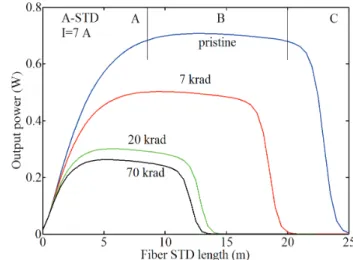
The complex spectroscopic system, leading to the signal amplification by the pumping of the rare-earth ions, results from the competition between different emission and absorption mechanisms at different wavelengths. This explains that the amplifier output power at 1545 nm (or gain efficiency) strongly depends on the length of the active fiber used for its design. This dependence is illustrated in Fig.9 for non-irradiated A-STD amplifier and for the amplifier made with STD fiber samples irradiated at 7 krad, 20 krad and 70 krad. Without ionizing radiations, the output power of an amplifier based on this fiber first increases with the number of pumped active ions (then the RE fiber length) as their contribution to the signal amplification dominates their induced absorption at the signal wavelength (Zone A in Fig.9). For greater lengths, these mechanisms compensate themselves, resulting in a stable output power with length (Zone B). For longer fiber lengths, the pump power is too much low to preserve the population inversion and the signal absorption dominates the RE stimulated emission. As result, the output power abruptly decreases with the fiber length (Zone C).
Fig.9. Comparison between the length dependence of the A-STD 1545 nm output power calculated for the pristine amplifier and the ones made with STD fiber irradiated at 7, 20 and 70 krad (backward pumping scheme).
Simulations also reveal that radiations impact the amplifier efficiency by two possible ways. At low doses, radiations lead to RIA that, for an optimized length before irradiation, decreases the 1545 nm output power, without changing the fact that the used fiber length remains optimal under these new conditions. However, at higher doses, RIA can lead to the whole absorption of the pump at 915 nm before the end of the active fiber. This is dramatic for the amplifier response because inside the active fiber part not pumped, the 1545 nm signal will no more be amplified but will be efficiently absorbed by the Er3+ ions. This finally results in a strong and rapid decrease of the fiber amplifier efficiency with dose.
B. Influence of the Amplifier Scheme
The developed numerical tool is also very efficient to evaluate the radiation tolerance potential of amplifiers designs with two different pumping schemes: backward and forward. In backward scheme, the 1545 nm signal propagates in the inverse direction of the 915 nm pump radiation. This scheme is the one used for the amplifiers tested under radiations as it allows to obtain higher 1545 nm gain for a given pump power at 915 nm. Amplifiers can also be designed in a way where pump and signal propagate along the same direction, called forward pumping scheme. Fig. 10 illustrates the length dependence of the 1545 nm output power for this forward scheme in the cases of pristine or irradiated STD fiber. The length dependence of the A-STD output power differs from the one associated with the backward pumping scheme. In this last scheme, the amplified signal efficiently extracts power from the pump because the 4I13/2 ion population is more inverted at the fiber
end. As result, this pumping scheme is more efficient than the forward one. On the contrary, longer optimal lengths are needed for backward pumping. However, for this case, changing the pumping scheme will be inefficient to improve the radiation hardness of the amplifier based on RH fiber.
0 1 2 3 4 5 6 7 8 0.0 0.2 0.4 0.6 0.8 [Exp; pristine] [Exp; 20krad] [Exp; 40krad]
O
u
tp
u
t
P
o
w
e
r
(W
)
Pump current (A)
Fiber STD
Simulation, non-irradiated Simulation, 7krad Simulation, 20krad
Fig.10. Comparison between the length dependence of the A-STD 1545 nm output power calculated for the pristine amplifier designed with a forward pumping scheme and for the ones made with STD fiber irradiated at 7, 20 and 70 krad.
C. Relative Influences of RIA at the Pump and Emission Wavelengths
From our study, it appears that optimizing the composition of the fiber core and the fiber length efficiently improves the radiation tolerance of fiber-based amplifiers. Simulation tools can also be used to identifying the most influent point defects on the amplifier degradation. In Fig. 11, we compare, for the A-STD amplifier, the impact of doubling the pump losses at 915 nm without changing the 1545 nm losses and doubling the IR losses without affecting the pump propagation with excess losses. By an inspection of this figure, it is clear that losses at 915 nm have a stronger impact on the amplifier degradation. Losses around the signal wavelength decrease the global efficiency of the amplifier without changing the optimization choices made before irradiation. At the opposite, induced losses around the pump wavelength strongly affect the designer choice for the amplifier. As a consequence, future studies must be focused to reduce the RIA around the pump wavelength of amplifiers.
Fig.11. Comparison between the length dependence of the A-STD 1545 nm output power calculated for the pristine amplifier based on STD fiber and by doubling the loss increase at 915 nm or 1545 nm respectively.
V. CONCLUSION
In this paper, we present, an approach coupling experiments and simulations to improve the radiation tolerance of active fibers and fiber-based amplifiers. We validate this approach by comparing our calculations with previous experimental results acquired on Er/Yb-doped amplifiers [14]. Simulation tools, based on Particle Swarm Optimization procedure, permit to reproduce the amplifier behavior before and after irradiation. At this time, only radiation effects on the attenuation properties of the active fibers are implemented in the code but further experiments/simulations will be done to also model the radiation induced changes in the spectroscopic properties of the rare earth ions. With this code and a very limited number of experimental tests, we can predict the impact of varying the amplifier design on its radiation response. The first performed simulations showed that the fiber length of the amplifier should not be optimized before irradiation to attain the maximal gain, as usually done in absence of harsh environment, but must be rather defined to reduce the impact of the radiation-induced losses around the pump wavelength that are shown to be mainly responsible for the gain degradation, and this for the two backward and forward pumping schemes. Future intensive simulations will be performed to investigate the influence of the various parameters on the amplifier performances and to identify the most suitable design for operation in the future space missions. This paper confirms that radiation tolerance of the Er/Yb amplifiers can be efficiently achieved by optimizing their designs, in addition to the improvement of the radiation tolerance of the fiber itself. By combining these two techniques, amplifiers nearly insensitive to space environment may be designed in the future.
REFERENCES
[1] S. Girard, B. Tortech, E. Regnier, M. Van Uffelen; A. Gusarov, Y. Ouerdane, J. Baggio, P. Paillet, V. Ferlet-Cavrois, A. Boukenter, J-P. Meunier, F. Berghmans, J.R. Schwank, M.R. Shaneyfelt, J.A. Felix, E.W. Blackmore, H. Thienpont, “Proton- and gamma-induced effects on erbium- doped optical fibers”, IEEE Transactions on Nuclear Sciences, vol. 54, n°6, pp. 2426-2434, 2007.
[2] G.M. Williams, M.A. Putnam, C.G. Askins, M.E. Gingerich, E.J. Friebele, “Radiation effects in erbium-doped optical fibres”, IEE Electronic Letters 28, pp. 1816-1818, 1992.
[3] H. Henschel, O. Kohn, H.U. Schmidt, J. Kirchof, S. Unger, “Radiation-induced loss of rare earth doped silica fibres”, IEEE Transactions on Nuclear Sciences, vol. 45, n°3, pp. 1552 - 1557, 1998.
[4] M. Ott, “Radiation Effects expected for Fiber Laser/Amplifier and Rare-Earth doped Optical Fibers”, NASA GSFC, Parts, Packaging and Assembly Technologies Office Survey Report, 2004.
[5] G.M. Williams, E.J. Friebele, “Space radiation effects on erbium-doped fiber devices: sources, amplifiers, and passive measurements”, IEEE Transactions on Nuclear Sciences, vol. 45, n°3, pp. 1531 - 1536, 1998.
[6] B.P. Fox, K. Simmons-Potter, W.J. Thomes, D.A.V. Kliner, “Gamma-Radiation-Induced Photodarkening in Unpumped Optical Fibers Doped With Rare-Earth Constituents”, IEEE Transactions on Nuclear Sciences, vol. 57, n°3, pp. 1618 - 1625, 2010.
[7] B.P. Fox; K. Simmons-Potter, D. C. Meister; R. P. Bambha; and D. A. V. Kliner, “Temperature and dose-rate effects in gamma irradiated rare-earth doped fibers” SPIE 7095, 70950B, 2008. [8] S. Girard, Y. Ouerdane, B. Tortech, C. Marcandella, T. Robin, B.
Cadier, J. Baggio, P. Paillet, V. Ferlet-Cavrois, A. Boukenter, J-P. Meunier, J. R. Schwank, M.R. Shaneyfelt, P.E. Dodd, E.W. Blackmore “Radiation Effects on Ytterbium- and Ytterbium/Erbium-doped Double-Clad Optical Fibers” IEEE Transactions on Nuclear Sciences, vol. 56, n°6, pp. 3293 - 3299, 2009.
8
[9] T.S. Rose, D. Gunn, G.C. Valley, “Gamma and proton radiation effect in erbium-doped amplifiers: active and passive measurements”, J. Light. Technol., vol. 19, pp. 1918–1923, 2001. [10] M. Li, J. Ma, L. Y. Tan, Y.P. Zhou , S. Y. Yu, J.J. Yu, and C. Che,
“Investigation of the irradiation effect on Erbium-doped fiber amplifiers composed by different density erbium-doped fibers », Laser Physics, 19(1), pp.138-142, 2009
[11] A. Gusarov, M. Van Uffelen, M. Hotoleanu, H. Thienpont, and F. Berghmans, “Radiation Sensitivity of EDFAs Based on Highly Er-Doped Fibers”, J. Light. Tech. 27(11), 1540-1545, 2009.
[12] M. Alam, J. Abramczyk, P. Madasamy, W. Torruellas, and A. Sanchez, “Fiber amplifier Performance in γ-radiation environment”, OSA/Optical Fiber Conference 2007, paper OMF4.
[13] J. Ma, M. Li, L. Tan, Y. Zhou, S. Yu,Q. Ran, ”Experimental investigation of radiation effect on erbium-ytterbium co-doped fiber amplifier for space optical communication in low-dose radiation environment”, Optic Express, vol.17, n°18, pp. 15571-15579, 2009. [14] S. Girard, M. Vivona, A. Laurent, B.Cadier, C. Marcandella, T.
Robin, E. Pinsard, A. Boukenter, and Y. Ouerdane, "Radiation hardening techniques for Er/Yb doped optical fibers and amplifiers for space application," Opt. Express 20, 8457-8465,2012.
[15] M. Vivona, S. Girard, C. Marcandella, T. Robin, B. Cadier, M. Cannas, A. Boukenter and Y. Ouerdane, “Influence of Ce codoping and H2 pre-loading on Er/Yb-doped fiber: Radiation response characterized by Confocal Micro-Luminescence”, Journal of Non-Crystalline Solids, vol.357, pp.1963-1965, 2011.
[16] Rui-xian Xing, Yu-bang Sheng, Zi-jun Liu, Hai-qing Li, Zuo-wen Jiang, Jing-gang Peng, Lu-yun Yang, Jin-yan Li, and Neng-li Dai, "Investigation on radiation resistance of Er/Ce co-doped silicate glasses under 5 kGy gamma-ray irradiation," Opt. Mater. Express 2, 1329-1335 (2012)
[17] B.-M. Dicks, F. Heine, K. Petermann, and G. Huber, “Characterization of a Radiation-Hard Single-Mode Yb-Doped Fiber Amplifier at 1064 nm”, Laser Physics, Vol. 11, n°1, pp. 134–137, 2001.
[18] J. Thomas, M. Myara, L. Troussellier, E. Burov, A. Pastouret, D. Boivin, G. Mélin, O. Gilard, M. Sotom, and P. Signoret, "Radiation-resistant erbium-doped-nanoparticles optical fiber for space applications," Opt. Express 20, 2435-2444 (2012).
[19] J. Kennedy, R. Eberhart, "Particle Swarm Optimization" in Proceedings of IEEE International Conference on Neural Networks. IV., pp. 1942–1948, 1995.
[20] E.J. Friebele, “Radiation protection of fiber optic materials: effects of cerium doping on the radiation-induced absorption”, Applied Physics Letters, vol.27, pp.210-212, 1975.
[21] E. Yahel, A. Hardy, “Efficiency optimization of high-power, Er3+– Yb3+-codoped fiber amplifiers for wavelength-division-multiplexing applications”, J. Opt. Soc. Am. B, vol. 20, pp. 1189-1197, 2003. [22] E. Desurvire, “Erbium doped fiber amplifiers: principle and
applications”. Wiley interscience, 2002.
[23] M. De Sario, L. Mescia, F. Prudenzano, F. Smektala, F. Deseveday, V. Nazabal,J. Troles, L. Brilland, “Feasibility of Er3+-doped, Ga
5 Ge20Sb10S65 chalcogenide microstructured optical fiber amplifiers,” Opt. & Las. Technol., vol. 41, pp. 99–106, 2009.
[24] A. Bjarlev, “Optical fiber amplifiers: design and system application,” Artech House, 1993.
[25] F. Prudenzano, L. Mescia, A. D’Orazio, M. De Sario, V. Petruzelli, A. Chiasera, and M. Ferrari, “Optimization and characterization of Rare-Earth doped Photonic-Crystal-Fiber Amplifier Using Genetic Algorithm”, J. Lightwave Technol., vol. 25 (8), pp. 2135-2141,2007. [26] G. Fornarelli, L. Mescia, F. Prudenzano, M. De Sario, F. Vacca, “A
neural network model of erbium-doped photonic crystal fibre amplifier”, Optics and Laser Technology, vol. 41, pp. 580-585, 2009. [27] A. Giaquinto, L. Mescia, G. Fornarelli, F. Prudenzano: “Particle swarm optimization-based approach for accurate evaluation of upconversion parameters in Er3+-doped fibers,” Opt. Lett. vol. 36, pp. 142-144, 2011.
[28] J. Kennedy, R. C. Eberhart, Swarm Intelligence, Morgan Kaufmann Publishers, San Francisco, CA, USA, 2001.
[29] A Shooshtari, T. Touam, S. I. Najafi, S . Safavi-Naeini, H . Hatami-Hanza, “Yb3+ sensitized Er3+-doped waveguide amplifiers: a theoretical approach”, Optical and Quantum Electronics, vol. 30, pp.249-264, 1998.
[30] G. A. Sefler, W. Daniel Mack, G. C. Valley, T. S. Rose, “Secondary energy transfer and non participatory Yb3+ ions in Er3+–Yb3+ high-power amplifier fibers”, J. Opt. Soc. Am. B, Vol. 21 pp.1740-1748, 2004.
[31] S. Feng, F. Luan, S. Li, L. Chen, B. Wang, W. Chen, L. Hu, Y. Guyot, G. Boulon, “Determination of energy transfer and
upconversion constants for Yb3+/Er3+ codoped phosphate glass”, Chinese Optics Letters, vol. 8, pp. 190-193, 2010.
[32] D.L. Griscom, E.J. Friebele, K.J. Long, and J.W. Fleming, “Fundamental defect centers in glass: Electron spin resonance and optical absorption studies of irradiated phosphorus-doped silica glass and optical fibers,” Journal of Applied Physics, vol. 54 (7), pp. 3743 – 3762, 1983.
[33] E. Régnier, I. Flammer, S. Girard, F. Gooijer, F. Achten, and G. Kuyt. "Radiation-induced attenuation at IR wavelength in silica based optical fibers", IEEE Trans. Nucl. Sci., vol.54, pp. 1115-1119, 2007.