BJ SHERBROOKE
FACULTE DE GENIEDEPARTEMENT DE GENIE MECANIQUE
GEOMETRIC CHARACTERIZATION AND SIMULATION OF CELL-MEDIATED RESORPTION FOR POROUS BONE SUBSTITUTES USING MICRO COMPUTED
TOMOGRAPHY AND ADVANCED FUZZY METHOD
CARACTERISATION GEOMETRIQUE PAR LA LOGIQUE FLOUE ET SIMULATION DE LA RESORPTION CELLULAIREMENT ASSISTEE DE SUBSTITUTS POREUX POUR TISSUS OSSEUX PAR MICROTOMOGRAPHIE A
RAYONS X
By
Mahdieh Bashoor Zadeh
A Dissertation Submitted in Partial Fulfillment of the requirement for the degree of Doctor of Philosophy
Speciality: GENIE MECANIQUE
Jury committee:
1 - Gamal Baroud (directeur) 4- Said Elkoun 2- Stephan Becker 5- Hassan Serhan 3- Marc Bohner
1*1
Published Heritage Branch 395 Wellington Street OttawaONK1A0N4 Canada Direction du Patrimoine de I'edition 395, rue Wellington OttawaONK1A0N4 CanadaYour We Votre reference ISBN: 978-0-494-75057-5 Our file Notre reference ISBN: 978-0-494-75057-5
NOTICE: AVIS:
The author has granted a
non-exclusive license allowing Library and Archives Canada to reproduce, publish, archive, preserve, conserve, communicate to the public by
telecommunication or on the Internet, loan, distribute and sell theses
worldwide, for commercial or non-commercial purposes, in microform, paper, electronic and/or any other formats.
L'auteur a accorde une licence non exclusive permettant a la Bibliotheque et Archives Canada de reproduire, publier, archiver, sauvegarder, conserver, transmettre au public par telecommunication ou par I'lnternet, preter, distribuer et vendre des theses partout dans le monde, a des fins commerciales ou autres, sur support microforme, papier, electronique et/ou autres formats.
The author retains copyright ownership and moral rights in this thesis. Neither the thesis nor substantial extracts from it may be printed or otherwise reproduced without the author's permission.
L'auteur conserve la propriete du droit d'auteur et des droits moraux qui protege cette these. Ni la these ni des extraits substantiels de celle-ci ne doivent etre imprimes ou autrement reproduits sans son autorisation.
In compliance with the Canadian Privacy Act some supporting forms may have been removed from this thesis.
Conformement a la loi canadienne sur la protection de la vie privee, quelques formulaires secondaires ont ete enleves de cette these.
While these forms may be included in the document page count, their removal does not represent any loss of content from the thesis.
Bien que ces formulaires aient inclus dans la pagination, il n'y aura aucun contenu manquant.
1*1
for their love, support and patience, And
This dissertation consists of the following three manuscripts that have been accepted or prepared for submission as follows: The third chapter presented the first manuscript that it has been published in Acta Biomaterialia 6 (2009), p. 864-875. The fourth and the fifth chapters demonstrated two manuscripts that are prepared for submission in one of the field journals. The first one is entitled "Geometric analysis of porous bone substitutes using
micro-computed tomography and fuzzy distance transform" and the second one is entitled "Effect of subvoxel process on non-destructive characterization of bone substitutes".
Repairing of large bone defects with the use of scaffolds has received significant attention from both the medical and scientific communities because of its potential to accelerate the bone healing process. From the literature, it is known that the scaffold architecture is a key factor in the biological response of the bone to the substitute. The architectural properties include, among others, the pore and interconnection sizes.
Pores provide the space for cells to reside and form new bone tissue while pore interconnections are crucial for cell migration, vascularization and transport of waste products and nutrients. It is therefore important to provide accurate characterization of the porous structure of the scaffold to better understand its biological response. With this understanding, a better design of bone substitute becomes possible.
Generally, an efficient characterization method should be accurate and non-destructive and provides comprehensive information of scaffold architecture. Micro-computed tomography as a non-destructive technique provides access to 3D structure of scaffold, but there are limitations such as how to extract the relevant information from large amount of data. Various methods have been established to quantify the architectural properties from micro-computed tomography data. The main goal of these methods is to enhance the precision of geometric characterization.
The broader objective of this thesis is to provide an improved characterization of the porous scaffolds. A more focused objective is to provide a computational model simulating the cell mediated resorption process of resorbable bone substitutes. Therefore, this study combined both novel image treatments and algorithms to meet these objectives.
The thesis is structured in three scientific manuscripts. The first manuscript used fuzzy-based image treatment methods to analyse images generated by micro-computed tomography. From the literature, it is known that the fuzzy-based method helps to improve the accuracy of the characterization, in particular for scaffolds featuring a relatively small pore size. In addition, a new algorithm was introduced to determine both pore and interconnection sizes. The
investigated scaffolds. Scaffolds made of P-tricalcium phosphate ((3-Ca3(P04)2) and presenting a constant porosity and four variable pore sizes were examined. The average pore size (diameter) of the four bone substitute groups (denominated with a letter from group A to D) was measured to be 170.3±1.7, 217.3±5.2, 415.8±18.8 and 972.3±10.9 urn. Despite this significant change in pore size, the pore interconnection size only increased slightly, in the range of 61.7 to 85.2 urn. The average porosity of the four groups was 52.3±1.5 %. The surface density of scaffolds decreased from 11.5 to 3.3 mm"1, when the pore size increased.
The results revealed that the permeability of scaffolds is in the same order of magnitude and increased from 1.1 TO"10 to 4.1-10"10 m2 with increasing the pore size.
The second manuscript was devoted to the use of subvoxelization algorithm and high-resolution scanner, in an attempt to further improve the accuracy of the results, in particular, of the small pore scaffolds. As expected, an increase of the image resolution from 15 to 7.5 [im significantly eased the segmentation process and hence improved scaffold characterization. Subvoxelization also improved the results specifically in terms of interconnection sizes. Specifically, much smaller interconnection sizes were yielded after applying the subvoxelization process. For example, the mean interconnection size of small pore size groups, group A and B, dropped from 63 to 20 and 30 urn, respectively. Furthermore, due to more details obtained from subvoxelization and high-resolution scanning, additional effects so called "boundary effects" were observed. The boundary effects can yield misleading results in terms of interconnection sizes. The means to reduce these effects were proposed.
The third manuscript focused on the simulation and understanding of cell mediated resorption of bone graft substitutes. A computer model was developed to simulate the resorption process of four bone substitute groups. nCT data and new "image processing" tools such as labelling and skeletonization were combined in an algorithm to perform the steps of resorption simulation algorithm. The proposed algorithm was verified by comparing simulation results with the analytical results of a simple geometry and biological in vivo data of bone substitutes. A correlation coefficient between the simulation results and both
finding is in agreement with the in vivo results. Two definitions were introduced to estimate the resorption rate; volume resorption rate and linear resorption rate. The volume resorption rate was proportional to accessible surface and decreased when the pore size increased, while the linear resorption rate was proportional to thickness of material and increased with increasing the pore size. In addition, the simulation results revealed no effect of resorption direction on resorption behaviour of substitutes. However, the resorption rate of small pore size samples was decreased with increasing the minimum interconnection size required for cell ingrowth, to 100 um.
This thesis combined novel "image processing" tools and subvoxelization method to improve the characterization of porous bone substitutes used in the bone repair process. The improved characterization allowed a more accurate simulation process. The simulation data were consistent with previously obtained biological data of the same group and allows understanding the local resorption process. The available tools and results are expected to help with the design of optimal substitute for bone repair.
Keywords: Bone substitutes, scaffold, ^-computed tomography, image analysis, subvoxelization, image resolution, resorption simulation, resorption rate
L'utilisation de greffons osseux synthetiques pour reparer les defauts osseux prononces est un procede qui a recu de plus en plus Pattention de la part de la communaute scientifique, etant donne qu'il present un potentiel d'acceleration du processus de guerison des os. II est mentionne dans la litterature que I'architecture du greffon osseux synthetique est un facteur cle dans l'acceptation de l'os biologique a son substitut. Ces proprietes architecturelles incluent, entre autres, la taille des pores et des interconnexions.
Les pores constituent un espace dans lequel les cellules peuvent se regenerer pour former de nouveaux tissus osseux, alors que les interconnexions sont cruciales pour la migration des cellules, la vascularisation et le transport des dechets produits et des nutriments. Dans le but de mieux comprendre la reponse biologique de l'os a son substitut, la caracterisation de la microstructure poreuse est done indispensable.
Generalement, une methode de caracterisation ideale se doit d'etre precise, non-destructive et de fournir une information complete sur I'architecture du greffon osseux synthetique. La tomographic assistee par ordinateur est non-destructive et conduit a une caracterisation tridimensionnelle du greffon osseux. Toutefois, cette technique a quelques limitations dont l'extraction de 1'information utile depuis une grande quantite de donnees. Diverses methodes ont ete mises au point afin de quantifier les proprietes architecturales a partir des donnees issues de la tomographic assistee par ordinateur.
L'objectif general de cette these est de fournir une methode amelioree de caracterisation du greffon osseux poreux. Un des objectifs specifiques consiste a proposer un modele de caracterisation de la structure poreuse capable de simuler la resorption des cellules par les substituts osseux. Afin d'atteindre cet objectif, un modele combinant a la fois des traitements d'images et des algorithmes novateurs est propose.
La these est structured autour de trois articles scientifiques. Le premier manuscrit a utilise une methode de traitement d'images dite « fuzzy-based » pour l'analyse d'images generees par tomographie assistee par ordinateur. Dans la litterature, il est dit que la cette methode
utilisant l'algorithme «marching cubes». De plus, la methode dite «Lattice Boltzmann» a ete utilisee pour caracteriser la permeabilite de la structure poreuse de la greffe. Dans cet article, des resultats de caracterisation de differents substituts osseux en phosphate de p-tricalcium (P-Ca3(PC>4)2) d'une meme porosite mais de quatre tailles de pores differentes ont ete presentes. La taille moyenne (diametre) des pores pour chacun des quatre groupes de substituts testes (identifies de A a D) etait de 170,3±1,7, 217,3±5,2, 415,8±18,8 et 972,3±10,9 urn. Malgre cette variation importante de la taille des pores, celle des interconnexions entre les pores n'a que legerement augmente, passant de 61,7 a 85,2 \im. La porosite moyenne des quatre groupes se trouvait a 51,3±1,5%. Lorsque la taille des pores augmente, la densite surfacique est reduite passant de 11,5 a 3,3 mm"1. Les resultats ont
montre que la permeabilite des structures poreuses etaient du meme ordre de grandeur : de 1,1-KT10 a4,l-10"10 m2 avec l'augmentation de taille des pores.
Dans le but d'ameliorer la precision des mesures pour des greffes qui presentent des pores de taille relativement petite, le second manuscrit a ete dedie a l'utilisation d'un algorithme dit de sous-voxelisation et d'un analyseur haute resolution. Tel qu'attendu, 1'amelioration de la resolution de 15 a 7,5 \im a facilite le processus de segmentation des images et a ainsi ameliore la caracterisation des greffons. La sous-voxelisation a notamment ameliore les resultats au niveau de la taille des interconnexions. Plus specifiquement, des tailles d'interconnexions beaucoup plus petites ont ete obtenues suite a l'application de la sous-voxelisation. Par exemple, la taille moyenne des interconnexions mesuree pour les groupes A et B s'est trouvee reduite de 60 a 20 et 30 urn respectivement. De plus, l'augmentation de la resolution obtenue par l'utilisation de l'analyseur haute resolution et de la sous-voxelisation a revele l'existence « d'effets de bord ». Ces effets de bords peuvent mener a des mesures de taille d'interconnexion erronees. Des moyens de reduire ces effets ont ete proposes.
Le troisieme manuscrit est consacre a la simulation et la comprehension du processus de resorption assistee par les cellules pour des substituts de greffe osseuse. Un modele a ete developpe pour simuler le processus de resorption de quatre groupes de substituts osseux. Les donnees (jCT ainsi que des nouveaux outils de traitement d'images tels que
L'algorithme propose a ete verifie en comparant les resultats simules aux resultats analytiques d'une geometrie simple et aux resultats biologiques in vivo de substituts osseux. Un coefficient de correlation superieur a 0,9 a ete obtenu entre les resultats simules, analytiques et experimentaux. Le processus de resorption locale s'est revele plus rapide dans la region externe, particulierement au debut du processus. Cette decouverte est en accord avec les resultats in vivo. Pour estimer la resorption, le taux de resorption volumique et le taux de resorption lineaire ont ete introduits. Le taux de resorption volumique est proportionnel a la surface accessible et inversement proportionnelle a la taille des pores. Quant au taux de resorption lineaire, il est a la fois proportionnel a Pepaisseur du materiau et a la taille des pores. D'un autre cote, la simulation revele que la direction de resorption n'a aucun effet sur le comportement des substituts. Cependant, le taux de resorption pour les echantillons a petits pores a diminue avec Paugmentation de la taille minimale d'interconnexion requise pour la croissance des cellules.
Cette these propose de combiner un nouvel outil de traitement d'images a la methode de sous-voxelisation dans le but d'ameliorer la caracterisation des substituts poreux utilises pour la reparation des defauts osseux. Cette caracterisation precise a donne lieu a des simulations plus realistes qui se revelent coherentes avec des donnees biologiques prealablement prises pour un meme groupe de substitut. Les outils de caracterisation et de simulation mis en oeuvre dans ces travaux apportent, d'une part, une modelisation realiste du phenomene de resorption et, d'autre part, ouvrent des perspectives dans la conception et Poptimisation des substituts pour la reparation osseuse.
Mots cles : Substitut osseux, greffon osseux synthetique, micro tomographie (uCT) par rayons X, Traitement d'images, subvoxelization, resolution d'une image, taux de resorption osseuse, simulation de la resorption osseuse.
These four years of research have been a truly enjoyable experience in my life. I would like to take this opportunity to thank all the people who have made this possible for me. First of all, I would like to express my deepest appreciation to my PhD supervisor, Professor Gamal Baroud, for his guidance and support during these years. It has been a great chance and pleasure to work with him and learn from him. I am heartily grateful to him for his valuable advice, enlightening discussions and positive and encouraging words. I also would like to express my appreciation to him for making it possible for me to attend international conferences inside and outside of Canada.
Furthermore, this research project and direction wouldn't have been possible without the generous support from the Canada Research Chairs Program (CRC), the National Sciences and Engineering Research Council of Canada (NSERC), the Canadian Institute of Health Research (CIHR) and the Robert Mathys Stiftung (RMS).
I would like to sincerely thank Professor Marc Bohner for his critical yet very fruitful advices, discussions and for his attentive curiosity. It has been a great opportunity for me to work with him. I am really grateful to him and his colleagues in 'Robert Mathys foundation' (RMS) in Switzerland for preparing the calcium phosphate porous scaffolds used in this study.
I also wish to express my appreciation to Dr. Steve Allen from 'Centre de calcul scientifique de I'Universite de Sherbrooke' (CCS) for his generous help and the great work he has done in parallelization and modification of my code to accelerate the implementation strategies. I further appreciate a lot Dr. Thomas Zeiser for providing the 'Lattice Boltzmann code' and for his excellent support during the computational analysis. Also I am thankful to Dr. Akbar Darabi for highlighting the use of fuzzy logic in medical imaging and the many useful discussions. I would like to thank Mrs. Irene Kelsey from 'Institut des materiaux et systemes intelligents' (IMSI) center at Universite de Sherbrooke for her patience to teach me how to use u-computed tomography and to scan
Last, but not least, I am grateful to my husband Ali and my daughter Kiana for their great support and patience throughout these years. And finally I thank my parents who taught me valuable lessons about humanity, life and world and for their unconditional support and continuous encouragement during the whole period of my studies.
Summary ii
Acknowledgement viii
Table of contents x
Abbreviation and symbol list xiv
Tables list xviii
Figures list xix
CHAPTER 1 Introduction 1
1.1 Context of the doctorate 1 1.2 Questions of research 4
1.3 Hypothesis 5 1.4 Objectives 6 1.5 Block diagram of the doctorate work 6
CHAPTER 2 Literature survey 8
2.1 Bone defects and repair procedure 8 2.2 Bone substitute and its role in bone healing 92.2.1 Ideal scaffold for bone substitute 9
2.3 Bone substitute material 11
2.3.1 Autografts 11 2.3.2 Allografts 11 2.3.3 Xenografts 12 2.3.4 Synthetic bone graft substitutes 12
2.3.4.1 Metal 13 2.3.4.2 Polymer 13 2.3.4.3 Ceramics 14
2.4 Bone substitute and structural parameters 16 2.4.1 Definition of porous structure 16 2.4.2 Geometrical characteristics of porous structure 16
2.5 Bone substitute paradigms 18 2.5.1 Biological paradigms 18 2.5.2 Structural paradigms 19 2.5.3 Physical and mechanical paradigms 22
2.6 Characterization of structural parameters 24 2.6.1 Traditional methods to measure Porosity and Pore size 25
2.6.2 Recent methods to measure Porosity and Pore size 27
2.6.2.1 Micro Computed tomography (nCT) 27
2.6.2.2 Thresholding 29 2.6.2.3 Distance transform (DT) 31
2.6.2.4 Fuzzy distance transform (FDT) 32
2.6.2.5 Skeletonization 34 2.6.2.6 3-D Geometric analysis of uGT images: The Hildebrand Method 38
2.6.3 Methods to measure specific surface 42 2.7 Fluid flow analysis and lattice Boltzmann method 43
2.7.1 Methods to measure permeability 43 2.7.2 Lattice Boltzmann Method 45
CHAPTER 3 Geometric analysis of porous bone substitutes using
micro-computed tomography and fuzzy distance transform 49
3.1 Abstract 50 3.2 Introduction 50 3.3 Material and Method 54
3.3.1 Scaffold production and preparation 54 3.3.2 Micro-computed tomography 54
3.3.6 Skeletonization and Reconstruction 58 3.3.7 Computing specific surface by marching cube algorithm 59
3.4 Results 59 3.5 Discussion 69 3.6 Reference 76
CHAPTER 4 Effect of subvoxel process on non-destructive characterization
of bone substitutes 81
4.1 Abstract 82 4.2 Introduction 83 4.3 Material and Method 864.3.1 Scaffold fabrication and preparation 86
4.3.2 Image acquisition 86 4.3.3 Subvoxelization process 87
4.3.4 Thresholding 87 4.3.5 Geometric analysis and verification 88
4.4 Results 91 4.5 Discussion 106 4.6 Conclusion 109 4.7 Reference 110
CHAPTER 5 Simulation of cell-mediated resorption of porous bone
substitutes 114
5.1 Abstract 115 5.2 Introduction 115 5.3 Material and Method 117
5.3.1 Scaffold fabrication and Image acquisition 117 5.3.2 Application of the model on the in vivo data 119
5.3.3 Geometric analysis 120 5.3.4 Skeletonization and Reconstruction 121
5.3.7 Prony Method and Resorption Rate 125
5.3.8 Study design 126 5.3.9 Effect of voxel size on resorption simulation 126
5.3.10 Computational platform 127 5.3.11 Provided in vivo data 127
5.4 Results 128 5.5 Discussion 136 5.6 Conclusion 141 5.7 Reference 142
CHAPTER 6 General discussion and conclusion 147
6.1 Image processing and geometric analysis 147
6.2 Fluid flow analysis 149 6.3 Effect of voxel size on geometric parameters 150
6.4 Cell-mediated resorption process 152 6.5 Methodology-synthesis diagram 154
6.6 Contributions 155 6.7 Current limitation 155 6.8 Future work 157 6.9 Discussion et conclusion (Francais) 159
Reference 172
Annexe A Additional scientific contributions 187
A.l Journal publications 187 A.2 Conference/Proceeding publications 187
A AGV Ai c C CFD cs CVF Dfq Umap ^material Dmin D(q) ^scaffold DT DT(p)
f)
FCC FDT FDT(p)f,(x,t)
f(eq) % ) f(t) f(x, I t) HA ICross sectional area of the samples Average gray level value
Rate coefficients of Prony's series Lattice speed
Kozeny constant
Computational fluid dynamic Speed of sound
Ceramic volume fraction
Previously determined fuzzy distance of an adjacent voxel q to p Distance map
Density of scaffold material
Minimum interconnection size required for vascularization Previously determined distance of an adjacent voxel q to p Apparent density of porous scaffold
Distance transform
Distance transform value at p Equilibrium distribution function Face-centered cubic
Fuzzy distance transform
Fuzzy distance transform of voxel p Distribution function of the i-th velocity e,
Equilibrium distribution function of the i-th discrete velocity <?, Intensity of voxel p
Percentage of ceramic volume fraction at time t Single particle distribution function
Hydroxiapatite Input images
L Length of the sample LB Lattice Boltzmann
Lp Fuzzy distance from object voxel, p, to the background MR Magnetic resonance
MVF Material volume fraction N Space dimension
N-b Number-based NeighP Adjacent voxel of P
P, p Pressure Pchse Close porosity Popen Open porosity Ptotai Total porosity
PSvb Volume-base average pore size Q Set of object voxels
q Volumetric flow rate
Qin Accessible ports R Radius of pores
R Correlation coefficient
ROI1 External zone of cylindrical sample ROI2 Middle zone of cylindrical sample ROB Internal zone of cylindrical sample
S Skeleton point, Fuzzy set, Pore surface area SD Standard deviation
SE Skeleton voxels with FDT value less than (Dmin / 2) SEM Scanning electron microscopy
skelet(Q) Skeleton of structure Q SP Set of n points in the plan
sph(x,r) Set of points in a sphere with center x and radius r Ss Nearest skeleton points to Qin
THC Cavity threshold value THM Material threshold value
u Flow velocity
V-b Volume based
Vmtruswn Total intrusion volume Vscajjoid Scaffold volume VOI Volume of interest
wi Weighting factor for different directions
X Set of image voxels
x Space position (coordinate vector of a point in the space)
X(p) Set of center points of all spheres with a radius equal to their corresponding DT value and including the point p
a-TCP a-Tricalcium phosphate (3-TCP p-Tricalcium phosphate
Ap Pressure drop across the specimen
§(pi, pi+1) Integer weight related to membership values and Euclidean distance between pi and pi+1
s Porosity 8 Contact angle
K Permeability X Relaxation time
Xi Eigenvalues of FDT Hessian matrix fi Dynamic viscosity
u(x) Membership value of object's voxel x
\iCT Micro computed tomography
u(p) Membership value of voxel p u Kinematic viscosity
£ Particle velocity
T(P) Local thickness at point p
v, Eigenvectors of FDT Hessian matrix
Q An arbitrary structure in space
QR Distance ridge points co(p) Volume of sphere at voxel p
|\p-q\\ Euclidean distance between/* and q |skelet(Q)| Number of points in the skeleton VDf Gradient of FDT map
Table 2-1 Common biomaterial used for bone repair [Di Silvio, 2007] 16 Table 3-1 Geometrical properties of bone substitutes obtained from introduced image
processing tools 68 Table 3-2 Geometric properties before and after subvoxelization process 71
Table 3-3 Summary of average, standard deviation and variation of permeability values of
samples in each group 72 Table 4-1 Geometrical properties of bone substitutes presented as a function of resolution
and method 96 Table 4-2 Comparing voxel size dependency of structural parameters obtained from scan and
artificial datasets. Arrows (A, T) indicate direction of change in parameters as voxel
size decreased 97 Table 5-1 Geometrical parameters of bone substitutes obtained from fiCT data. The pore size
calculated according to two definitions, number-base and volume-base. The surface density was calculated as the ratio of material surface to total volume, this parameter
was computed by using CT-Analyzer software (CTAN) 130 Table 5-2 Volume and linear resorption rate at different remaining ceramic volume fractions
(CVF), to investigate the pattern of resorption rate over time the resorption rate was calculated at different CVFs (30%, 20% and 10%). The calculation was done on 30 um
resolution images 133 Table 5-3 Volume and linear resorption rate at different remaining ceramic volume fractions
(CVF). To investigate the pattern of resorption rate over time the resorption rate was calculated at different CVFs (30%, 20% and 10%). The calculation was done on 15 (im
resolution images 136 Table 6-1 The porosity calculated based on fuzzified images and reconstructed images.... 149
Figure 1-1 (a) 2-D fuzzy image and (b) 2-D FDT map, local maxima as a representative of pore size are shown with white points and local saddles as a representative of interconnection size are shown with black point. The diameter of corresponding circles
is equal to the pore and interconnection sizes 6 Figure 2-1 2-D image as representative of pores and interconnections 17
Figure 2-2 Schematic representation of Liquid displacement method 26 Figure 2-3 Representative SEM images of scaffolds with different pore sizes, the white bar
corresponds to 0.5 mm [Bohner et al., 2005] 27 Figure 2-4 (a) Sketch of u-Computer Tomography 28 Figure 2-5 The steps to generate 2-D cross section images from radiographic images 29
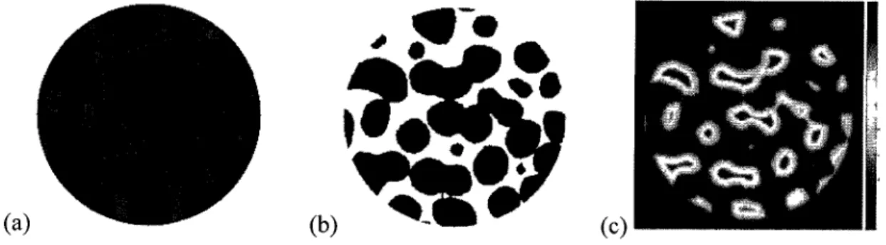
Figure 2-6 2-D representative of (a) original |^CT image, (b) binary image and (c) DT map.32
Figure 2-7 Thinning skeleton, the darkest pixels represent the skeleton of object 35 Figure 2-8 Voronoi skeleton, (a) Some border points of a rectangle form the set of generating
points, (b)The Voronoi diagrams are displayed as dashed lines and the skeleton (black
lines) is estimated based on the Voronoi diagrams 36 Figure 2-9 2-D representative of distance transform skeleton (dotted line), as the locus of
maximal disks (2-D) or spheres (3-D) which are set into the object 36 Figure 2-10 (a) The original binary image and (b) The DT map of binary image, the bright
points are local maxima in DT map and considered as skeleton of object 37 Figure 2-11 Local thickness x (p) of a structure Q determines by fitting maximal spheres to
the structure [Hildebrand and Ruegsegger, 1997] 39 Figure 2-12 Typically uCT reconstructed structure [Bohner et al., 2005] 41
Figure 2-13 (a) 2D FDT map, local maxima as a representative of pore size are shown with dark points.(b) Corresponding circles at local maxima with radius equal to their FDT. 41
Figure 2-14 15 unique cube configurations 43 Figure 2-15 Discrete velocity set for the D3Q19 model 46
samples 60 Figure 3-3 2-D fuzzified images selected from first specimen of each group, the threshold
values, The and TIIM, are (a) sample A, Thc=35 and T1IM=50, (b) sample B, Thc=30 and
ThM=55, (c) sample C, Thc=30 and ThM=55 and (d) sample D, Thc=30 and ThM=50.. 61
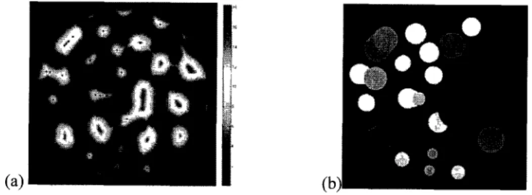
Figure 3-4 FDT maps of (a) Sample A, (b) Sample B, (c) Sample C and (d) Sample D. The
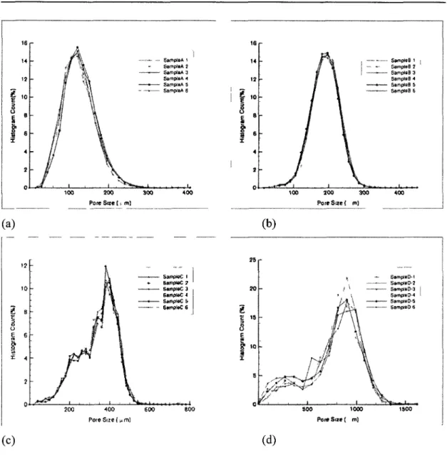
FDT values are in voxel unit 62 Figure 3-5 Number-based pore size distribution of bone substitute structures (before applying
exclusion conditions) derived from max-min operation and FDT values, (a) Group A;
(b) Group B; (c) Group C; (d) Group D 64 Figure 3-6 Number-based pore size distribution of bone substitute structures after applying
exclusion criteria, (a) Group A; (b) Group B; (c) Group C; (d) Group D 65 Figure 3-7 Volume-based pore size distribution of bone substitute structures, (a) Group A;
(b) Group B; (c) Group C; (d) Group D 66 Figure 3-8 Interconnection size distribution of bone substitute structures derived from
max-min operation and FDT values, (a) Group A; (b) Group B; (c) Group C; (d) Group D. 67 Figure 3-9 Velocity map of bone substitute (sample D-l) with stream lines show the flow
direction through the bone substitute structure 73 Figure 3-10 (a) Bone substitute average pore and interconnection size versus four different
bone substitute groups, (b) Bone substitute permeability and surface density versus four
different bone substitute groups 75 Figure 4-1 (a) Fuzzified image of an individual void space, (b) 2-D fuzzy distance transform
map; The pore size and interconnection size is defined as the diameter of circles in 2-D (or spheres in 3-D) centered at local maxima (white points) and saddle voxels (black
points), respectively 90 Figure 4-2 (a) Representative illustration of 2-D fuzzified image (left) and fuzzy distance
transform (FDT) map (right) of individual void space extracted from images of 30 urn resolution. The local maximums are shown as white points in FDT map. (b) Corresponding illustration of 2-D fuzzified image (left) and FDT map (right) after applying subvoxel process. The surface irregularities are appeared by decreasing the
Figure 4-3 2-D representative |u,CT slices of samples A, B, C and D scanned at 30, 15 and 7.5
um resolutions 93 Figure 4-4 Intensity histograms of uCT images of samples A, B, C and D at various
resolutions (Continue on next page) 94 Figure 4-5 Number-based pore size distributions of (a) Sample A, (b) Sample B, (c) Sample
C and (d) Sample D derived from max-min operation and FDT values at different scan
and artificial resolutions 99 Figure 4-6 Interconnection size distributions of (a) Sample A, (b) Sample B, (c) Sample C
and (d) Sample D derived from max-min operation and FDT values at different scan and
artificial resolutions 100 Figure 4-7 Average interconnection size versus intersected volume (a) Sample A, (b) Sample
B, (c) Sample C and (d) Sample D. in each point, the virtual interconnection with intersected volume larger than X% (60-90%) were removed and average interconnection
size was calculated 102 Figure 4-8 The impact of numerical effect on interconnection size distribution of (a) Sample
D-15 |iim scan, (b) Sample D-15 (am artificial and (c) Sample D-30 \im scan. Removing the virtual interconnections considerably affect on distribution of interconnections larger
than 300 um (Continue on next page). OV is overlapping volume 103 Figure 4-9 Percent errors relative to high resolution datasets versus four different bone
substitute samples. Voxel size/pore size ratio calculated based on voxel size of 30 \im and corresponding computed pore size. El (30-15): represent the percent error between the pore size analysis at 30 p,m and 15 urn E2 (15-7.5): represent the percent error between the pore size analysis at 15 um and 7.5 um. E3 (30-7.5): represent the percent
error between the pore size analysis at 30 um and 7.5 urn 105 Figure 5-1 Representative SEM photos of the macropore structure of four groups of p-TCP
scaffolds with different macropore sizes, (a) group A, (b) group B, (c) group C and (d)
group D. The scale bar corresponds to 50 urn [23] 119 Figure 5-3 (a) Porous blocks with isolated spherical pores that are ordered in FCC lattice, (b)
Schematic representation of blocks resorption. Resorption occurred from both sides of the blocks with perpendicular direction to block surface (arrows direction). The large circles, which were drawn by break lines, represent the pores that have been enlarged by resorption, r is the pore radius, d is the inter-pore distance and Dmin is defined as the
minimum interconnection size required for vascularization and migration of the cells
into the porous structure 122 Figure 5-4 2-D representative of resorption steps, (a) Pores are labeled, (b) The skeleton
point are extracted, SE are skeletons with FDT value less than Dmin/2, (c) Pores and
interconnections with diameter less than Dmin are blocked by growing the circles (or
spheres in 3D) centered at SE with the radius equal to FDT value of that point, (d) Skeleton branches corresponding to open pores with appropriate FDT value (i.e. larger than Dmin/2), are detected (f) Pores that can be accessed from the outside are defined, (g)
One voxel layer is "resorbed" or "removed" from the accessible surface. (The red lines " ", in figures (b), (d) and (f), are the skeleton voxels of non-resorbed pores) 124 Figure 5-5 The left axis presents the simulation data (0) and the exponential series
approximation (Prony-series) of the simulation results (•). The right axis presents the resorption rate data (A) which was obtained from the first derivative of Prony-series
with respect to time 125 Figure 5-6 Schematic representation of three zones in cylindrical scaffold, ROIl: outer zone,
ROI2: middle zone and ROB: inner zone 127 Figure 5-7 (A)Analytical and (•) simulation results of FCC lattice of pores with various pore
radius ranging from 100 to 500 um. The porous blocks had a width of 5mm and
inter-pore distance of 22 um. A voxel size of 10 um was set to create the blocks 129 Figure 5-8 Resorption simulation of the four groups of scaffolds have been presented based
on different setting conditions, (a) group A, (b) group B, (c) group C and (d) group D. Depending on the minimum interconnection size required for blood vessel ingrowth and the resorption direction, the resorption process of each group was analyzed four times.
Figure 5-9 Simulation data of four scaffold groups were compared to experimental data. The experimental data were obtained from uGT analysis of samples implanted in bone defects of sheep for 6, 12 and 24 weeks, (a) group A, (b) group B, (c) group C and (d)
group D 132 Figure 5-10 Volume resorption rate (CVF1) at three different zones (ROI1, ROI2 and ROB),
of scaffold groups, (a) group A, (b) group B, (c) group C and (d) group D. The CVF'_ROI represents the volume resorption rate as a function of time for various
location of scaffold 134 Figure 5-11 Resorption simulations of substitutes were processed based on two different
voxel sizes (15 \im and 30 |am), (a) Sample A, (b) Sample C, (c) Sample D. The resorption simulation of small pore size samples, A and B, were affected by voxel size at earlier resorption time. The resorption simulation of samples C and D were not
influenced by voxel size 135 Figure 6-1 (a) 2D FDT map, local maxima as a representative of pore size are shown with
dark points, (b) 2D FDT map, local saddles as a representative of interconnection size
are shown with dark points 148 Figure 6-2 Gray level histograms of sample A (the small pore size sample) at (a) 30 |im
resolution and (b) 7.5 um resolution 150 Figure 6-3 Sensitivity of samples' porosity to threshold values, AGV is the average gray
level value. The threshold domains were selected as ±5%, ±10%, ±15% and ±20 % of
AGV 151 Figure 6-4 Methodology-Synthesis diagram, combination of methods and algorithm used for
CHAPTER 1
Introduction
1.1 Context of the doctorate
Bone as a living tissue is able to restore its functionality and health. However, in large bone defects, where a critical size of bone is missing or damaged, the bone repair mechanism fails to repair the defects. Large bone defects caused by pathological conditions (e.g. cancer) or rapid degradation because of age and disease (i.e. osteoporosis) or massive trauma as well as diseases of bone quality itself, such as osteoporosis, are still a major problem in orthopedics [Mastrogiacomo et al., 2005; -Celil et al., 2007]. In these cases, patient comfort and bone functionality can be surgically restored by reconstructive surgery and bone augmentation. Bone grafting has been considered as a successful therapy for treatment of large bone defects [van Gaalen et al., 2008]. Bone grafting is a surgical procedure to replace missing bone with bone graft or substitutes [Hing, 2005 a]. Due to complications of traditional allografts and autografts, such as pain, morbidity, disease transform and limited availability, there was a great demand for developing synthetic bone substitutes to overcome these complications [Hing, 2004a; Hing, 2005a; Goldberg, 1992; Parikh, 2002].
The bone substitute should not only replace the missing bone, but it should favour the new bone formation and provide an adequate framework for bone ingrowth and vascularization into the substitute [Hing, 2005a; van Gaalen et al., 2008]. Therefore, the geometric parameter and the materials used for fabrication of porous bone substitute should provide the biological and biomechanical properties to enhance the functionality of bone substitute.
Metallic porous bone substitutes show excellent mechanical properties. However, their application is limited due to their lack of degradation and limited tissue adhesion
[Karageorgiou and Kaplan, 2005]. In the other hand, the polymeric biomaterials are biocompatible and biodegradable. Natural polymers are highly biodegradable and used in composite biomaterials to improve their degradation rate. The synthetic polymers can be fabricated with controllable degradation rate. Nevertheless, the poor mechanical properties of polymeric biomaterials limit their application [Karageorgiou and Kaplan, 2005; Yang et al., 2001]. Ceramic biomaterials, such as calcium phosphate ceramics, show biocompatible and bioactive properties. Bioceramics are mechanically resistant under compression but week and largely brittle under tension and shear loads [Moore et al., 2001; Khang et al., 2007]. Hydroxyapatite ceramics exhibits low resorption rate whereas other composition of calcium phosphate ceramics such as p-tricalcium phosphate ceramics are resorbed readily [Ruhe et al., 2007, Wagoner Johnson and Herschler, 2010]. It should be noticed that the rate of degradation can be affected by several factors such as crystallinity and crystal perfection [Karageorgiou and Kaplan, 2005; Yang et al., 2001]. Calcium phosphate ceramics have been considered as promising material for bone substitute due to their excellent biocompatible, bioactive, bioresorbable, osteoconductive and osteointegrative properties [Grynpas et al., 2002; Yuan et al., 1998; Ohura et al., 1996; Dong et al, 2002; Daculsi et al.,2003]. However, they are still in development to enhance their functionality.
Besides the material property, the structure of bone substitute plays an important role in cell attachment, penetration depth and vascularization. There is a common agreement that bone substitutes should have an interconnected porous matrix (so-called 'scaffold') to allow new bone ingrowth and vessel formation [Lu et al., 1999; Mastrogiacomo et al., 2006; Gauthier et al., 1998]. The scaffold properties and characteristics, such as porosity, pore size, interconnection size and surface area, have been considered to be critical factors in functionality of bone substitute [Ho and Hutmacher, 2006; Ma et al., 2006]. In such porous material, pores provide a space for cells to reside and form new bone tissue while the interconnections provide the ways for cell migration, vascularization and transport of waste products and nutrients [Lu et al., 1999; Mastrogiacomo et al., 2006]. It is therefore important to characterize the structure of scaffolds to better understand the biological response. With this knowledge, a better design of scaffold becomes possible. For this purpose, an effective scaffold assessment is required at initial steps of research
and development to select and design scaffolds with appropriate properties [Ho and Hutmacher, 2006]. Various characterization techniques have been developed to evaluate geometric parameters of scaffold. An effective characterization method should be fast, accurate and non-destructive, while providing comprehensive information of all morphological and architectural properties [Ho and Hutmacher, 2006].
Micro-computed tomography (uCT) has been introduced to provide access to 3-D structure of scaffold and allow for precise quantification of geometric parameters. Moreover, the use of |uCT is non-invasive and non-destructive [Ho and Hutmacher, 2006; van Lenthe et al., 2007]. \iCT also provided an accurate measurement of bone ingrowth inside the scaffold and evaluation of resorption kinetics [van Lenthe et al., 2007; Jones et al., 2009]. Various methods and algorithms have been developed to quantify the geometric parameters from |iCT images.
The first focus of this thesis is to improve the characterization of geometric parameters of calcium phosphate bone substitutes. This study combines novel image treatment techniques and algorithms to support more precise characterization of the porous scaffolds. For this purpose, the fuzzy-based methods are applied on |iCT images to improve the accuracy of the characterization [Saha et al. 2002; Saha and Wehrli, 2004]. Fuzzy-based methods consider the fuzzy nature of |^CT images and preserve more information from original \iCT images and therefore allow accurate characterization, in particular, when the resolution of images is relatively low [Sladoje et al., 2005; Saha and Wehrli, 2004]. In addition, a new algorithm has been developed to determine both pore and interconnection sizes and their corresponding distributions. In an attempt, to further improve in the accuracy of geometric parameters, this study also mentions to decrease the voxel size of [iCT images using subvoxelization algorithm and high resolution scans. Decreasing the voxel size provides more structural information and leads to precise characterization. Moreover, a well-established Lattice Boltzmann method is used to simulate the fluid flow in complex porous structure and measure the permeability of scaffolds.
Furthermore, the calcium phosphate bone substitutes are resorbable. The resorption rate of the calcium phosphate scaffolds should be controlled to match bone ingrowth in vivo and repair process. The resorption rate can be controlled by structural design. A few years ago, an analytical model was proposed by Bohner and Baumgart [Bohner and Bumgart, 2004] to predict the effect of geometric parameters on cell mediated resorption of ceramic bone substitutes. This thesis also aims to study the resorption behavior of resorbable bone substitutes and fulfill the analytical model presented in previous study [Bohner and Bumgart, 2004] by simulating the in vivo behavior of porous bone substitute. Therefore, a numerical algorithm is presented to simulate the resorption process of calcium phosphate bone substitutes. The simulation algorithm uses uCT images and fuzzy image processing tools to enhance the precision of simulation.
1.2 Questions of research
Q. Scientific
How to improve the characterization of the pore and interconnection sizes of the micro-porous bone substitute?
Is subvoxelization a valid method to improve characterization?
What is the effect of geometric parameters on permeability and fluid flow analysis of bone substitute?
What is the effect of geometric parameters on resorption behavior of bone substitute? Does interconnection size have any influence on resorption rate of bone substitutes? Does the resorption direction effect on resorption rate?
Q. practical
How can we enhance the characterization precision of geometric parameters?
What is the relation between the voxel size and segmentation/thresholding of uCT images?
What is the optimum resolution for analysis of structural parameters? What is the effect of voxel size on characterization of structural parameters?
Does voxel size have any effect on numerical methods used for quantification of structural parameters?
What is the effect of resolution on resorption analysis of bone substitutes? Q. biomechanics
How can we explain the biological behavior of porous bone substitute based on its geometric properties?
How can we predict the biological behavior of bone substitute based on its geometric and fluid flow properties, in order to design an efficient scaffold for bone substitute?
1.3 Hypothesis
The main hypothesis in this study is related to the definition of pore size and interconnection size. Due to the shape of pores in the structure of calcium phosphate bone substitutes, it was hypothesized that the fuzzy distance transform (FDT) value of local maxima in FDT map is an appropriate value to represent the pore size. It would be corresponding to the diameter of the largest spheres that was located inside the pores (Figure 1-1). Also, because of the shape of interconnections in the structure of calcium phosphate bone substitutes, it was hypothesized that the FDT value of local saddles in FDT map could be suitable value to define the interconnection size. It would be corresponding to the diameter of the spheres that blocked the fenestration between two or more pores (Figure 1-1).
A second hypothesis relates to the resorption process in that I assume that the pore and interconnection sizes are the key determinants of the cell mediated resorption process. Specifically, an algorithm and a simulation model are to be developed to help understand the resorption process as a function of the pore and interconnection sizes. Therefore, the
skeleton of the structure is used to define the accessible pores and interconnections for resorbing cells.
Figure 1-1 (a) 2-D fuzzy image and (b) 2-D FDT map, local maxima as a representative of pore size are shown with white points and local saddles as a representative of interconnection size are shown with black point. The diameter of corresponding circles is equal to the pore and interconnection sizes.
1.4 Objectives
The main objective of this thesis is first to improve the characterization of porous bone substitutes and second to provide a computational model to simulate the cell mediated resorption process of resorbable bone substitutes. Toward the ultimate target, this study combines both novel image treatment and algorithm to reach the objective of the thesis.
Specifically, this study aims to apply the fuzzy image processing technique and developed algorithm to enhance the accuracy of the pore and interconnection size characterization. In addition, subvoxelization algorithm and high resolution j^CT scans will be used to further investigate the accuracy of geometric analysis.
Moreover, this study aims to establish a computer model to simulate the resorption process of resorbable bone substitutes. The effort will be paid to better understand the cell mediated resorption process of calcium phosphate bone substitute. Calculation of resorption rate and investigation of resorption at various locations will be also the targets of this study.
Subvoxelization
Artificially decreasing the voxel
Resorption simulation
Characterized parameter: L Resorption rate
Image acquisition
Gray level histogram and thresholding
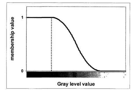
Fuzzification
Define the membership value of each object's voxel
3-D fuzzy distance transform
calculate the shortest fuzzy distance from each voxel of void space to
background
Skeletonization
Extract the ridge point from FDT map
Reconstruction
Create binary images based on their fuzzy nature
CTAN-Analyzer
Apply marching cube algorithm
J Characterized parameter: I Specific surface
Characterized parameter: porosity
Geometric characterization using MaxMin algorithm
Fluid flow analysis using Lattice Boltzmann method
Characterized parameter: Pore size, Interconnection size Characterized parameter: Pressure drop, Velocity map Darcy law Characterized parameter: Permeability
CHAPTER 2
Literature survey
2.1 Bone defects and repair procedure
The bone defects can be caused by "missing" or "defective" bone tissue [Celil et al., 2007]. Celil and his colleagues classified the bone defects into two types. First type is the deformities in which tissue elements are not missing, and the defect is caused by abnormal anatomy, like fracture malunion. This case can be repaired by rearranging or augmenting the defected tissue. Second type of defects is occurred by the damage or missing of bone tissue, like cancer. In this case the repair is possible by tissue replacement [Celil et al., 2007].
Generally, as a living tissue, bone is able to restore its functionality and health. For small size fracture (like a crack), after initial stabilization, the healing process begins based on bone repair mechanism [Hing, 2004a]. Simple bone break fractures are usually treated by external or internal fixation of the fracture site using splints and casts or plates and pins, respectively [Hing, 2004a]. These methods provide the local stability required for bone regeneration. However, according to the material used for internal fixation, second surgery is often required to remove the metallic device used for fixation. Spinal fragility fractures, as a result of aging and diseases, such as osteoporotic vertebral fractures, are repaired by injecting acrylic or calcium phosphate cements into weakened vertebrae to augment them [Baroud et al. 2004; Baroud et al. 2005; Baroud et al. 2006]. In large bone defects, where a critical size of bone is missing or damaged [Hing, 2004a], bone repair mechanism fails to restore the defects as a result of fracture size or infection [van Gaalen et al., 2008]. Reconstructive orthopedic surgery highly demands for bone replacement to repair the large bone defects and treat relative diseases such as spinal fusion, bone cancer, accidental trauma cases and hip fracture. Bone grafting has been introduced as a successful therapy for treatment of such large bone defects [van Gaalen et al., 2008].
2.2 Bone substitute and its role in bone healing
Bone reconstructive surgery is the procedure of replacing missing bone with bone grafts or bone substitutes. The bone substitutes should not only fill the bone defects, but also must stimulate the body to repair itself and facilitate the healing procedure [van Gaalen et al., 2008]. Typically, a bone substitute consists of the scaffold (matrix), viable cells and bioactive agents [Hutmacher et al., 2008; Langer and Vicente, 1993]. A scaffold acts as a temporary 3-D support for cells to adhere, proliferate, differentiate and form new bone to restore the functionality of tissue, while the bioactive cells manage the healing process [Yarlagadda et al., 2005; Wozniak and El Haj, 2007]. Thus, a scaffold should provide the biochemical, biomechanical and structural properties to accelerate healing process.
2.2.1 Ideal scaffold for bone substitute
A scaffold is meant to be invaded by cells and should provide chemical and physical properties to ensure adequate bone ingrowth. An ideal scaffold should fulfill specific requirements. Ideally, the biomaterial used for bone substitute application should provide the following biological characteristics [Moore et al., 2001; Celil et al., 2007]:
(i) Biocompatibility, the ability to match with living cells and tissues without eliciting any undesirable effects in those cells;
(ii) Osteogenesis, 'the formation of new bone by osteoblastic cells present within the graft material' [Moore et al., 2001];
(iii) Osteoinduction, 'the ability to induce differentiation of pluripotential stem cells from surrounding tissue to an osteoblastic phenotype'[Moore et al., 2001];
(iv) osteoconduction, 'the ability to support the growth of bone over its surface' [Moore et al., 2001];
(v) Osteointegration, 'the ability to chemically bond to the surface of bone without an intervening layer of fibrous tissue' [Moore et al., 2001].
Furthermore, many studies have demonstrated that the geometry and architecture of scaffolds also affect their biological response and their ability to remodel to their environment. Therefore, an ideal scaffold should also possess the following properties [Hutmacher, 2000; Agrawal and Ray, 2001].
(vi) The scaffold structure should be 'three dimensional and highly porous with interconnected pore network' to allow cells ingrowth and transport of nutrients and waste products;
(vii) The pores in the porous structure should have adequate size for cells;
(viii) The scaffold should have a surface conductive for cell attachment, proliferation, and differentiation;
(ix) The scaffold should be bioresorbable with controllable resorption rate to mach the bone repair or regeneration process. The resorption rate can be controlled by biomaterial or structural design.
In addition an ideal scaffold should provide specific mechanical and physical properties.
(x) It should possess adequate mechanical properties like those of the tissue at implantation site;
(xi) It should have high permeability to allow cell penetration.
At macroscopic level (mm-cm), the shape and composition of scaffold will affect its toxicity, cell penetration and differentiation into the structure. At intermediate level (100
\xm), the geometric parameters in terms of pore and interconnection sizes, orientation and
surface chemistry will determine the ability of cells to penetrate inside the structure and affect the transport of nutrient and waste products. At microscale level (10 urn), the local surface texture and porosity will affect the protein adsorption and cell adhesion [Griffith, 2002]. Therefore, a comprehensive assessment of scaffold characteristics at each level is critical for understanding its biological behavior.
In the following sections, the current materials used for bone substitute will be reviewed. It will be followed by important geometrical parameters of porous structure and the bone substitute paradigms available in literature.
2.3 Bone substitute material
The bone grafts which are directly derived from real bone are classified into three types; autograft, allograft and xenograft [Baksh, 1999; Wozniak and El Haj, 2007; Laurencin et al., 1999]. In contrary to these types of grafts, the synthetic bone substitutes are produced from biocompatible materials. The properties of each type of grafts and biomaterials used for bone reconstruction are discussed subsequently.
2.3.1 Autografts
Autografts are obtained from the patient's body and transplanted to the damage organ. This type of grafts is still considered as the "gold standard" in bone replacement due to their excellent osteogenic, osteoinductive and osteoconductive properties [Wozniak and El Haj, 2007; Finkemeier, 2002; Hing, 2004a; van Gaalen et al., 2008]. However, their application is limited because of the following reasons: (a) The amount of harvested bone required for defect site is limited [Hing, 2004a; Baksh, 1999; Wozniak and El Haj, 2007; Wozniak and El Haj, 2007], (b) The autograft harvesting lengthens the surgery procedure, [van Gaalen et al., 2008 ], (c) Post operative complications due to donor-site morbidity, pain, infection and structural weakness [Polly and Kuklo, 2002] and (d) Inability to form the harvested bone shape for optimal function [Goldberg, 1992; Goldberg, 1993; Parikh, 2002].
2.3.2 Allografts
Allografts are harvested from human donor and stored in tissue banks [Wozniak and El Haj, 2007]. Although, using allografts overcomes the autografts limitation, there is still some restriction related to their application. Despite using very strict preparation procedure, there is the possibility of infection, transmission of disease and immunogenicity of the grafts [van Gaalen et al., 2008; Laurencinet al., 1999]. Also in this
case, the blood vessels form very slowly and less extensive than in autografts [van Gaalen et al., 2008; Barriga A, 2004].
2.3.3 Xenografts
Xenografts as another alternative to autografts, are harvested from a species other than human (e.g. Bovine clef bone) [Baksh, 1999; van Gaalen et al., 2008]. These materials are mainly used as mechanical filler to inhibit ingrowth of soft tissue [Baksh, 1999]. The tissue rejection due to immunological problem is the application risk associated with their use [Charalambides et al., 2005; Charles-Harris, 2007].
2.3.4 Synthetic bone graft substitutes
Due to the limitation and complication of the abovementioned grafts, there is an increasing demand for development of synthetic bone graft substitute that would be free from the problems associated to donor site morbidity, disease transfer and inadequate supply of material [Hing, 2004a; Hing, 2005a]. Synthetic bone graft substitutes, fabricated from metals, polymers, ceramics and composites, have been introduced as an alternative to the previous types of grafts. The first generation of synthetic materials for use in the human body was introduced in 1960s and 1970s [Hench and Polak, 2002]. The earlier biomaterials were mainly designed to 'achieve a suitable combination of physical properties to match those of the replaced tissue with a minimal toxic response in the host tissue' [Hench, 1980]. These materials were 'nearly inert' and were separated from the host tissue by growing a thin, fibrous capsule [Hench, 1980]. Finally, due to non-integration between the implant and surrounding tissue, the implants often loosen [Hench, 1980]. In 1980s, the second generation biomaterials were developed to be either bioactive or bioresorbable [Hench and Polak, 2002]. The significant advantage of bioactive materials is forming strong bonds to host tissue [Hench, 1998]. Another advantage of second generation was developing resorbable materials that are replaced by regenerated tissue [Hench and Polak, 2002]. Development of bioactive and bioresorbable material has been a great improvement in orthopedic application. However, the implants' life time analysis revealed that a third to half of implants fail within 10-25 years and revision surgery will be required [Hench and Polak, 2002]. The third generation biomaterials were
designed to motivate specific cellular responses. They were developed to interact with cells and activate certain genes to, specifically, stimulate regeneration of living tissue [Hench and Polak, 2002]. For this type of biomaterials, the bioactive and resorbable properties have been combined to help the body repair itself in a good and rapid way. Potential materials used as bone substitutes can be divided into: metals, polymers, ceramics and composite materials.
2.3.4.1 Metal
Typical metallic implants used for bone reconstruction are stainless steel, titanium alloys and cobalt alloys. An excellent mechanical property is the main advantage of metallic implants. Due to their mechanical stability, they have been widely used as implant material for bone repair (e.g. hip replacement device). However, the lack of degradation and non-integration to surrounding tissue limit their application and second surgery will be required to remove the implant, or in the case of permanent implantation there is the risk of toxicity/ allergic reaction [Karageorgiou and Kaplan, 2005; Yang et al., 2001].
2.3.4.2 Polymer
Polymers are known as the largest group of biomaterials [Charles-Harris, 2007]. Both natural and synthetic polymers are used in orthopedic applications. The natural polymers, such as collagens, glycosaminoglycan, chitosan, etc. [Yang et al., 2001; Meyer and Wiesmann, 2006] offer the advantage of biocompatibility, biodegrability and easy processing [Karageorgiou and Kaplan, 2005; Khang et al., 2007]. However, their application is limited due to their high rate of degradation [Karageorgiou and Kaplan, 2005], poor mechanical properties [Karageorgiou and Kaplan, 2005; Yang et al., 2001] and low reproducibility [Charles-Harris, 2007].
The synthetic polymers, such as polylactic acid and poly (lactic-co-glycolic acid), have been developed to overcome the limitation of natural polymers. They provide a large range of bone substitutes with controlled degradation rate and different geometrical and mechanical properties [Karageorgiou and Kaplan, 2005]. They also have the advantage of high reproducibility and can be fabricated in large-scale [Charles-Harris, 2007]. Synthetic
polymers based on biodegradable polyhydroxyacids, such as poly-lactic-glycolide, have been widely used for bone replacement due to their excellent cell adhesion and cell proliferation [Meyer and Wiesmann, 2006]. The limitations associated with use of synthetic materials are their low mechanical properties (even in solid form) [Karageorgiou and Kaplan, 2005] and their acidic degradation products that may reduce biocompatibility [Yang et al., 2001].
2.3.4.3 Ceramics
Ceramics have been specifically used as artificial matrix for bone repair applications [Yang et al., 2001; Charles-Harris, 2007]. The ceramic biomaterials can be classified into three groups based on their chemical activity [Charles-Harris, 2007; Yang et al., 2001; Khangetal., 2007].
(a) Bioinert ceramics, such as alumina and zirconia, have the great advantage of biocompatibility and high mechanical properties such as excellent compressive strength and high resistance to wear [Thamaraiselvi and Rajeswari S, 2004]. However, they do not show ionic interaction with the surrounding tissue, in other word they have weak osteointegration properties. A relationship between the implant and host bone is formed due to mechanical bonds which are created by the stresses on the implant [Moore et al., 2001].
(b) The second type of bioceramics is the surface bioactive group. This group includes bioglasses, glass-ceramics and synthetic hydroxyapatite ceramics [Charles-Harris, 2007; Yang et al., 2001]. The bioglasses and glass-ceramics show excellent mechanical properties, bioactivity, biocompatibility and no toxicity [Thamaraiselvi and Rajeswari S, 2004]. The hydroxyapatite ceramics have a composition similar to the mineral component of bone. They exhibited excellent biointegration properties and have been used to coat metal implants to improve their osteointegration [Moore et al., 2001]. Hydroxyapatite ceramics are mechanically resistant under compression, but they are week and brittle under tension and shear loads [Moore et al., 2001; Khang et al., 2007].
(c) The third group of ceramics is bioresorbable ceramics such as, coralline, tricalcium phosphate (TCP), soluble biocompatible glasses, a and P tricalcium phosphate (a-TCP, p-TCP), etc [Khang et al., 2007; Charles-Harris, 2007; Yang et al., 2001]. Calcium phosphate family has the advantages of biocompatibility, osteointegrativity, osteoconductivity and no toxicity [Moore et al., 2001]. The calcium phosphate ceramics are brittle under tensile and shear and strong under compression loads [Moore et al., 2001]. P-TCP ceramics in porous form have compressive strength and tensile strength similar to cancellous bone [Moore et al., 2001; Jarcho, 1981; Miranda et al., 2008]. Although, these ceramics are mechanically brittle and fragile, they should preserve their structure and mechanical stability of their structure during the initial period of implantation [Charles-Harris, 2007; Hing, 2005]. Therefore, the degradation rate must be controlled to mach new bone formation [Charles-Harris, 2007].
2.3.4.4 Composites
Composite materials are introduced as the combination of two or more individual materials that are able to act synergistically to enhance the properties provided by each material alone [Thamaraiselvi and Rajeswari S, 2004]. Composites made from bioinert and bioactive ceramics are fabricated to attain bioactive material with mechanical strength. Coating porous titanium scaffolds with calcium phosphate led to earlier and greater bone ingrowth and improved mechanical properties [Tache et al., 2004]. Biphasic calcium phosphate ceramics composed of tricalcium phosphate and hydroxyapatite ceramics were developed to achieve resorbable ceramics with controllable resorption rate. Table 2-1 summarizes the common polymers, ceramics and composites used for bone repair application [Di Silvio, 2007].
Table 2-1 Common biomaterial used for bone repair [Di Silvio, 2007] Polymer • Polylactic acid • Polyglycolic acid • Polycaprolactone • Polyanhydrides • Polyphosphazenes • Polymethylmethacrylate (PMMA) • Polytetrafluoroethylene (PTFE) Ceramics • Bioglass • Sintered hydroxyapatite • Glass-ceramic A-W
• Hydroxyapatite (HA) - calcium phosphate-based ceramic
• Bioactive glass
• Sol-gel-derived bioactive glass
Composite/natural
• Poly(D,Lactide-co-glycolide) + bioactive glass
• Extracellular matrix (ECM) • Hyaluronan - linear glycosaminoglycan (GAG) • Demineralized bone matrix (DBM)
• Collagraft - commercial graft = HA + tricalcium phosphate ceramic + fibrillar collagen
2.4 Bone substitute and structural parameters
2.4.1 Definition of porous structure
A porous medium is defined as 'solid body that contains pores', the pores are void spaces which are frequently distributed through the porous media [Scheidegger, I960]. Pores or void spaces are classified into two groups, interconnected or effective pore space and non-interconnected or isolated pores [Scheidegger, 1960; Dullien, 1979]. Non-interconnected pores are not able to contribute in fluid transport through porous structure. Fluid flow is possible, only if the pores are connected [Scheidegger, 1960; Dullien, 1979]. The dead-end pores are only interconnected from one side [Dullien, 1979; Kaviany, 1995].
2.4.2 Geometrical characteristics of porous structure
A porous medium can be quantified by different geometrical parameters. 'Porosity', the volume fraction of void space, is one of the important parameter in characterization of porous medium. It is calculated as the ratio of void volume to the total volume occupied by solid and void spaces. The porosity is expressed in percent or as a fraction of one [Scheidegger, 1960; Kaviany, 1995]. If the porosity is calculated based on the volume of interconnected pores instead of total pore space, it is entitled as effective porosity.
Other important parameters in the characterization of porous medium are 'pore size' and 'pore size distribution'. There are various definitions of pore size. In general, pore size at any point within the pore space is defined as the diameter of the largest sphere which contains this point and is completely inside the pores [Scheidegger, I960]. The pore size distribution is also determined as the fraction of total pores which have sizes between 5 and 8+d8 [Scheidegger, I960]. When a pore network is interconnected, the pores are linked together by smaller voids. It can be introduced as a 'neck' or 'interconnection' between the pores [Dullien, 1979] (Figure 2-1). The interconnection size and distribution are other geometric parameters of the porous structure, which allow the fluid flows through the structure.
Interconnection "size
Pore size
Figure 2-1 2-D image as representative of pores and interconnections
'Specific surface' is another geometric parameter of porous medium and is defined as the ratio of the internal surface area of pores to the bulk volume [Scheidegger, I960]. Specific surface plays an important role in different application of porous media; for example, it is related to cell adhesion and osteointegration into porous scaffold. Finally, tortuosity of porous structure is introduced as another geometric parameter [Scheidegger, I960]. Tortuosity is defined as a kinematical property equal to the ratio of the actual flow path to the length of the straight line between its starting point and ending point. Tortuosity of porous bone substitute can help understanding how much easy the fluid (nutrient and blood cells) can pass through the scaffolds.
![Table 2-1 Common biomaterial used for bone repair [Di Silvio, 2007] Polymer • Polylactic acid • Polyglycolic acid • Polycaprolactone • Polyanhydrides • Polyphosphazenes • Polymethylmethacrylate (PMMA) • Polytetrafluoroethylene (PTFE) Ceramics •](https://thumb-eu.123doks.com/thumbv2/123doknet/3349172.96731/42.920.146.777.177.388/biomaterial-polylactic-polyglycolic-polycaprolactone-polyanhydrides-polyphosphazenes-polymethylmethacrylate-polytetrafluoroethylene.webp)
![Figure 2-3 Representative SEM images of scaffolds with different pore sizes, the white bar corresponds to 0.5 mm [Bohner et al., 2005]](https://thumb-eu.123doks.com/thumbv2/123doknet/3349172.96731/53.924.273.654.140.282/figure-representative-images-scaffolds-different-sizes-corresponds-bohner.webp)