To cite this this version : Coletti, Filippo and Lo Jacono, David and
Cresci, Irene and Arts, Tony Turbulent flow in rib-roughened
channel under the effect of Coriolis and rotational buoyancy forces.
(2014) Physics of Fluids, vol. 26 . ISSN 1070-6631
O
pen
A
rchive
T
OULOUSE
A
rchive
O
uverte (
OATAO
)
OATAO is an open access repository that collects the work of Toulouse researchers and
makes it freely available over the web where possible.
This is an author-deposited version published in :
http://oatao.univ-toulouse.fr/
Eprints ID : 12210
To link to this article :
DOI: 10.1063/1.4871019
http://dx.doi.org/10.1063/1.4871019
Any correspondance concerning this service should be sent to the repository
administrator:
[email protected]
Turbulent flow in rib-roughened channel under the effect
of Coriolis and rotational buoyancy forces
Filippo Coletti,1,a) David Lo Jacono,2Irene Cresci,1,b)and Tony Arts1
1Turbomachinery and Propulsion Department, von Karman Institute for Fluid Dynamics,
72 Chauss´ee de Waterloo, 1640 Rhode-Saint-Gen`ese, Belgium
2Institut de M´ecanique des Fluides de Toulouse (IMFT), CNRS, UPS, Universit´e de Toulouse,
All´ee Camille Soula, F-31400 Toulouse, France
The turbulent flow inside a rotating channel provided with transverse ribs along one wall is studied by means of two-dimensional time-resolved particle image ve-locimetry. The measurement set-up is mounted on the same rotating disk with the test section, allowing to obtain the same accuracy and resolution as in a non-rotating rig. The Reynolds number is 15 000, and the rotation number is 0.38. As the ribbed wall is heated, both the Coriolis force and the centrifugal force play a role in the fluid dynamics. The mean velocity fields highlight the major impact of the rotational buoyancy (characterized by a buoyancy number of 0.31) on the flow along the lead-ing side of the duct. In particular, since the flow is directed radially outward, the near-wall layers experience significant centripetal buoyancy. The recirculation area behind the obstacles is enlarged to the point of spanning the whole inter-rib space. Also the turbulent fluctuations are significantly altered, and overall augmented, with respect to the non-buoyant case, resulting in higher turbulence levels far from the rib. On the other hand the centrifugal force has little or no impact on the flow along the trailing wall. Vortex identification, proper orthogonal decomposition, and two-point correlations are used to highlight rotational effects, and in particular to determine the dominant scales of the turbulent unsteady flow, the time-dependent behavior of the shear layer and of the recirculation bubble behind the wall-mounted obstacles, the lifetime and advection velocity of the coherent structures.
I. INTRODUCTION
Turbulent flows in rotating frames are of considerable interest in a variety of industrial and geophysical applications, from turbomachinery to atmospheric dynamics. The system rotation leads to the appearance of Coriolis and centrifugal forces. The impact of the Coriolis force on the shear layer stability depends on the magnitude and orientation of the background vorticity (i.e., the angular velocity of the rotating system, Ä) with respect to the mean flow vorticity in the relative frame (ω). Rotation is named cyclonic (anti-cyclonic) when Ä and ω are parallel (anti-parallel), in which case the turbulence is inhibited (enhanced) by rotation. In internal flows, this effect was elucidated in previous experimental and numerical studies of canonical channel flows (large or infinite aspect ratios) under spanwise rotation.1,2In channels of finite aspect ratio the unbalance of Coriolis force
and transverse pressure gradient near the lateral walls produce secondary flows, which drive the core flow from the leading wall towards the trailing wall of the duct.3 Studies concerned with
separating/reattaching flows in spanwise rotation4,5 highlighted the major impact of the Coriolis
force on both mean flow (e.g., the extent of the separated region) and turbulence properties.
a)Present address: Department of Aerospace Engineering and Mechanics, University of Minnesota, Minneapolis, Minnesota 55455, USA. Electronic mail:[email protected].
In situations where local density variations are negligible, the centrifugal acceleration field has only a hydrostatic effect, adding to the pressure field a constant gradient in the radial direction. However the centrifugal force might have a strong influence on the fluid dynamics in flows with large density gradients. A case of high technological relevance is the flow in a heated channel in orthogonal rotation (i.e., where the main flow direction is perpendicular to the axis of rotation). The hotter (lower density) fluid close to the wall experiences a weaker centrifugal force with respect to the cooler (higher density) fluid in the core. This situation, similar to the flow through a stationary vertical duct in the gravitational field, results in a rotation-induced buoyancy that drives the near-wall fluid radially inward (centripetal buoyancy), possibly resulting in reverse flow even for smooth channels. The resulting flow is effectively in a mixed convection regime. Evidence of the significance of centrifugal buoyancy in orthogonally rotating ducts was presented in early experiments.6 Later the centrifugal buoyancy effect on fully developed flow and heat transfer in smooth ducts was demonstrated by perturbation analysis7 and similarity analysis.8 More recently the turbulent flow
and heat transfer in heated rotating smooth ducts was simulated via two-equation closure9and Large
Eddy Simulation (LES).10It was found that the outward flow can experience near-wall reversal due
to centripetal buoyancy. To support such calculations, one can only compare with experimental heat transfer levels at the wall,11,12as detailed flow measurements are not available in these regimes.
One of the applications in which rotational effects on channel flows are most relevant is the internal cooling of turbine blades: the coolant air streams through serpentine passages cast inside the airfoil, extracting heat by forced convection and so keeping the metal temperature within acceptable limit. The internal cooling channels are most often roughened with ribs, which trip the boundary layer and enhance the turbulence transport. A large body of literature exists addressing the effects of rotation on channel geometries relevant to blade cooling.12 Several numerical investigations simulated the turbulent flow and the heat transfer in this type of configurations with a variety of approaches, from two-equation closure13to LES.14
From the experimental standpoint, numerous reports presented wall temperature distributions and heat transfer levels in rotating ducts.11,12In comparison, flow measurements of rotating internal
flows are scarce, due to the practical difficulties of measuring velocity fields in a rotating frame. In most existing experimental studies concerned with spanwise rotating channels, either hot wire anemometry15 or laser Doppler velocimetry16 were used as velocimetry techniques. These
single-point techniques cannot identify instantaneous coherent structures or instantaneous spatial velocity gradients. This limitation is especially undesirable for separated flows, where Taylor hypothesis cannot be invoked. Particle Image Velocimetry (PIV) is the prime technique allowing to acquire full field velocity measurements along planes. However, in most reported PIV investigations on rotating channel flows, the image grabbing system is located in the laboratory frame,17 which
entails significant inaccuracies in transforming from absolute to relative velocities, unless special pre-processing image strategies are adopted.18Recently, the strategy of mounting the PIV system on the same rotating platform with the test rig has made possible to investigate in detail a diffuser,19a backward-facing step,5and a rib-roughened duct.20In these configurations the flow was isothermal and therefore centrifugal forces did not play a significant role in the fluid dynamics. Moreover, these authors did not provide information on the temporal evolution of these flows.
From the above, it appears that limited information is available on the fluid dynamics of turbulent separated flows under the effect of centrifugal and Coriolis forces, especially in non-isothermal configurations that result in strong rotational buoyancy. Several investigations focused on the heat transfer are available, but only few of them address the internal aerodynamics. Experimental studies that describe the velocity field in this type of flows are almost absent. Even the numerical simulations are limited (Ref.21 is the only numerical study that reports detailed velocity fields in such a configuration) and attend validation. Most importantly, since up to date only the mean, single point statistics have been reported, there is the need to investigate the underlying dynamics, including the spatial and temporal scales and the time-dependent behavior of the flow, which is strongly unsteady in nature.
The objective of the present contribution is to investigate the turbulent flow in a rotating ribbed channel under the action of Coriolis and rotational buoyancy forces, by means of PIV. The non-buoyant case has been presented previously, although at a somewhat lower rotation regime.20Here
the focus is twofold: the effects of the radial buoyancy induced by rotation when the rib-roughened wall is heated; and the space-time behavior of the flow features. To the authors’ best knowledge, this study represents the first flow field measurements in a rotating duct subject to Coriolis and rotational buoyancy, and the first fully time-resolved measurements of turbulent velocity fields in a rotating channel flow. Novel flow patterns are found and analyzed using instantaneous realizations, single-point statistics, and proper orthogonal decomposition (POD), two-single-point correlations, and space-time diagrams. The paper is organized as follows. The considered flow configuration is presented in Sec.II. In Sec.IIIthe experimental methodology is described, illustrating the apparatus and the measurement technique. SectionIVcontains the results of the study, in terms of mean velocity fields, Reynolds stresses, POD modes, space-time evolution of flow features, and two-point correlations. The main conclusions are drawn in Sec.V.
II. CONSIDERED CONFIGURATION
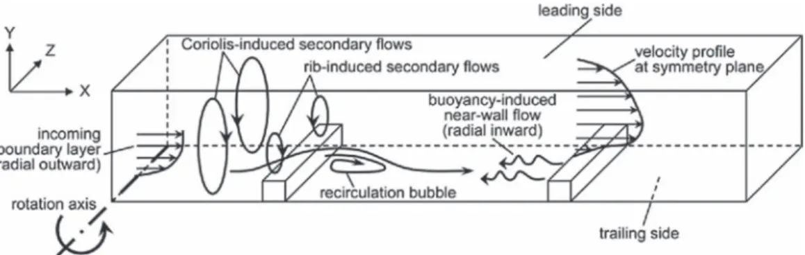
The flow configuration under investigation is schematically sketched in Fig.1, which illustrates the expected flow behavior, based on previous studies. A rectangular channel of nearly square cross-section is provided with ribs along one wall, oriented perpendicularly to the flow direction. The channel is brought to steady rotation around the spanwise axis (i.e., the direction along which the ribs are oriented). The flow is radial outward with respect to the center of rotation. The ribs induce the separation of the boundary layer which, at the relatively large rib spacing considered here and in the well documented non-rotating case, reattaches on the channel floor before facing the next obstacle. The presence of the lateral walls, combined with the streamline curvature forced by the ribs, produces two counter-rotating secondary flow cells. The mean flow features for the non-rotating case are described in detail in literature.22,23 In presence of rotation, Coriolis-induced secondary flow cells appear and superimpose to the rib-induced one. Depending on the rib blockage ratio (rib height over channel height) and rotation regime, one or the other type of secondary flow motion dominates. Moreover, the direction of rotation of the Coriolis-induced secondary flow (in the relative frame) depends on the direction of rotation of the channel (in the absolute frame). The impact of the Coriolis forces is measured by the rotation number:
Ro =ÄD
U0 ,
which is the inverse of the Rossby number, commonly used in geophysical flows, where Ä is the modulus of the angular velocity of the system, U0 is the relative bulk flow velocity, and D is the characteristic length (in this case the channel hydraulic diameter). At the considered rotational regime and blockage ratio (see Sec.IIIfor details) the secondary flow cells due to Coriolis forces are expected to be preponderant over the rib-induced cells. In this case the mean velocity profile in the central part of the channel is skewed as depicted in Fig.1, due to the fact that the fast-moving core of the flow is pushed towards the trailing side of the channel. A more subtle but equally important effect of the Coriolis forces is the stabilization/destabilization of the shear layers: in the present
configuration the impact of this phenomenon is large, especially for the reattachment length and turbulence intensity levels of the separated shear layer past the rib.20
In the present study we consider the case in which the ribbed wall is heated to a temperature level higher than the bulk temperature of the fluid, a situation relevant to internal cooling channels of gas turbine airfoils. A density variation is generated in the near wall layers: the hotter (lower density) fluid close to the wall experiences a weaker centrifugal force with respect to the cooler (higher density) fluid. This situation results in a rotation-induced buoyancy force that drives the local fluid radially inward (Fig.1). The non-dimensional parameter characterizing the effect of rotational buoyancy is the so-called buoyancy number:
Bo = Ro2r
D
Tw−Tf
Tf
, (1)
where r is the radius of rotation, Twis the channel wall temperature, and Tfis the bulk fluid temper-ature. Bo is analogous to the Richardson number Ri = Gr /Re2(where Gr is the Grashof number and Re is the Reynolds number), with the centrifugal acceleration substituting the gravitational one. The nomenclature adopted here is preferred in order to avoid confusion with the rotational Richardson number.24
Several authors focused on the effect of heating one or more of the channel walls at different levels12,25 and found that the influence on the heat transfer was significant. It was conjectured that
this was due to the Coriolis-induced secondary flows, which altered the local coolant temperature by carrying cooler/hotter fluid toward the leading/trailing wall (depending on flow direction and wall heating conditions). Since most studies addressing this issue lack aerodynamic data, it is unclear if the changes of heat transfer levels are also due to an alteration of the flow field. In a further study spatially resolved thermal patterns in a rotating ribbed channel were presented for different wall heating configurations26(heating only the ribbed wall, heating also the opposite wall,
or heating the four walls): the heat transfer distributions appeared altered in absolute level but the pattern was essentially the same for the different cases, suggesting that the main flow features in the vicinity of the ribbed wall remained substantially unchanged when heating the other walls. In the present case only the ribbed wall is heated, the focus being on the local effect of buoyancy on the separating/reattaching flow. This choice is dictated by practical and methodological reasons. Heating all four walls would impede optical access. Heating both leading and trailing walls would cause hot fluid to flow over the lateral wall, which could not be well insulated without compromising the optical access: severe losses would make the thermal boundary conditions uncertain. Heating the wall opposite to the ribbed one would also result in a difficult access for illumination. We shall remark that the present choice of thermal boundary conditions has important consequences on the heat transfer, and possibly on the flow pattern in the buoyant cases, because not heating the three walls causes larger temperature differences with respect to a fully heated channel. However, the intent of the paper is to deepen the understanding of the flow physics at play, rather than reproducing the most realistic industrial application. We therefore chose the thermal boundary condition that could be specified in the most consistent way.
III. METHODOLOGY
A. Experimental installation
The measurements are carried out in a facility designed to perform PIV in rotating channel flows.19It consists of a disk of 2.5 m in diameter which is put in rotation around a horizontal axis by
a DC motor. A centrifugal fan supplies the air which flows through the test section in the outward radial direction. Two-dimensional velocity fields are obtained by means of the on-board PIV system consisting of a 25 W continuous laser diode and a CMOS high-speed camera with an internal memory. The triggering signal for the camera and the electrical power for the instrumentation are transmitted to the rotating frame via a slip ring. A detailed description of the facility can be found in previous publications.19,20 The test section for the present study (Fig.2) consists of a 760 mm long rectangular channel made of Plexiglas, except for the ribbed wall which is machined out of
(a)
(b) X/h
Y h
(c)
FIG. 2. Test section: (a) Schematic sketch, (b) regions of interest and axis definition, and (c) three-dimensional view.
copper. The hydraulic diameter D is 79 mm and the cross-section aspect ratio is 0.9 (75 mm in spanwise direction and 83 mm in wall-normal direction). One wall is provided with 8 ribs of square cross-section, placed perpendicular to the flow direction; their height is h = 8 mm and their spacing is 10h = 80 mm. The Reynolds number based on the bulk velocity U0is Re = U0D/ν =15 000, ν being the air kinematic viscosity. In geometries of this type the major flow features show a certain dependence on the Reynolds number up to Re = 15 000, but they are mostly unaffected by further increase of Reynolds number.27Measurements in rotation are performed at 134 rpm, corresponding
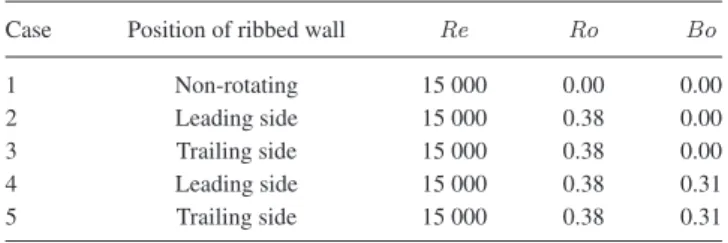
to a rotation number Ro = 0.38. The axis of rotation is parallel to the direction of alignment of the ribs (spanwise direction). The measurement station is at about 1 m from the axis of rotation, therefore in the expression of the buoyancy number, Eq.(1), we have r = 1 m. The facility can rotate in both clockwise and counter-clockwise directions, with the ribbed wall becoming the leading and trailing side, respectively. During the tests addressing the effect of rotational buoyancy, the copper wall is heated by six electric resistances (MINCO) attached to the wall backside and powered through the slip ring by an AC supply located in the fixed frame. Four Pt100 temperature sensors are embedded in the copper wall at different locations spanning the full length. Thermal contact between sensors and copper is guaranteed by using highly conductive paste (OMEGA). Heat losses are minimized by sandwiching the resistances between the copper wall and a 8 mm thick Bakelite slab (thermal conductivity of 0.2 W m−1K−1). The wall temperature is kept constant thanks to a PID (proportional-integral-derivative) controller located on the rotating disk and connected to the Pt100 sensors and the AC supply. The temperature reading is performed in the fixed frame, allowing to monitor spatial and temporal variations of the wall temperature during rotation. Maximum variations along the wall are smaller than 0.5 K and temporal variations during each measurement run are within 1 K. Heating up the ribbed wall at 368 K allows achieving a buoyancy number Bo = 0.31. The power input ranges between 1900 and 2800 W m−2depending on the rotational regime. The inlet flow temperature is measured with a K-type thermocouple. For the hot tests the mean flow temperature in the channel is evaluated from an energy balance, given the mass flow, the power input, and an estimation of the thermal losses. Conduction losses are deemed less than 1% of the power input, and radiation losses about 3%. The five tested flow regimes are summarized in TableI.
TABLE I. Summary of the flow conditions for the investigated cases.
Case Position of ribbed wall Re Ro Bo
1 Non-rotating 15 000 0.00 0.00
2 Leading side 15 000 0.38 0.00
3 Trailing side 15 000 0.38 0.00
4 Leading side 15 000 0.38 0.31
Y h
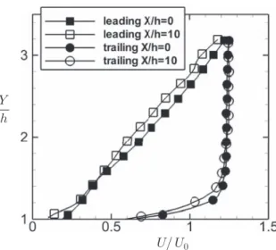
U/ U0
FIG. 3. Streamwise velocity profiles at X/h = 0 and X/h = 10 for buoyant configurations along the leading and trailing walls.
B. PIV measurements
Velocity measurements are performed by PIV along the symmetry plane. The continuous light from the laser diode is redirected by an optical fiber to a compact multi-lense module, which issues a 1 mm thick laser sheet. A magnification factor of about 14 pixels/mm is achieved using a 50 mm objective mounted on the CMOS camera. The PIV processing is realized by means of an iterative interrogation algorithm with windows offset and deformation.28 The final resolution is about 1.3 ×1.3 mm2. The use of an external memory gate connected to the camera allows operating the system in two different modes: for ensemble-averaged measurements and for time-resolved measurements. In the former, one thousand uncorrelated realizations are acquired at 3 Hz and averaged to obtain the mean flow statistics and the two-point spatial correlations. In the latter, 2000 time-resolved realizations are obtained at 3.3 kHz, operating the PIV system in cinematographic mode (i.e., the second image of each pair is the first of the successive pair). These type of data allow to record the spatio-temporal evolution of the flow, and to calculate space-time two-point correlations. The maximum error due to finite sampling is 2% for the mean velocity and 5% for the rms fluctuations, based on a 95% confidence level. Two partially overlapping measurements stations (positions a and b in Fig.2), each about 45 × 30 mm2, cover the area between the 6th and 7th rib, extending in wall-normal direction up to 3.5 rib heights. The Cartesian coordinates X, Y, and Z denote the streamwise, wall-normal, and spanwise directions, respectively, with the origin located at the bottom corner downstream of the 6th rib. The previous study on the non-heated configuration20 showed that the flow was streamwise periodic for both rotating and non-rotating conditions after the 6th obstacle. For the heated cases, full streamwise development cannot be achieved due to the presence of centripetal buoyancy. In fact, because the radius of rotation varies along the test section, the buoyancy number also varies. However, within the investigated area, this variation amounts to about 7% and is deemed to have a minor impact on the flow. As a matter of fact, a direct comparison of streamwise velocity profiles between locations X/h = 0 and X/h = 10 shows marginal streamwised development (Fig.3).
IV. RESULTS
A. Mean flow statistics
In this section the results of the ensemble-averaged single-point statistics are presented. These include the mean velocities and the normal components of the Reynolds stress tensor. The Reynolds shear stresses indicate similar trends with respect to the normal stresses and are not reported. The quantities U (u) and V (v) denote the mean (fluctuating) velocity components along the streamwise direction X and the wall-normal direction Y, respectively. The data are normalized by the rib height h
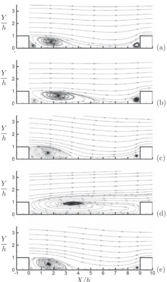
Y h Y h Y h Y h Y h X/h (e) (d) (c) (b) (a)
FIG. 4. In-plane mean streamtracers: non-rotating case (a), non-heated leading side (b), non-heated trailing side (c), heated leading side (d), and heated trailing side (e).
and the bulk velocity U0. Figure4displays the mean in-plane streamtracer patterns in the investigated area for the five considered cases: the non-rotating configuration, the rotating channel with the ribbed wall as leading edge, the rotating channel with the ribbed wall as trailing edge, and the two rotating cases with the ribbed wall heated. In the non-rotating case the typical features of the flow over a rib-roughened wall are visible: the acceleration in the vena contracta, the large recirculation region behind the rib, and the corner vortices at the bottom of the obstacles. When the Coriolis force acts alone it modifies the flow field in the way described in Ref.20: the secondary flows sweep the high momentum core of the coolant towards the trailing side; moreover the stability of the free shear layer generated by the obstacle is altered, resulting in a reduction of the reattachment length along the trailing side, and an extension along the leading side. For the present rotational regime the recirculation, which extends to X/h = 3.75 in the non-rotating case, shrinks down to X/h = 3.45 along the trailing side, while it grows up to X/h = 6 along the leading side. For a lower rotation number (Ro = 0.31) the reattachment along the leading side takes place earlier (X/h = 5.65),20but about the
same location along the trailing side. This confirms that in anti-cyclonic rotation the recirculation asymptotes to a minimum extension.29
Under the action of rotational buoyancy the flow field along the leading side changes completely. The core streamtracers do not follow the usual contraction/expansion pattern over the obstacles. Vice versa, the mean recirculation spans the whole inter-rib region. The corner vortex upstream of the 7th rib has disappeared, absorbed by the larger structure. The size of the recirculation increases also in
FIG. 5. Schematic model for the mean flow streamlining the leading wall, with Coriolis and centripetal buoyancy forces.
wall-normal direction, extending well above the rib height. We remark that the streamtracers in the main recirculation region are spiraling out of the focus; this is true also for the large recirculation in the heated leading wall case. Therefore the Coriolis-induced secondary flows, although they cause significant cross-plane flow, do not invert the fundamental topology of the focus, which remains (along the symmetry plane) a source of mass.
Similar trends were shown by LES calculations21for a similar configuration and flow parameters.
The regime considered in Ref.21was Re = 20000, Ro = 0.3, and Bo = 0.45; the thermal boundary conditions were different with respect to the present case, as the four walls were heated and a uniform heat flux was imposed. Also, both walls were ribbed. However, there is a stark similarity between the streamtracer pattern presented in Fig. 4 of Ref.21and the present results. Those authors considered a number of rotational and heating regimes and showed how, for Bo larger than 0.25, the main recirculation bridged to the following corner vortex, spanning the full inter-rib floor. The structure moved downstream for higher buoyancy number. Indeed, at their Bo = 0.45, the center of the recirculation is located further downstream than in the present case. They argued that this larger recirculation is responsible for the increase in heat transfer level found in experiment in similar geometries for Bo > 0.25.30
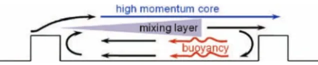
Concerning the underlying mechanism behind this flow pattern, a schematic model is depicted in Fig. 5: the rib-roughened wall heats up the adjacent fluid layers, which are driven upstream by centripetal buoyancy (this condition is also referred to as opposing buoyancy, because it acts in direction opposite to the main flow direction). The reverse flow interacts with the main stream flowing above the ribs, creating a buoyant mixing layer. Due to the reverse flow spanning the whole floor, the mixing layer is not curved towards the wall as in the non-buoyant rotating case, but is sustained until the next rib. Approaching the obstacles the streamtracers bend, bridging both streams and creating the recirculating path. The source point at the center of the recirculation highlights the three-dimensional nature of the flow, which can be captured only partially by the present planar technique. Nevertheless, as the measured velocity field lies on the symmetry plane, it is expected to capture the main dynamics in the considered configuration.
It is worth noting that wall-mounted obstacles placed at the considered spacing are usually considered as k-type roughness.31 In this type of roughness the main recirculation downstream of
the ribs occupies only a fraction of the space in between the elements. However from Fig.4it is evident that the opposing buoyancy produces a mean flow pattern rather reminiscent of the d-type roughness, with a single recirculation spanning the full inter-rib floor.
Another significant aspect of Fig.4is the very limited effect of buoyancy on the flow field along the trailing wall. In fact, based on the LES simulation of a ribbed channel flow in a similar regime, it has been argued that, for radial outward flows in rotating heated channels, the fluid adjacent to the trailing wall experiences aiding buoyancy:32 when the cool core of the flow is pushed towards the
hot trailing wall, since it has lower density than the neighboring fluid, it experiences a centrifugal (aiding) buoyancy. In the present case it is expected that the cooler core mixes rapidly with the hotter near-wall fluid, also due to the strong turbulence fluctuations along the trailing wall (see Fig.7below), smoothing out the temperature and density gradients, and reducing the local radial acceleration (either aiding or opposing). Also, it should be noted that the flow along the trailing side of the channel is significantly faster than along the leading side, due to the Coriolis-induced secondary flows. It is likely that the shorter residence time of the fluid layers in the proximity of the hot wall limits their increase in temperature, and so the effect on the flow is also limited.
Further understanding of the flow can be gained considering the in-plane mean velocity contours. Considering the streamwise velocities, Fig.6(left), it is apparent how the Coriolis-induced secondary flows increase the through-flow velocity along the trailing side, and vice versa along the leading
X/h X/h Y h Y h Y h Y h Y h (e) (d) (c) (b) (a)
FIG. 6. (Left) Contours of streamwise mean velocity component: heated leading wall (a), rotating wall (b), non-heated trailing wall (c), non-heated leading wall (d), and non-heated trailing wall (e). (Right) Contours of wall-normal mean velocity component: non-heated leading wall (a), non-rotating wall (b), non-heated trailing wall (c), heated leading wall (d), and heated trailing wall (e).
side. The shrinking of the recirculation region along the trailing side results in a more abrupt expansion, whereas on the leading side the vena contracta effect is less pronounced, and streamwise accelerations are reduced. On the leading side the centripetal buoyancy drives upstream the hot fluid adjacent to the wall, creating a continuous reverse flow from the 7th rib to the 6th. The mean flow resembles closely (at least in the investigated plane) a two-dimensional mixing layer between two counter-current streams. Buoyancy does not appear to alter significantly the streamwise velocity along the trailing side. Figure6 (right) shows the wall-normal component of the mean in-plane velocity: the Coriolis force produces an intense downwash motion along the trailing wall after the 6th rib, and a strong upward deflection of the streamtracers just before the 7th rib. Along the leading wall the wall-normal component is largely damped, and even more so when buoyancy is active: in this case V is large only in the vicinity of the ribs, where the blockage imposed by the obstacles forces the streamtracer to turn abruptly. Along the trailing side the effect of buoyancy results in smaller wall-normal velocity (in absolute value), although the differences with respect to the non-heated case are negligible.
B. Reynolds stresses
Rotation alters the mean flow pattern as well as the turbulence properties. The strong impact of the Coriolis force on the streamwise and wall-normal fluctuations in the considered channel geometry was demonstrated for a lower rotation regime:20 along the rib-roughened trailing wall the destabilizing effect of rotation augments turbulent activity in both X and Y directions, and
X/h X/h Y h Y h Y h Y h Y h (e) (d) (c) (b) (a)
FIG. 7. (Left) Contours of streamwise Reynolds stresses: non-heated leading side (a), non-rotating case (b), non-heated trailing side (c), heated leading side (d), and heated trailing side (e). (Right) Contours of wall-normal Reynolds stresses: non-heated leading side (a), non-rotating case (b), non-heated trailing side (c), heated leading side (d), and heated trailing side (e).
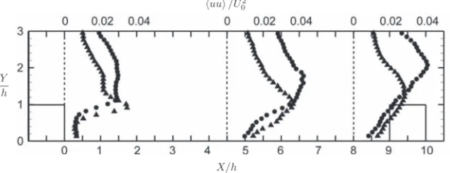
vice versa for the leading wall. This is illustrated for the present case in Fig.7(left), displaying the normal components of the Reynolds stress tensor along X and Y directions. It is particularly evident how rotation affects the turbulent fluctuations in the free shear layer behind the rib. With rotational buoyancy the distributions of both Reynolds stress components are significantly altered along the ribbed leading wall. Both huui and hvvi are damped in the region downstream the 6th rib and enhanced approaching the 7th rib. This is clearly shown in Fig.8, that presents profiles of
uu /U2 0
X/h Y
h
FIG. 8. Profiles of streamwise Reynolds stresses extracted at X/ h = 0, 4.5, and 8, for the non-heated leading wall (triangles) and heated leading wall (circles).
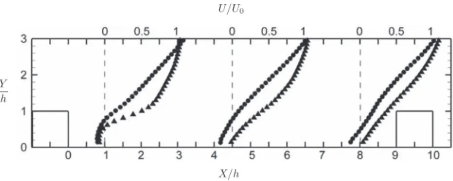
U/U0
X/h Y
h
FIG. 9. Profiles of streamwise mean velocity extracted at X/ h = 0, 4.5, and 8, for the non-heated leading wall (triangles) and heated leading wall (circles).
streamwise normal stresses at three locations along the leading wall, for both heated and non-heated cases. The marked peak in turbulence activity right downstream of the rib in the non-heated case becomes much milder with streamwise development. Vice versa, in the heated case, the turbulence intensity grows gradually and largely exceeds the levels of the non-heated wall in the downstream half of the inter-rib space. The origin of this trend is found in the different development of the shear layer past the obstacle. Figure9shows profiles of streamwise velocity at the same locations of the profiles in Fig.8, for both the heated and non-heated leading walls. In the non-heated case the local velocity gradient above the recirculation is high, but it diminishes significantly as the vena contracta re-expands. Instead the shear associated to the heated case is maintained almost constant across the domain, due to the reverse flow spanning the whole inter-rib space. In the non heated wall, both shear and, consequently, turbulence levels are elevated in a relatively confined region (Y/h < 1.5). On the other hand, the heated case shows a consistent level of turbulence much further into the core of the flow. This considerations are further supported by Fig.10, showing profiles of huui at Y/h = 3 for all considered cases (except the heated trailing wall, negligibly different from the non-heated case). Remarkably, both the rotating non-heated cases have lower turbulence intensity than the stationary case. Along the leading wall, the turbulence agitation is quenched by the stabilizing action of the Coriolis force. Along the trailing wall, although the turbulence intensity is much higher for Y/h < 1.5, the secondary flows push the fluid along the symmetry plane towards the ribbed wall, and somewhat confine the turbulence activity to the near-wall region. Vice versa, along the heated leading wall the streamwise Reynolds stresses grow steadily as the shear layer develops, and above the downstream obstacle they reach similar levels as in the steady case. We shall notice that, unlike the other cases, the turbulence along the heated leading wall appears far from being developed (as indicated by the lack of streamwise periodicity of huui in streamwise direction). Therefore even higher levels of turbulence activity may be expected further downstream.
X/h uu
U2 0
FIG. 10. Profiles of streamwise Reynolds stresses extracted at Y/h = 3, for the non-rotating case (squares), the non-heated leading wall (triangles), the non-heated trailing wall (diamonds), and the heated leading wall (circles).
Finally, we remark that the near-wall flow reversal caused by rotational buoyancy inverts the direction of the Coriolis force acting on this fluid layer: considering the direction of the local shear, the Coriolis force is expected to have a destabilizing effect. Although the Reynolds stress levels are found to be low in the immediate proximity of the heated leading wall, the local mean velocity is also very low. It is difficult to infer whether, in absence of Coriolis force, the turbulence intensity would be larger or smaller for an analogous flow pattern.
As in the mean velocity fields, along the trailing side the changes in turbulence structure due to buoyancy are minor: for both huui and hvvi the highly turbulent plume is somewhat longer for the heated wall. Similar conclusions with respect to the above are drawn from the distributions of Reynolds shear stresses huvi, which are not reported here for sake of brevity.
These findings substantially confirm the conclusions of a previous study,21 where a similar configuration was investigated. In the remainder of the paper we attempt to elucidate some of the dynamics underlying the above single-point statistics, also leveraging the time-accurate velocity measurements.
C. Proper orthogonal decomposition
In order to highlight the characteristic flow motions in the considered cases, we use the POD method. This projects an ensemble of N samples of a vector field variable u = (u(x, t ), v(x, t )), onto N orthogonal spatial modes ϕn(x). An introduction to the technique can be found in Ref.33. By taking advantage of the PIV setup leading to a snapshot technique,34the eigenvalue problem is
rewritten as
Z
hu(x, t ) · u(x, t )ian(t′)dt′=λnan(t ),
where h · i is the spatial autocorrelation, an(t) are the time-varying amplitude coefficients, and λ n are the eigen values which represent the energy content of each mode n. Once these are obtained, the POD modes ϕn are then retrieved by projecting the time-varying coefficients onto the original data ensemble using
ϕn(x) = 1
N λn Z
an(t )u(x, t )dt.
The POD modes, ordered according to their respective eigenvalues, provide an optimal basis for expansion of the flow, because they capture more energy than any other basis. Therefore, we associate the most energetic modes with large-scale, energy-containing structures in the present flow.
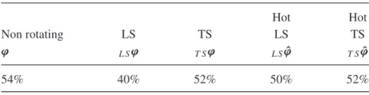
TableIIshows the cumulative energy contained in the first eight POD modes for the various cases. Considering that this is about half of the total energy, POD is expected to capture many of the important aspects of the unsteady motion.
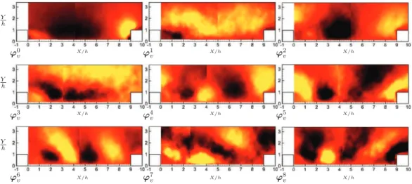
We begin the POD analysis by illustrating the most energetic modes of the non-rotating case. The first eight modes are reported in Fig.11, together with the mean flow field (the zeroth mode). The wall-normal velocity component is considered here, as it illustrates more clearly some of the salient flow features and the differences among the various cases. Since the amount of energy contained in each mode varies, the color scale is adjusted to display clearly the structures in each figure. In order to compare the intensity of the various modes, their fractional energy content is plotted in Fig.12.
TABLE II. Cumulative energy of the first eight POD modes for the various cases: non rotating, leading side and trailing side, buoyant (hot wall) and non-buoyant.
Hot Hot
Non rotating LS TS LS TS
ϕ L Sϕ T Sϕ L Sϕˆ T Sϕˆ
ϕ0v ϕ1v ϕ2v ϕ3v ϕ4v ϕ5v ϕ6v ϕ7v ϕ8v Y h X/h X/h X/h Y h X/h X/h X/h Y h X/h X/h X/h
FIG. 11. Mean flow and first eight POD modes of the wall-normal velocity component in the non-rotating case. These modes represent 54.7% of the total energy.
The first mode describes a motion that spans the whole inter-rib domain. This is consistent with the results of a recent study dedicated to this geometry in a non-rotating frame:23 the separated shear layer past the rib grows up to the following obstacle, and its flapping produces large scale motions which persist for the entire inter-rib region and beyond. Further modes indicate the multi-scale nature of the flow, with large energetic features breaking down into smaller, less energetic ones. The eighth mode shows an alternation of upward and downward motions, with size of the order of the rib height, traveling downstream. This is again consistent with the picture of the flow gathered for this baseline non-rotating case.23
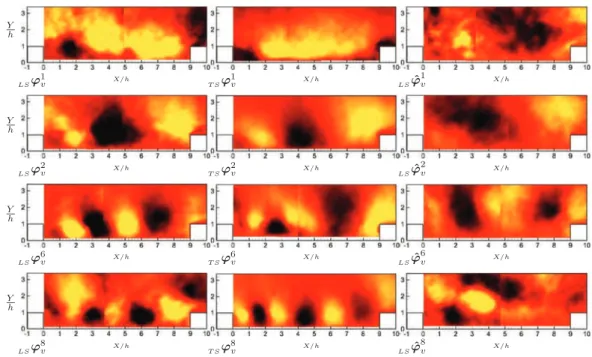
The effects of Coriolis and buoyancy forces, clearly visible in the single-point statistics in Fig.7, are reflected in the energy-containing modes. Figure13shows representative modes (first, second, sixth, and eighth) for the non-heated leading side, non-heated trailing side, and heated leading side. Once again, the heated trailing side does not possess significantly different features with respect to the non-heated case, and therefore is not shown. These modes are chosen to illustrate both the large energetic motions of the primary modes, and the smaller features of the further modes. The distribution of the energy content among the modes for the rotating cases is very similar to the one shown in Fig.12. The first mode in the non-heated rotating cases indicates an extended motion spanning the entire domain. With respect to the non-rotating case, the size of the downward motion past the rib is larger or smaller depending on the sense of rotation. This is related to the size of the recirculation region, which shrinks along the trailing wall and increases along the leading
fr a ct io n a l en er g y Mode number
LSϕ 1 v T Sϕ 1 v LSϕˆ 1 v LSϕ 2 v T Sϕ 2 v LSϕˆ 2 v LSϕ 6 v T Sϕ 6 v LSϕˆ 6 v LSϕ 8 v T Sϕ 8 v LSϕˆ 8 v Y h X/h X/h X/h Y h X/h X/h X/h Y h X/h X/h X/h Y h X/h X/h X/h
FIG. 13. First, second, sixth, and eight POD modes of the wall-normal velocity component: non-heated leading side (left column), non-heated trailing side (middle column), and heated leading side (right column).
wall. At higher modes the flow structures are located closer to the wall when this corresponds to the trailing side. This is a consequence of the Coriolis-induced secondary motions, that push the core of the flow towards the trailing wall (Fig.1). The opposite is true for the leading wall. These structures appear slightly smaller along the trailing wall. This is in agreement with the view suggested by the instantaneous realizations and two-point correlations of swirling strength20for the
same configuration and at similar rotation regimes.
For the heated leading side, the first mode reveals strongly different features with respect to the other cases. The first mode does not span the full inter-rib domain and it appears more blurred, suggesting that the shear layer is associated to a less energetic oscillation in wall-normal direction. The further modes show very different patterns from the non-heated cases, and indicate the presence of elongated structures in streamwise directions, rather than an alternation of compact structures shed from the shear layer.
D. Spatio-temporal evolution of the flow structures
So far we have reported ensemble-averaged quantities, based on statistically independent real-izations. However the separated turbulent flow under consideration is expected to be characterized by coherent structures.33The latter leave a footprint on the flow statistics, as they contribute critically to both to the production and transport of turbulent energy. In order to characterize these structures we will use the temporally resolved velocity fields. We are especially interested in the length scales and time scales of the vortical coherent structures, and their advection velocity. Since the flow separation and reversal is a signature feature of the present configuration (and is known to have major influence on the heat transfer at the wall), we also analyze the temporal evolution of the separated/reverse flow regions.
The time-resolved stack of acquired 2D velocity fields constitutes a three-dimensional set of data, where the third dimension is the time T. In the XYT space, XY planes correspond to PIV realizations, while XT and YT planes provide spacetime diagrams, which are presented in the following. This fashion of presenting the temporal evolution of two-dimensional velocity fields was described in greater detail in Ref.23. In this section, for ease of representation, only 400 consecutive realizations (out of the 2000 acquired) will be visualized, corresponding to about 42 time units h/U0. They are
(a) (b) (c) (d) T U0/h X h X h X h X h
FIG. 14. Space-time diagrams of velocity fluctuations at Y/h = 1.2, for the non-heated leading wall (a), non-rotating wall (b), non-heated trailing wall (c), and heated leading wall (d).
however representative of the trends found in the entire XYT volume recorded. The data for the heated trailing wall are not reported, as they closely follow the trends of the corresponding non-heated case. Figure 14 displays contours of streamwise velocity fluctuations over a streamwise section at Y/h = 1.2, i.e., along the shear layer past the rib. The fluctuations are obtained subtracting the ensemble-averaged velocity field from the time-resolved data set. The alternation of streaks of positive and negative fluctuations indicates that the shear layer is flapping, as expected in the separated flow downstream of the obstacle.23The inclination of the streaks in the XT plane is related
to the advection velocity of the structures. For the non-rotating case, there appear to be mainly two classes of events: negative u fluctuations traveling at slower velocity than the local mean velocity (about 0.4U0versus 0.6U0), and positive u fluctuations traveling at significantly higher velocity (up to 0.85U0). A very similar trend is found in the non-heated leading wall case, with the intensity of the fluctuations being lower due to the inhibited turbulence levels, and the advection velocity being smaller due to the lower local mean velocity. The large range of velocity scales suggests that some of the events are generated locally by the rib-boundary layer interaction, while others are the signature of structures traveling from rib to rib.23For the non-heated trailing wall case, besides noticing that
the fluctuations are more vigorous, we remark that both the positive and negative u structures move with approximately the same velocity as the local mean flow (about 0.9U0). This would suggest that the rib-to-rib interaction is weakened in this case; support to this deduction is provided below. Finally, the heated leading wall case displays a much slower (and milder) alternation of positive and negative fluctuations, suggesting that the shear layer flapping is modulated by a lower frequency with respect to the other cases.
(a) (b) (c) (d) T U0/h Y h Y h Y h Y h
FIG. 15. Space-time diagrams of velocity fluctuations at X/h = 3, for the non-heated leading wall (a), non-rotating wall (b), non-heated trailing wall (c), and heated leading wall (d).
Figure15shows contours of wall-normal velocity on a wall-normal section at X/h = 3. The flow along the trailing wall presents major downwash events that extends over 3 rib heights, and impinge on the inter-rib floor with high vertical velocity. The downwash motions in the non-rotating case and in the non-heated leading wall case are less abrupt. Again, with respect to the other cases, the heated leading wall experiences relatively slow and mild vertical velocity fluctuations.
Figure16depicts the streamwise velocity just above the tip of the 7th rib (Y/h = 1.1). For the non-heated leading wall the near-wall flow is mostly directed forward, but mild and long-lasting flow reversals may occur. In the non-rotating case, the frequent and intense reverse flow events suggest the presence of intermittent recirculation, which at times can span the whole tip surface. This recirculation is seen often in instantaneous realizations, but its high unsteadiness (and small wall-normal extension) prevents from seeing its footprint on the ensemble-average field. Along the non-heated trailing wall the reverse flow displays an even more irregular behavior: backflow occurs over very short periods and very sporadically. Over the ribs of the heated leading wall flow reversal is unlikely to happen, mostly because of the completely altered flow topology with respect to the non-heated cases.
In order to describe the behavior of the reverse flow, Figs.17 and 18 show isosurfaces at
U/U0 = −0.1 in the XYT volume, colored by wall-normal distance, for positions a and b, respec-tively. In Fig.17(downstream of the 6th rib), the non-rotating and the non-heated leading wall cases present again somewhat similar features, especially concerning the wall-normal extent of the recir-culation. The instantaneous bubble extends further downstream in the latter case than in the former, consistently with the larger time-average recirculation. Also, while the bubble along the non-heated leading wall is fairly persistent in time, the non-rotating case shows strong intermittency, with the reverse flow region shrinking or even disappearing at times (at the chosen threshold). This can be interpreted as an oscillation of the reattachment point, although even the definition of instantaneous reattachment is not trivial, due to the multiple structures arriving on the wall at any given time.
(a) (b) (c) (d) T U0/h X h X h X h X h
FIG. 16. Space-time diagrams of velocity fluctuations at Y/h = 1.1, for the non-heated leading wall (a), non-rotating wall (b), non-heated trailing wall (c), and heated leading wall (d).
Such unsteady behavior is even more pronounced along the non-heated trailing wall, which indeed is characterized by much higher turbulence levels. In this case the bubble is not only shorter in streamwise direction, but also confined to smaller wall-normal distances, as a consequence of the core of the flow pushing towards the ribbed wall. Along the heated leading wall, the reverse flow is much larger than for the other cases, both in X and Y directions, as expected from the mean flow pattern. Also it is confirmed that the reverse flow is modulated by a low frequency motion.
In Figure 18, the U/U0 = −0.1 isosurface highlights the recirculation upstream of the 7th rib. In the non-rotating and non-heated leading wall cases, there is a persistent flow reversal over most of the displayed temporal sequence, confined at the corner between the rib and the floor. This highlights the continuous presence of the recirculation structure generated by the separation of the flow approaching the obstacle. In the non-heated trailing wall case, there is rather a sporadic bursting of reverse flow events. This reflects the state of the highly turbulent flow streamlining the bottom wall and approaching the rib. On the other hand, along the heated leading wall there is again a massive flow reversal over the whole temporal segment. Combined with the picture provided by position a, we conclude that this reverse flow region is a continuous feature, constantly spanning the whole inter-rib floor. The upper portion of the isosurface appears quite beveled, probably due to the development of the free shear layer that grows more turbulent in streamwise direction.
We now turn our attention to the coherent vortical structures, which play a major role in turbulent flows as they carry a significant fraction of Reynolds stresses, vorticity, and production of turbulent kinetic energy. Along the investigated symmetry plane a large portion of the vortices are expected to be oriented spanwise, and 2D-PIV is a suitable tool for detecting such structures. Streamwise vortices
(a) (b) (c) (d) X/h X/h X/h X/h T U0/h T U0/h T U0/h T U0/h Y h Y h Y h Y h
FIG. 17. Isosurface of instantaneous velocity U/U0= −0.1 in the space-time volume recorded at position a, for the non-heated
leading wall (a), non-rotating wall (b), non-heated trailing wall (c), and heated leading wall (d).
play also an important role in the dynamics of the separating/reattaching flow, but they can hardly be captured by planar PIV. Therefore we confine our analysis to the spanwise vortical structures. To identify the vortex cores, we evaluate the swirling strength λci, i.e., is the imaginary part of the locally calculated complex conjugate eigenvalues of the velocity gradient tensor.35Figures19and
20display three-dimensional views of isosurfaces of swirling strength in the space-time domain, for positions a and b, respectively. This plotted values correspond to 10% of the maximum swirling strength (in absolute value). Vortices that have positive vorticity (rotating counter-clockwise in the
XY plane) are coloured in red, whereas vortices with negative vorticity (rotating clockwise) are coloured in blue. Unlike point-wise measurements or uncorrelated PIV realizations, the present approach provides an indication of both spatial and temporal coherence of the structures. We can
(a) (b) (c) (d) X/h X/h X/h X/h T U0/h T U0/h T U0/h T U0/h Y h Y h Y h Y h
FIG. 18. Isosurface of instantaneous velocity U/U0= −0.1 in the space-time volume recorded at position b, for the non-heated
leading wall (a), non-rotating wall (b), non-heated trailing wall (c), and heated leading wall (d).
observe how vortices travel in space-time, pairing frequently to form larger structures. As expected, a majority of clockwise rotating vortices are found, due to the mean shear of the separated flow. The clockwise vortices originate probably from streamwise structures in the separated turbulent flows, which are tilted towards the spanwise direction by the secondary flows. Fast-moving structures are observed above the rib height, carried by the main stream, while near the floor vortical structures are moving slower or even remain at the same location (as they appear aligned with the time axis). Along the non-heated leading wall the vortices move slower, reflecting the lower velocity of the flow past the ribs. The stabilizing effect of rotation on the shear layer results in well-defined vortex cores, that travel for long distance in space and time without losing coherence. Along the non-heated trailing wall, the spanwise vortices travel faster due to the higher velocity levels, but the structures are quickly disrupted by the three-dimensional turbulent motion excited by the destabilizing rotation.
(a) (b) (c) (d) X/h X/h X/h X/h T U0/h T U0/h T U0/h T U0/h Y h Y h Y h Y h
FIG. 19. Vortical structures identified by isosurfaces of swirling strength (10% of maximum value) in the space-time volume recorded at position a, for the non-heated leading wall (a), non-rotating wall (b), non-heated trailing wall (c), and heated leading wall (d).
(a) (b) (c) (d) X/h X/h X/h X/h T U0/h T U0/h T U0/h T U0/h Y h Y h Y h Y h
FIG. 20. Vortical structures identified by isosurfaces of swirling strength (10% of maximum value) in the space-time volume recorded at position b, for the non-heated leading wall (a), non-rotating wall (b), non-heated trailing wall (c), and heated leading wall (d).
In this case, unlike on the non-rotating and the non-heated leading wall, no coherent vortex appear to survive up to the following rib, disrupted by the high shear and by the strong background turbulence. This confirms that the trailing wall case is the most unlikely to show rib-to-rib interaction. Along the heated leading wall, the rotational buoyancy pushes the flow upstream, drastically reducing the velocity at which the vortices are advected downstream. Actually, in the region close to the wall the
vortical structures appear to travel upstream, following the mean recirculation that spans the whole inter-rib region. The structures along the heated leading wall are even more persistent than in its non-heated counterpart, especially in position a, where the lowest turbulence levels are found.
E. Two-point correlations
In order to highlight the statistical footprints of the instantaneous flow features, we consider the streamwise two-point velocity correlation function:
Ruu(X0, 1X) = u(X0)u(X0+1X) q u(X0)2 q u(X0)2 , (2)
where X0is the position vector of a fixed reference point, and 1X is the distance vector between a moving point and the reference point. Here the overbar indicates the ensemble-average over 1000 uncorrelated PIV realizations. Contours of Ruu(X0, Y0; X, Y) at three reference points are displayed in Fig.21for the various cases. In order to focus on the evolution of the free shear layer and on the recirculation upstream of the rib, the reference points are chosen as: (X0/h, Y0/h) = (1, 1.2), (4.5,
Y h Y h Y h Y h X/h (a) (b) (c) (d)
FIG. 21. Contours of two-point correlation of streamwise velocity at location (X0/h, Y0/h) = (1, 1.2), (4.5, 1.1), and (8, 0.5),
1.1), and (8, 0.5). Contours below Ruu=0.4 are blanked, marking a conventional extent of the large scale motions at each reference point. Along the non-heated leading wall the length scales are much smaller than in the non-rotating case, especially in the developed free shear layer, suggesting that the reduced turbulence activity limits the area affected by the spanwise rollers and by the flapping of the shear layer. The non-heated trailing wall case shows similar Ruu contours to the non-rotating case, but the orientation of the pattern downstream of the 6th rib is influenced by the fact that the core of the flow pushes towards the ribbed wall. The opposite trend is observed along the heated leading wall, where the large extension of the recirculation bubble in Y direction accounts for the increased size of the correlated region with respect to its non-heated counterpart, especially in the early phases of the shear layer. Remarkably, in the non-rotating case, unlike in all the other configurations, the recirculation upstream of the 7th rib is correlated to large scale motions above the obstacle. This is likely a consequence of the large scales associated to the flow that impinge on and overtake the rib, and could have consequences on the local heat transfer. The other case with equally large length scales is the non-heated trailing wall, but the high turbulence levels may disrupt the space-time coherence of the recirculation (see Fig.18).
Having a spatio-temporal data set allows to compute space-time correlations. In order to add statistical relevance to the previous considerations about the vortical structures, we calculate space-time two-point correlations of the swirling strength as
Rλλ(X0, 1X, 1T) = λci(X0,T0)λci(X0+1X, T0+1T) q λci(X0,T0)2 q λci(X0,T0)2 , (3)
where T0 is a reference time and 1T0 is the time delay with respect to T0. The overbar indicates average over 2000 time-resolved realizations. Since the considered turbulent process is stationary (in the mean sense) the correlation coefficient is independent of T0. Figure22displays isosurfaces of Rλλ=0.5 for the reference point (X0/h, Y0/h) = (1, 1.2). The latter is chosen because is close to the maximum of turbulence intensity for all non-heated cases. The selection of different points in the shear layer does not affect the global trends. The value Rλλ=0.5 is taken as a conventional definition of length and time scale of the spanwise vortices, marking the region of the spatio-temporal domain where the swirling events are strongly correlated with the one happening at (X0, Y0). As one can
∆T U0 h ∆T U0 h ∆X/h ∆X/h (a) (b) (c) (d)
FIG. 22. Isosurfaces of two-point space-time correlation of swirling strength (Rλλ=0.5) at location (X0/h, Y0/h) = (1, 1.2),
TABLE III. Advection velocities of spanwise vortical structures and corre-sponding mean flow velocities at the location (X0/h, Y0/h) = (1, 1.2) for the
different cases.
Configuration Advection velocity Local mean velocity
Non-rotating 0.59 U0 0.72 U0
Non-heated leading wall 0.42 U0 0.60 U0
Non-heated trailing wall 0.90 U0 1.13 U0
Heated leading wall 0.30 U0 0.27 U0
see, the destabilizing effect of rotation along the trailing wall reduces the space-time coherence of the spanwise vortices shed from the rib, diminishing dramatically both length and time scale of the swirling structures. The opposite is true for the leading wall. When rotational buoyancy is acting, the length scale and even more the time scale of the vortices are greatly increased. This is due to the reduced transverse velocity gradient in the mixing layer: shear can stretch and tear the vortices apart unless they are at least as strong as the shear itself. The high shear in the trailing wall case reduces the lifetime of the vortices, while in the leading wall case the milder shear (especially for the heated case) allows the vortices to survive longer. The slope of the isosurface pattern in the 1X − 1T plane corresponds to the local advection velocity, i.e., the velocity at which the vortical structures are advected by the flow (in streamwise direction). These velocities are listed in TableIIIfor the different cases, and compared to the mean flow. For the non-heated cases the advection velocities are found to be significantly slower than the local mean flow (between 18% and 30%), while for the heated leading wall the coherent vortical structures move 10% faster than the local mean flow. The fundamentally dissimilar topology and possibly the density variations along the heated leading wall are deemed responsible for this qualitative difference, although the specific mechanisms responsible for the trend are not obvious.
V. CONCLUSIONS
We have investigated the turbulent flow in a rotating ribbed duct by means of particle image velocimetry. By heating the rib-roughened wall, temperature and density gradients are produced in the air flow, resulting in significant effects of the centrifugal force on the velocity field. The direction of the flow is radial outward, which causes a centripetal buoyancy force acting on the near-wall layers of fluid heated by the wall. There is a strong coupling between Coriolis and buoyancy forces: depending on the sense of rotation, the Coriolis force causes secondary flows that either increase or decrease velocity and turbulence intensity of the fluid flow near the heated wall. In the latter case, the buoyancy leads to flow reversal in the near wall region, inverting the sense of the Coriolis force. A precise breakdown of the various contributions and reciprocate influences would require a detailed budget of the turbulence production, but to this end we would need the instantaneous temperature/density information, which is challenging to obtain.
However, the coupling between Coriolis and buoyancy is demonstrated by the fact that the classical picture of separating and reattaching in between the obstacles is modified substantially, far beyond the effect of the Coriolis force alone. At the considered regime, along the leading wall the recirculation region extends over the whole inter-rib distance, and grows even in wall-normal direction much beyond the obstacle height. This flow pattern results from the interaction of the core flow with the near-wall fluid directed upstream, creating a quasi-planar mixing layer. The hot fluid is pushed from the near-wall layers into the coolant core and, vice versa, the hot fluid near the wall is injected into the main stream, in a process that greatly enhances the mixing. We also observe that, with respect to both non-heated rotating cases, the buoyant flow along the leading wall is associated with a higher turbulence intensity in the region of the developed shear layer that grows toward the core of the flow. The combination of these factors contributes to the improvement in heat transfer along the heated leading wall, found by thermal measurements for similar geometries and regimes.
These conclusions are in line with the results of the LES simulations21in a similar configuration at
comparable flow regimes, which up to now had not been confirmed by experiments.
Along the trailing wall the effect of rotational buoyancy does not impact the flow in a sizeable manner. This is the consequences of two facts: the flow is more turbulent due to the destabilizing action of the Coriolis force, and the consequent high mixing smoothes out local density variations. Also, the near-wall velocity is higher due to Coriolis-induced secondary flows, and therefore the residence time of the fluid in the vicinity of the heated wall is shorter, limiting its temperature rise.
Characteristic flow motions are extracted by proper orthogonal decomposition, confirming the features previously deduced by the authors in the non-rotating case and in the rotating case with unheated walls: large scale motions about the size of the obstacles are created in the separated shear layer, and advected downstream. Along the heated leading wall, the most energetic modes show that the flow is characterized by a very long wavelength of large-scale streamwise motion. This is confirmed by the inspection of the time-resolved velocity fields, visualized in the space-time volume: the reverse flow region is shown to be a persistent feature, continuously spanning the whole inter-rib floor and mildly modulated by a low frequency oscillation. The latter is especially visible in the flapping of the shear layer, imaged along space-time diagrams. Since the flow along the heated leading wall presents a d-type topology, it is possible that temporal fluctuation of the large “bubble” is controlled by the inter-rib distance (whereas in the other configurations the rib height is the controlling length scale). Further investigation is warranted in this direction. In the non-buoyant cases the time-dependent behavior of the recirculation bubble is more intermittent (especially along the trailing wall) resulting in large oscillations of the instantaneous reattachment point. Along the trailing wall the high shear and the strong background turbulence disrupt the spanwise vortical structures generated in the separated shear layer, which die before reaching the next obstacle. On the other hand, in the non-rotating case and in the leading wall cases many vortical structures maintain their coherence as they are advected downstream, and may interact with the flow separating above the following rib.
The spatial extension of the large scale motions is strongly affected by the stabiliz-ing/destabilizing effect of the system rotation. The alteration of the flow field caused by rotational buoyancy has the consequence of expanding the large scale motions through the shear layer, which results in a better mixing also in a non-local sense. The space-time two-point correlation centered in the shear layer indicates that the non-heated leading wall case produces larger and more robust spanwise rollers, while the opposite is true for the non-heated trailing wall. The flow along the heated leading wall, with its mild but consistent shear and limited unsteadiness, produces the largest and most persistent vortices, which contribute to the transport and mixing. For all non-heated cases, and irrespective of rotation, such vortical coherent structures are advected with velocity significantly lower than the local mean flow; vice versa along the heated leading wall they move somewhat faster than the local mean flow. The present regime, characterized by mixing convection coupled with rotation, represents a challenge for classic turbulence closure schemes. To date, calculations of such flows could only be verified with the aid of thermal measurements at the wall (which do not give sufficient confidence about the robustness of the flow solution), or by high fidelity simulations (which however require validation). The reported measurements represent the first experimental flow field data in a duct flow with rotational buoyancy, and therefore they should be useful to the modelers. In view of high-fidelity, time-accurate simulations, the reported behaviors, and their interpretation should help discerning whether the spatio-temporal evolution of the flow is accurately reproduced.
ACKNOWLEDGMENTS
The first author was financially supported by Turbomeca (SAFRAN Group). The contribution as well as the permission to publish the data are gratefully acknowledged. The technical support and expertise of Julien Desset, Terence Boeyen, Walter Sgalbiero, and Pierre Londers was highly appreciated.
1J. P. Johnston, R. P. Halleen, and D. K. Lezius, “Effects of spanwise rotation on the structure of two-dimensional fully