Strong and tough metal/ceramic micro-laminates
Claudio Ferraroa*, Sylvain Meilleb, Julien Réthoréc, Na Nia, Jerome Chevalierb, Eduardo Saiza a Department of Materials, Centre of Advanced Structural Ceramics, Imperial College London, London SW7 2AZ, UK
b Univ. Lyon, MATEIS, INSA de Lyon, UMR CNRS 5510, Lyon, France
c Research Institute in Civil and Mechanical Engineering (GeM), Ecole Centrale de Nantes, Université de Nantes, UMR6183 CNRS, Nantes, France
*Corresponding author: [email protected], +44 (0) 72522615226, Department of Materials, Centre of Advanced Structural Ceramics, Imperial College London, London SW7 2AZ, UK Keywords: Freeze-casting; Alumina; Aluminium alloy; Infiltration; Composites
Abstract
There is a growing interest in the development of composites with complex structures designed to generate enhanced mechanical properties. The challenge is how to implement these structures in practical materials with the required degree of control. Here we show how freeze casting of ceramic preforms combined with metal infiltration can be used to fabricate Al2O3/Al-4wt% Mg micro-laminated composites. By manipulating the solid content of the suspension and the morphology of the ceramic particles (from platelets to round particles) it is possible to access a range of structures with layer thickness varying between 1 to 30 m and metallic contents between 66 to 86 vol.%. The mechanical response of the materials is characterized by combining bending tests with observation of crack propagation in two and three dimensions using different imaging techniques. These composites are able to combine high strength and toughness. They exhibit a rising R-curve behaviour although different structures generate different toughening mechanisms. Composites fabricated with Al2O3 particles exhibit the highest fracture resistance approaching 60 MPa.m1/2, while laminates prepared from Al2O3 platelets exhibit higher strengths (above 700 MPa) while retaining fracture resistance up to ~40 MPa.m1/2. The results provide new insights on the effect of structure on the mechanical properties in metal-ceramic composites as well as on the design of appropriate testing procedures.
1. Introduction
The advance of many technological fields, from healthcare to aeronautics, relies on the development of new materials with unconventional combinations of mechanical properties.
Among these, ceramic-based composites are often chosen for their better corrosion and wear resistance, enhanced chemical and thermal stability, high flexural strength and hardness that make them suitable for demanding applications. However, the performance of ceramics is often limited by their brittle behaviour. The achievement of both strength and toughness is an essential requirement for many structural materials but these properties are often mutually exclusive[1]. Strong and hard materials with limited deformation such as ceramics tend to be brittle but toughness can be generated by extrinsic mechanisms that, acting behind the crack tip, shield locally the stress, generating fracture resistance. Several strategies have been engineered to maximize the toughness of monolithic ceramics such as crack deflection, grain or fibre bridging[2]. However, the values achieved so far are much lower than those of metals. Metal matrix composites (MMCs) are candidates to overcome this problem [3]. Among the different types of MMCs so far developed, laminates exhibit some of the most efficient toughening strategies[4]–[7]. The metallic ductile phase, after initial crack propagation in the ceramic layers, tends to remain intact and bridges the opening crack increasing the crack-propagation resistance of the material.
Metal matrix composites have been fabricated from mixtures of ceramic and metallic
powders. However, this approach hampers structural control. Good powder dispersion is not always easy to achieve and aggregation is often observed [8]. Infiltration of porous ceramic preforms with a liquid metal is an attractive alternative to produce interpenetrated composites with a wide variety architectures and metal contents [9]. Infiltration usually requires the application of pressure – e.g. squeeze casting, gas pressure infiltration and high-pressure die casting infiltration – what may lead to failure of the ceramic preforms during fabrication. Therefore these conventional techniques are not appropriate for highly porous preforms [10]. Pressureless infiltration, such as in the Lanxide process [11], is an attractive alternative due to its cost effectiveness and near-net-shape capability [12]. However, it is usually accompanied by reactions at the metal-ceramic interface and the types of alloys that can be used are
limited. One of better known systems, as reported by Aghjanian et al.[13], is the spontaneous infiltration of an alumina preforms by Al-4wt% Mg (Al-4Mg) alloys. Aluminium alloys are also attractive materials to produce MMCs due to their low density, good corrosion
resistance, high thermal and electrical conductivity and high ductility.
In order to optimize the mechanical performance of a composite, it is extremely important to control accurately its structure at multiple length scales [14]. This kind of control is well exploited by Nature in the production of damage tolerant materials that are at the same time
strong and tough [15]. The design of natural structures such as bone, seashells or teeth, is based on highly hierarchical architectures where an inorganic phase is cleverly interlayered with an organic component that acts as compliant phase. These composites show
characteristic structural features at multiple length scales, from molecular to macroscopic dimensions. In this way, natural materials can generate both intrinsic and extrinsic
toughening mechanisms within the same structure. In the last decades many researchers have attempted to replicate this type of architectural organization in artificial materials, as
corroborated by the large number of publications in the field of bio-inspiration [16]–[19]. Some of these publications deal with the development of ceramic-based composites that use metals as the “soft” phase. However, man-made materials are still far from fully replicate the complex and intricate hierarchical structure of natural ones [15]. In general, conventional ceramic processing techniques (slip/tape-casting, hot pressing, chemical vapour deposition etc.) cannot generate the complex hierarchical organization at many different length scales necessary to simultaneously enhance strength and toughness. In response to this challenge, processing techniques such as freeze casting (ice-templating) [16], [17], [19], [20] or more recently magnetically assisted slip casting [21] have been developed. Because these are a new class of composites, with unique combinations of mechanical properties, a deep
understanding of the relationships between structure and mechanical response encompassing the influence of structural parameters acting at multiple length scales is still needed.
In this study we analyse the mechanical performance of micro-laminated alumina-aluminium composites fabricated through the pressureless infiltration of freeze casted alumina preforms. Traditionally, metal-ceramic layered composites combining different materials, e.g.
Nb/Nb3Al [7], Al/Al2O3, Ni/Al2O3 or Cu/Al2O3, have been produced by hot pressing [5], [6], [22] This approach can be used to build materials with layer thickness ranging from 50 to 500 µm. More recently layered composites have been fabricated through the infiltration of freeze-casted ceramic preforms [16], [23]–[26]. However, the process usually requires the use of pressure. In this work we use pressureless infiltration of alumina preforms with Al-4Mg to fabricate bulk ceramic-metal layered composites. This approach allows the infiltration of highly porous preforms (>80%) with ceramic layer thickness down to 4-5 µm that cannot be easily achieved by other means. In order to manipulate the composite structure, here we use two different alumina particle morphologies to fabricate the preforms: sub-micron “round” particles or platelets [27]. By controlling the freeze casting conditions we are able to prepare layered preforms with different residual porosity and microstructural features. Mechanical
testing is combined with two (optical and scanning electron microscopy) and three (X-ray tomography) dimensional characterization techniques to develop an understanding of the effect of structure in the development of strength and toughness.
2. Materials and methods
2.1 Sample preparation Freeze casting of water-based alumina particles and
platelets/particles suspensions was used to produce lamellar scaffolds as reported in other studies [16], [17], [27]–[29]. The alumina particles used were Baikalox SMA6 (Baikowski, France), with a nominal particle size of 0.3 µm, a specific surface area of 7 m2/g and no more than 70 ppm of impurities. Suspensions with solid contents of 9 and 20 vol.% (30 and 50 wt%) were prepared. The alumina platelets (AlusionTM, Antaria Limited, Bentley, Western Australia) had a diameter and a thickness of 5-10 µm and 300-500 nm, respectively. To improve sintering between the platelets, water based suspensions with a total solid loading of 9 vol.% (30 wt%) were produced using a bimodal distribution of platelets and particles in a ratio of 70:30 in weight. In both types of suspensions Dolapix type CA (Zschimmer and Schwarz GmbH and Co., Germany) was used as dispersant, polyvinyl alcohol (PVA) 22000 (VWR, Belgium) as binder and sucrose type Anala R Normapur (VWR, Belgium) as lamellae shaping additive. Sucrose was added to the suspension in order to induce the formation of micro-roughness on the lamellae walls and small bridges between them that play both a critical role on the shear at the ceramic-metal interface [30]. Slurries containing only alumina particles were ball milled overnight with alumina milling media. Before freezing, the slurries were de-aired at least for 1hr to remove entrapped air bubbles. To avoid any damage to the platelets only the particles used as sintering aid were ball milled overnight. After removing the milling balls, the alumina platelets were added and the suspension was sonicated for at least 30 min. and mixed in a turbula mixer overnight. Afterwards, a de-gassing step was used in both cases.
After de-gassing, all the suspensions were directionally frozen at a controlled rate to promote ice crystal growth. The suspensions were placed in a Teflon® mould on top of a copper cold finger whose temperature was decreased at a controlled rate of 5 or 15 °C/min. When
platelets were used the cold finger cooling rate was 5 °C/min to induce better platelet alignment within the lamellae [27], [31]. To better align the ice crystals during their growth and therefore the ceramic lamellae in the final microstructure, a patterned cold finger was used. The patterning consisted of insulated tape covering the cold finger in which parallel
scratch with a separation of ~1 mm were produced with a scalpel to ensure more controlled nucleation sites for the ice crystals[30]. The frozen samples were then freeze-dried (Freezone 4.5, Lobconco, USA) and the green bodies sintered in a conventional furnace (Ultratherm, Pyrotherm Ltd, UK) in air. The temperature was raised at 1 °C/min up to 1000 °C and held for 1 hour to burn out of the binder. Afterwards the temperature was increased at 5 °C/min to 1550 °C and held for two hours.
The porous ceramics were infiltrated with molten Al-4Mg alloy (5083 Al-alloy, Smithmetals, UK) using a pressureless process. Infiltration was carried out in a tubular furnace (Lenthon, UK). The sintered alumina scaffolds were placed on top of aluminium alloy pieces inside an alumina crucible. The tube was flown with nitrogen for 1 hour to reduce the oxygen in the system. Several aluminium alloy pieces were usually placed right before the sample to be infiltrated, as external getter to reduce the concentration of oxygen inside the tube [13]. The furnace was heated at 35 °C/min to 400 °C where the temperature was held for 30 minutes. The temperature was then increased up to 950 °C for 180 minutes to complete the infiltration.
2.2 Microstructural characterization
The microstructures of the materials were analysed via scanning electron microscopy (SEM, Leo Gemini 1525). The Archimedes method (Sartorius, YDK01, Goettingen, Germany) was used to evaluate the density and porosity of the freeze casted porous scaffolds. Phase
composition analysis was performed by X-ray diffraction (XRD, PAN-analytical, Almelo, Netherlands). Scan data were collected with CuKα (λ=1.54178 Å) radiation at a step size of 0.1° and 150 s for step. Metal deformation, after mechanical testing, was analysed via
transmission electron microscopy (TEM, JEOL 2100F, USA) operating at 200kV. Two TEM specimens were prepared by FIB milling from the cross-sectional surface of a sample after the bending test, using a 203 Helios NanoLab 600 instrument (2−30 keV Ga+ incident beam energy 204 with currents of 16 pA−21 nA). One is from the Al region next to the crack path and another from the Al layer which is about 1 cm away from the crack path and close to the horizontal neutral axis of the bending sample. TEM was carried out on a JEOL 2100F microscope operating at 200 kV. Bright field images were taken under the STEM mode along the [011] zone axis to supress contrasts from thickness fringes and bend contours for the analysis of dislocation densities.
2.3 Mechanical characterization
A water-cooler low-speed diamond blade (500 µm thick) was used to cut rectangular beams for bending tests (20x2x3 mm3) with the tensile faces parallel to the ceramic layers. The tensile faces were mirror polished. For all the mechanical tests 5 to 10 bars were tested. Four-point bend tests were performed to generate load-deflection (force-displacement) curves and evaluate the flexural strength employing standard linear-elastic relations. The experiments were carried out using an INSTRON 8500 machine. The tests were performed on un-notched composite bars using support (S) and loading (L) span of 18 mm and 9 mm respectively. The displacement rate was set as 0.05 mm/min in general accordance with ASTM standards (E1820).
Single-edge notched specimens (SENB) were used to evaluate the fracture toughness KIc and
crack resistance curve (R-curve). An initial notch was cut in the specimens with a low-speed blade and was subsequently sharped with a razor blade using a 1 µm diamond paste. Sharp notches (with final radius ranging between ~20 and 50 µm) of almost half (a/W~0.5) of the thickness of each specimens were obtained for the R-curve measurements to favour a more stable crack propagation[32]. To evaluate the influence of sample geometry on the R-curve samples with larger dimensions were also tested (20x3x3 mm3 and 20x4x3 mm3, the latter geometry with two different a/W ratios, 0.25 and 0.5). In accordance with the standard (ASTM-C1421), the notch size of SENB specimens for KIc measurements were between 0.2
and 0.3 of the total width W. The orientation of the notch was such that the crack would grow perpendicularly to the ceramic layers (crack-arrested orientation). KIc values were determined
by monotonically loading the bars until failure at constant displacement rate of 0.01 mm/min. Three (3PB) and four-point (4PB) bending test were performed to compare the test conditions on the plane-strain fracture toughness KIc. The work of fracture was evaluated from the area
under the load-displacement curves obtained from 4PB tests. A similar configuration was used for the R-curve measurements, with a testing rate of 0.01 mm/min. Beam deflection was measured using a Linear Variable Differential Transformer (LVDT), with a precision of 1 µm. The beams were loaded until crack propagation was observed in the load/displacement curve (change in the compliance of the material). The specimen was then unloaded and the crack was measured with an optical microscope (Axiophot, ZEISS, Germany). Crack path and damage evolution during R-curve tests were also examined under the same conditions using SEM and X-ray tomography (Phoenix vTomeX/X ray, Germany) to compare different observation techniques. For the X-ray tomography a maximum and an average values have
been considered due to the difficulty to define a single crack length. The scan resolution was 2 µm. The average has been evaluated measuring the crack length at different position along the sample’s width. Measurements of crack propagation after several loading and unloading cycles were taken with the precaution of loading the sample always in the same position.
Digital Volume Correlation (DVC) analysis was performed on X-ray tomography images acquired every loading-unloading cycle, in order to evaluate the crack location and the residual displacement field induced by the development of the non-linear process zone and the influence of the material microstructure. As it has been shown already in previous studies [33]–[35] the correlation error can be considered a good indicator for detecting the crack surface. The DVC used herein is based on finite elements as proposed in [33], [34] and applied to ceramics in [36]. A regular mesh of 8-node cubic finite element is used to define the region of interest. The length of the element edges is 24 µm. For the study of the crack propagation and the influence of the material structure, the correlation error for each analysis was examined. This error allows recording the difference between the reference image and the deformed one in terms of grey levels. In case of continuous displacement the correlation error reduces to image noise, meanwhile in case of a discontinuity, the local mismatch between the real and the measured displacement leads to a local correlation error
concentration. A volume of correlation can be obtained if the correlation error is computed voxel-wise in the region where the crack is located. This error map is thresholded in order to keep the voxel with higher error level only, which define the crack surface.
Nonlinear elastic fracture mechanisms analysis was used to evaluate fracture resistance of the samples as the crack propagated through the microstructure. The J-integral versus crack extension Δa, were estimated. In the J-integral two contributions were taken into account, the elastic Jel=KIc2/E and the plastic Jpl=1.9Apl/Bb where E is the Young’s modulus, Apl is the
plastic area under the load-displacement curve, B the specimen width and b the un-cracked ligament width. From the evaluation of J it is possible to extract the values of K with a sample J-K equivalence for nominally mode I fracture (KJ=(J·E) 1/2)[17]. The Young’s
moduli E for each tested composite were conservatively estimated as the midpoint between the upper and lower bounds determined using the “rule of mixtures” defined by Voigt and Reuss models as already reported in previous studies [16], [17]. These boundaries were calculated considering E values for Al-4Mg of 73 GPa [37] and for Al2O3 of 400 GPa [32]. Elastic moduli of ~145 GPa and ~100 GPa were calculated for samples with respectively 65% and 85% metal content. The experimental data were fitted with a model proposed by
Bloyer et al. [7] to describe the bridging contribution to the overall near-tip stress intensity. The model proposed that the contribution given by the crack bridging can be calculated with the following equation:
𝐾𝑏= ∫ 𝜎(𝑥)ℎ(𝑎, 𝑥)𝑑𝑥 𝐿
0 (1)
where σ(x) is the traction distribution acting on the crack surface and h(a,x) is a weight function employed to estimate the stress intensity reduction caused by the crack shielding and L is the bridging zone length. For the SENB geometry the weight function can be written as:
ℎ(𝑎, 𝑥) = √2 𝜋𝑎∙ 1 √1 −𝑥𝑎 ∙ [ 1 + ∑ 𝐴𝜈,𝜇∙ ( 𝑎 𝑊) 𝜇 (1 −𝑊)𝑎 3 2 ∙ (1 −𝑥 𝑎) 𝜈+1 (𝜈,𝜇) ] (2)
where a is the crack length and the coefficients Aνµ are reported in the Table 1:
3. Results
3.1 Microstructure
Directional freeze casting produced layered scaffolds with characteristic microscopic
features. By controlling the cooling rate of the cold finger it was possible to force the vertical growth of lamellar ice crystals in the ceramic suspension. During their growth the ice crystals expelled the ceramic particles that remained entrapped between them. After water
sublimation the lamellar pattern was reproduced in the ceramic green body (ice-templating). The microstructures were manipulated changing the freezing rate, the solid loading and the morphology of the alumina particles. The final porosities of the scaffolds after sintering and the lamellae thickness are reported in Table 2. They varied between ~66% to ~86%, the ceramic lamellae thickness between ~3 to ~10 µm and the metal layers thickness between ~18 to 27 µm. The microstructures of the composites fabricated through the pressureless infiltration of Al-4Mg in the scaffolds are presented in Fig. 1.
When platelets were used (in fact a bimodal distribution of platelets and particles) the solid loading of the suspensions was 9 vol.% and the cold finger cooling rate was 5 °C/min. It has been reported that slower cooling rates can be used to align better particles with high aspect ratio[19]. The final porosity of the preform in this case was slightly higher ~86% probably
due to the remaining porosity between the platelets inside each lamellae, that did not sinter completely. The lamellae thickness was estimated to be around ~6 µm although it is difficult to define being each lamella formed by a nacre-like overlapping of platelets (Fig. 2). In a previous study the need for external pressure did not allow the infiltration of weaker
preforms[16]. Pressureless infiltration allowed complete infiltration while avoiding preform failure. This approach allows the infiltration of highly porous preforms built using platelets that exhibit a relatively low compressive strength (4.9 ± 1.7 MPa). The residual porosity of the infiltrated composites measured using the Archimedes method is lower than 1%
meanwhile X-ray tomography volume reconstructions gave values lower than 0.2%. After infiltration, it is possible to detect by X-ray diffraction the formation of AlN (due to the nitrogen atmosphere) and MgAl2O4 (Fig.3).
3.2 Strength and fracture toughness
Table 3 summarizes the ultimate strength and plane-strain fracture toughness KIc, in the
direction perpendicular of the ceramic layers, and the work of fracture of the materials. Increasing the cooling rate has an effect on the final flexural strength of the composites, which increases as the thickness of the lamellae decreases. The composite produced using alumina platelets exhibited the highest flexural strength with a maximum value of 894 MPa and an average of 735 MPa. Stress versus displacement curves from flexural tests for the different composites show that samples with higher ceramic contents display a more brittle behaviour (Fig. 4). Moreover, platelet-based composites undergo a larger amount of deformation before failure.
The fracture toughness for crack initiation was evaluated in three and four point bending. Values in 3PB are ~20% higher than in 4PB. As already reported in previous studies [16], [17] refinement of the lamellae size at higher freezing speeds slightly increase the initial fracture resistance of the composite. Only 4PB was used to evaluate the fracture toughness of platelets based composites. Although the differences in KIc are minor, the overall work of
fracture shows a tendency to increase as the metal content increases.
3.3 R-curve: Measurement of the crack length and sample size influence
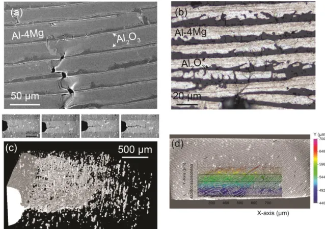
SEM and optical microscopy confirm the cracking of ceramic layers (Fig.5a-b). Crack deflection and wide damage distribution were observed after several loading-unloading cycles. In the X-ray tomography reconstructions was possible to observe that the crack length, measured from error map or directly from the grey level values, varied along the
width of the sample. It was larger at the centre as there may be variations between the sides in plane stress and the centre in plane strain (Fig.5c). These differences can cause errors in the measurement of crack length. A more precise localization of the crack can be done using the errors maps from DVC calculations. Figure 5d shows an error map superposed on the cross section of the material. It appears that the ceramic layers (in white) crack first while metal layers are intact in the wake of the crack.
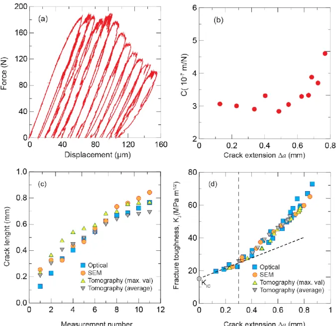
Figs 6a and b show the load-deflection curves and the calculated compliances for a particle-based material. The compliance cannot be used to have an estimation of crack length in these materials as it is often proposed in ceramic-based structures, because it does not vary
significantly due to the large irreversible displacement after unloading. R-curves were calculated using the direct evaluation of the crack length using different techniques. Even if the measurements are slightly different due to the different resolutions of the techniques, no significant variations were observed in the final R-curves (Fig. 6c and d).
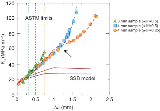
The R-curves of particle-based composites were calculated from crack propagation tests carried out on samples with different thicknesses and notch depths to take into account size effects (Fig. 7). In samples with lower initial a/W ratio the crack propagates longer under small scale bridging (SSB) conditions where the values are valid. This initial propagation is followed by a very fast rise in the R-curve due to large scale bridging (LSB) that invalidates the measurement.
3.4 Comparison of the particle and the platelets based materials
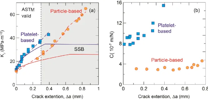
Rising R-curves were obtained for all materials indicating that they became tougher as the crack propagates inside the microstructures due to the activation of several extrinsic and intrinsic toughening mechanisms. The R-curve for the platelet-based composites rises faster with crack propagation (Fig. 8). The R-curve for the particle-based composites does not reach a steady-state plateau but after an initial linear part increases exponentially (Fig. 8). Different trends were also observed in the compliance vs crack length for the two different types of composites (Fig. 8b). The compliance of the particle-based composites changes minimally with crack propagation while the compliance of the platelets-based one varies significantly as the crack grows, suggesting that different fracture mechanisms are activated within the two microstructures.
No de-bonding was observed at the metal-ceramic interfaces after fracture implying a strong adhesion (Fig. 9). The metal layers undergo extensive plastic deformation that contributes
significantly to the toughening. The analysis also revealed good metal penetration through the microscopic interfacial roughness between the ceramic and the metal layers. Stable crack growth allowed the observation of the main toughening mechanisms acting within the microstructure using SEM and X-ray tomography. There are differences between the platelet and the particle-based composites. While in the latter the main mechanisms were metal bridging behind the crack wake, plastic deformation of the metal bridges behind and in front of the crack tip, and micro-cracking in front and on the side of the crack (Fig. 10), in the platelet-based composites it was more difficult to identify a clear crack path instead a large damaged area was observed with many cracks starting radially from the notch root (Fig. 10). These cracks together with the vast plastic deformation of the metal phase blunt the crack. The plastic deformation of the metal layers can be appreciated in the TEM analysis (Fig. 11), which shows the microstructure of a single grain in the two specimens. In the Al region far from the crack path, the grain contains some amount of dislocations as a result of thermal stresses due to the fabrication process. In the region close to the crack path, much more deformation can be seen in the format of increased dislocation density and sub-cells with the dislocations concentrating at the cell walls
.
Differences in the crack propagation features for the two types of composites can be also analysed using the DVC calculation on the X-ray tomography (Figs. 11-13). To compare the behaviour of the platelet and the particle-based materials, three types of analysis are carried out. In Figs. 11a and 12a, plane views of the crack surface extracted from the DVC error maps after several loading and unloading cycles are presented. These pictures can be used to correlate the crack location and the morphology of the ceramic layers. The crack surface is coloured with the coordinates of the voxels in the crack growth direction. These images can be used to estimate the crack advance afterdifferent loading steps and to observe the morphology of the crack front. Crack morphology is also reported in Fig. 13 where a 3D view of the crack surface is coloured according to the distance to the mean crack plane. Clearly the platelet-based material (Fig. 13b) exhibits an almost planar crack surface whereas the deviations of the crack in the particle-based material show oscillations of ±150 µm (Fig.13a). From the displacement field measured in the
direction normal to the crack surface an attempt is made to estimate residual crack opening displacement (COD) maps. The DVC error is averaged within the elements of the mesh used for the DVC analysis. This averaged element-wise error map is thresholded to keep only the elements cut by the crack. Then, the difference of the displacement normal to the crack, from one side of the crack to the other is computed and plotted element-wise on Figure 11b and
12b. The COD is thus estimated over the crack surface and can be used to compare the behaviour of the two materials. This COD is not strictly speaking a measure of a
displacement discontinuity. It results from the deformation of the metallic phase that cannot be accommodated by the ceramic. Therefore, it is more a measure of the displacement resulting from the localized plastic deformation accumulated in the metal in the region where the ceramic fails.
The DVC error maps show that crack propagation does not have a constant speed. This has been especially noted for particle-based samples (see difference between the first two images in Fig 11a that represent the samples after two consecutive loading cycles). For the platelet-based material, the increase of the crack length in the ceramic phase was steadier during the test. Calculation of the average crack opening displacement in finite elements gives values up to 8 µm, larger in the particle based material as compared to the platelet based one (when the values of COD are up to 4 µm).
4. Discussion
The microstructures of the ceramic preforms are consistent with previous reports that show that faster cooling rates result in thinner lamellae and pore size [38]. The ceramic walls exhibit a characteristic microscopic roughness determined to some extent by the sucrose used in the suspension [22]. During infiltration the metal reacts with the atmosphere and the ceramic to form small amounts of AlN and spinel. The extent of the reactions, as reported by S.Rao et al. [12], depends on the amount of Mg in the alloy, the temperature, and the dwell time.
All the composites displayed a better strength-toughness compromise than commercial bulk alumina or the Al-4Mg alloy [37]. The refinement of the microstructure (lamellae thickness and pore size) slightly improved both the strength and the fracture toughness. In terms of strength this correlation can be related to a lower probability of finding a large flaw within the lamellae. Moreover composites with higher metal content (ceramic loading of ~9 vol.%, i.e. 20 vol.% of ceramic in the material) showed higher bending strength. Comparing the flexural strength of our composites with other Al2O3/Al composites made from different aluminium alloys, it is possible to notice that higher strength is achieved when high aspect ratio reinforcements such as fibres or platelets were employed, as proven also by this study (Fig.14) [39]–[41]. Due to their lamellar structure, these material reach higher strengths that others with similar or higher ceramic contents [42]–[44]. It is interesting to observe that composites obtained with an analogous pressureless process (Lanxide) exhibit lower flexural
strength than our composites even at higher ceramic content. It might possible that residual porosity affected their mechanical performance [45].
The composites showed values of KIc higher than pure alumina but lower than the aluminium
alloy (KIc ~ 43 MPa·m1/2) [37]. The initiation toughness is consistent with values reported for
other metal ceramic composites and with the expected trend of higher toughness for higher metal contents (Fig. 14). The values of KIc are in the same range than those quoted for other
laminated composites [16], [43], [44], [46], [47]. Values measured in 3-point bending tend to be higher, possibly due to the deviations in the alignment of the notch. As reported by Bloyer et al. [6] there is always some uncertainty on the evaluation of KIc depending upon whether
the pre-crack is located in the metal or in the ceramic layer. It has been demonstrated that the stress field at the crack tip has to reach a critical value to allow the crack to re-nucleate in the following ceramic layer [26]. The increase of the metal thickness imposes a larger far-field stress necessary to propagate the fracture in the brittle phase. However in this case both the metal and the ceramic layers thicknesses were reduced as the freezing speed increased and because the metal volume increase was minimal, the refining of the whole structure seems to be responsible for the higher fracture toughness
The control on the structure at several length scales achieved by freeze casting activates several toughening mechanisms. The result is a growing resistance curve in which the toughness increases with crack extension (Figs. 7 and 8). Similar behaviour has been observed in other laminated ceramic-metal and ceramic-ceramic composites [4], [7], [50]– [53]. In this case, the evaluation of crack initiation parameters KIc is not sufficient to
represent entirely the actual fracture resistance of these materials and it is necessary to evaluate the dependence of toughness with crack extension. One of the critical issues here is how to best measure crack length, as it is not easily defined (not a single crack plane as shown in Fig. 5). Observation in a single plane using electron or optical microscopy could induce errors, as the length of the crack may not be the same along the propagation front. In this case X-ray tomography offers clear advantages. Other sources of errors may be
branching or micro-cracking. However, our comparison of microscopy and tomography suggests that in our materials differences due to the method are minimal and the resulting R-curves are very similar (Fig. 6d).
The compliance analysis (Fig. 8b) revealed the impossibility of using the compliance method to indirectly quantify the crack length on composites with a high volume fraction of metal.
This approach does not describe perfectly the mechanical response and the real fracture toughness vs crack length behaviour for our ceramic-metal laminates. The compliance does not increase significantly as the crack propagates. This trend reveals the simultaneous effect of several toughening mechanisms having a different impact over the compliance of the materials, such as bridging and plastic deformation. Bridging is clearly active within the microstructure (Fig. 10), however is not sufficient to fully describe the mechanical response of the materials. This consideration is also strengthened by the fact that the applied bridging model under-estimates the real fracture resistance as it does not take into consideration the simultaneous activation of the other mechanisms such as the large plastic deformation in the metal layers. Therefore a direct estimation of the crack length should be preferred for such materials.
The propensity of the R-curve for laminate materials to reach a steady state is mainly attributed to which bridging conditions dominate, small-scale (SSB) or large scale bridging (LSB). Small-scale bridging (SSB) prevails when the bridging length is much smaller than both the crack length and the in-plain sample dimensions. Contrarily when the bridging length is large the results become dependent from the crack length and the sample geometry. Differently from previous studies on freeze casted hybrid composites [11][12] where a plateau in the R-curves is often reached, in this study the composites obtained with spherical alumina particles showed a rising R-curve behaviour characteristic of large scale bridging that has been observed previously in many laminate materials when testing laboratory samples [3][37][28][6][38][27][29]. In general with thin metal layers (<1 µm) the R-curve reaches a steady-state; instead thicker metallic layers typically generate a continuously rising curve caused by large scale bridging (LSB) [50]. Previous studies revealed that metal
thickness and metal yield strength influence the shape of the R-curve [26] and the alloy used here (Al-4Mg) exhibit higher plasticity that the soft phases of other freeze casted composites (Al-Si or PMMA) [16], [17].
The R-curve is to be considered valid only when the SSB conditions are satisfied. According to the more conservative ASTM standards (E1820) this validity is limited up to a maximum crack extension given by Δamax = 0.25b (where b is the un-cracked ligament width). This
means that when using 3 mm thick samples with a/W = 0.5 the ASTM valid value for the particle-based composites is 25 MPam1/2 and it raises up to 45 MPam1/2 for the 4 mm sample with a/W=0.25. Four millimetres thick samples with different a/W values, reach
common toughness up to 60 MPam1/2 before the R-curve starts to diverge. We can take this value as an upper toughness estimate that is independent of sample/notch size. Platelet-based composites with a thickness of 3 mm reach toughness of 38 MPam1/2 within the ASTM limits.
In order to model the effect of bridging in the rising R-curve, the bridging contribution, Kb,
can be added to the intrinsic toughness KIc. The total toughness Kf can be estimated as:
𝐾𝑓 = 𝐾𝐼𝑐+ 𝐾𝑏 (3)
To estimate Kb is necessary to know the traction function σ(x) that simplistically can be
considered constant over the total bridging zone and equal to the constrained flow stress σc of
the metal layers. The total contribution of the reinforcement is obtained multiplying the traction function with the volume fraction f of the reinforcement. Therefore equation (1) can be re-written as [7]:
𝐾𝑓 = 𝐾𝐼𝑐 + 𝑓𝜎𝑐 ∙ ∫ ℎ(𝑎, 𝑥)𝑑𝑥0𝐿 (4)
Fitting of the experimental data to equation (4) allows us to obtain values for the constrained flow stress (c) and the length of the bridging zone (a). The values for each condition were obtained iterating the solutions of equation (4) and choosing those that minimized the residuals (the difference between the experimental and the predicted values).
Calculated bridging zones are large (0.5-1 mm) and they seem to be larger for the particle-based systems. The fitting seems to favour longer bridging zones for larger samples what may reflect the fact that the model does not take into account other possible contributions to toughness. The calculated flow stresses are reported in Table 4. They are clearly higher than the flow stress of the metal in unconstrained conditions (estimated to about 300 MPa [37]). However, they can be considered consistent being the metal constrained between micrometre size ceramic pores with rough metal-ceramic interfaces that may enhance mechanical
adhesion.
Comparing the particle-based and the platelet-based materials, a large difference in the calculated constrained flow stress is noted. Limitations in the application of the model certainly exists, such as the fact that the ceramic and metal layers do not have a constant
orientation in the samples and are not perpendicular to the crack plane. Most of the work on metal-ceramic laminates analyse samples were all the layers are aligned in a direction perpendicular to the crack propagation and parallel to the crack front. Here the layers are organized in domains that are rotated with respect to each other and therefore not all them are parallel to the crack front. This can have a substantial effect on the mechanical response. However, the large difference in the metal constrained flow stress for the two materials could be explained by microstructural features and especially by the interface between ceramic and metal layers. As shown in Figs. 1 and 2, the two phases appears as more imbricated in the platelet-based material, with some metal infiltration inside the alumina platelets. Thin ceramic bridges can also be noted between ceramic layers as shown in Fig 1b and illustrated in Fig 2. These features certainly account for a better stress transfer between layers as
supported by the higher ultimate tensile strength of the platelet-based material as compared to the particle-based ones even for a higher metal fraction.
By assuming that the specimen width is much larger than the bridging zone, equation (4) can be used to estimate the maximum fracture toughness under small scale bridging conditions. In this case the R-curve reaches a plateau as toughening saturates. However the maximum predicted values obtained with this approach are even lower than those measured within the ASTM limits. These results suggest that bridging alone is not sufficient to describe fully the fracture resistance of these materials and other mechanisms should also be active.
Crack observation allowed the identification of some of the extrinsic mechanisms. The most active was ductile-ligament bridging, the presence of unbroken metal bridges behind the crack tip that deform plastically, generating closure traction to the crack advance. The residual crack opening displacement calculated with DVC on the tomographic volumes (see Fig. 11b and 12b) confirms the presence of residual stresses in the metal layers in the wake of the crack front. As mentioned in the previous section, the calculated COD results from the deformation of the metallic phase that cannot be accommodated by the ceramic. The COD value is calculated in a finite element of 24 µm side, larger than the metal layers thickness. Therefore a quantification of the residual deformation in the metallic layers is not directly possible. The difference of the maximum COD values between particle and platelet-based composites could be explained by more efficient stress transfer at the metal-ceramic
interface. It was noted that the COD is smaller in the platelet-based materials as compared to the particle one by a factor of two for a similar sample’s deflection. With a mechanically
more efficient interface, the metal will tend to have a higher constrain and less plastic deformation.
Failure in the composites involves the transmission of the crack from a brittle layer to
another, across the ductile metal that imposes a shielding effect on the crack. Extra stress has to be applied to overcome the resistance imposed by the metal layers. When the crack arrests at the interface, before re-nucleating in the next ceramic layer, the metal layers exhibited extensive shear band formation before failure by ductile rupture (Fig.10). This intense shear banding often resulted in the re-nucleation of the crack at a shifted location on the next ceramic layer when compared to the previous one. The shielding effect is therefore enhanced because such offset cracking. When the metal layer shears off at different angle, it increases the work of rupture of the ductile bridge.
Multiple cracking was observed in the brittle ceramic layers for all the composites. Multiple cracking is an additional toughening mechanism as it promotes greater distribution of damage and energy absorption [22]. The transition from single to multiple fracture, depends on
several factors such as the flow properties of the metal, the scale of the microstructural features and the properties of the metal/ceramic interface [22], [52]. In layered composites, the parameter that mostly controls the occurrence of multiple cracking is the metal layer thickness tm to the ceramic layer thickness tc ratio. Multiple cracking always occur above a
critical ratio of tm/tc. This critical value, in turn, is related to the ratio between the metal
constrained yield stress σm and the ceramic fracture stress σc and tends to increase as σm/σc
decrease. However the models predict that, independent of the physical properties of the metal and the ceramic, multiple cracking prevails if the thickness of the metal is 2.5 times larger than the ceramic layer [16], [22]. In our composites, tm/tc is always >2.5 (tm/tc≈5.5 and
3.5 for 30wt% and 50wt% particles-based composites respectively) implying multiple cracking as observed.
Preforms obtained from spherical alumina particles with 20 and 9 vol.% showed similar fracture toughness values and crack growth propagation. In both types of structures, crack deflection can be also observed in different points (Fig.10a-d and sequence in Fig.5). It is possible that multiple cracking within a single lamella decreases its resistance giving the crack a preferential way to propagate and deflect from the original plane (Fig.10d). It is well known that crack deflection is another effective toughening mechanism that requires
metal penetration through the microscopic interfacial roughness between the ceramic and the metal layers that could increase the interlocking along the interface and contribute to the toughening of the structure.
The fracture process in the platelet-based composites seems slightly different. At low stress intensity values shear bands seemed to be generated around the crack notch (Fig. 10f). Shear sliding that promotes significant crack-tip blunting was recorded at higher fracture toughness values. A vast area of damage forms around the notch root and many cracks and micro-cracks were formed. In addition, extensive plastic stretching was observed in the metal layers
contributing significantly to the toughening of the composite. The reason why the R-curve of the platelet-based composites has a different shape than the one of the particle-based could be related to these differences in the fracture mechanisms. In particular, for these composites, each single lamella is in fact a nacre-like disposition of platelets interlayered by thin metal layers and possibly the fracture process is mainly influenced by the plastic deformation of the metal phase and multiple cracking. Platelet fracture was observed in some cases although a previous study have reported their large strength (~5.3 GPa in bending) [54]. Concerning the fracture of the ceramic phase, prior the metal stretching, a different behaviour was also observed for the two composites as shown with the DVC calculation (see Fig. 11 and 12). The crack propagates with a rather constant speed for the platelet-based composites whereas crack jumps were recorded for the particles-based one. The crack propagates in the ceramic phase by breaking domains with similar orientation [55], which are larger in the particles-based composites and therefore the crack propagates more discontinuously than in the platelets one. This difference in behaviour is also illustrated in Fig. 13 where the crack is shown as being plane in platelet-based material and the rougher in the particle-based material.
5. Conclusions
Pressureless infiltration of liquid Al-4Mg in freeze casted alumina preforms can be used to fabricate ceramic/metal micro-laminated composites with excellent combination of strength and fracture resistance. All the materials exhibited rising R-curve behaviour. The use of different observation techniques (X-ray tomography, SEM or optical microscopy) to measure crack lengths do not affect the R-curve calculations. However, indirect measurement of crack length using compliance can result in significant errors due to large plastic deformation. The structure of the materials plays a role on the mechanical properties. Preforms made from ceramic platelets can be used to fabricate stronger materials (even for metal contents up to 80
vol.%). They can exhibit strengths up to 735 MPa and maximum crack resistance of ~40 MPa·m1/2. Composites obtained from spherical alumina particles reached crack resistance of ~60 MPa·m1/2 under small scale bridging conditions but their strengths were lower (up to 575 MPa). The differences in behaviour can be related to the different toughening mechanisms. While in the platelet-based materials, plastic deformation in the metal and crack branching are highly effective, in the particle-based ones bridging is an important source of toughness. However, the toughening measured cannot be explained using bridging alone, suggesting that other mechanisms such as multiple cracking (that can also be observed) and plastic
deformation are also active.
6. Acknowledgments
The authors would like to acknowledge the European Commission funding under the 7th Framework Program (Marie Curie Initial Training Networks; grant number: 289958, Bioceramics for Bone Repair). We would also like to thank Eric Maire and Jérôme Adrien (MATEIS) for their support with the X-ray tomography.
7. References
[1] R. O. Ritchie, “The conflicts between strength and toughness,” Nat. Mater., vol. 10, no. 11, pp. 817–822, Oct. 2011.
[2] A. G. Evans, “Perspective on the Development of High-Toughness Ceramics,” J. Am. Ceram. Soc., vol. 73, no. 2, pp. 187–206, Feb. 1990.
[3] A. Mortensen and J. Llorca, “Metal Matrix Composites,” Annu. Rev. Mater. Res., vol. 40, no. 1, pp. 243–270, Jun. 2010.
[4] K. L. Hwu and B. Derby, “Fracture of metal/ceramic laminates—II. Crack growth resistance and toughness,” Acta Mater., vol. 47, no. 2, pp. 545–563, Jan. 1999. [5] D. R. Lesuer, C. K. Syn, O. D. Sherby, J. Wadsworth, J. J. Lewandowski, and W. H.
Hunt, “Mechanical behaviour of laminated metal composites,” Int. Mater. Rev., vol. 41, no. 5, pp. 169–197, Jan. 1996.
[6] Z. Chen and J. J. Mecholsky, “Toughening by Metallic Lamina in Nickel/Alumina Composites,” J. Am. Ceram. Soc., vol. 76, no. 5, pp. 1258–1264, May 1993.
[7] D. R. Bloyer, R. O. Ritchie, and K. T. Venkateswara Rao, “Fracture toughness and R-Curve behavior of laminated brittle-matrix composites,” Metall. Mater. Trans. A, vol. 29, no. 10, pp. 2483–2496, Oct. 1998.
[8] J. S. Moya, S. Lopez-Esteban, and C. Pecharromán, “The challenge of ceramic/metal microcomposites and nanocomposites,” Prog. Mater. Sci., vol. 52, no. 7, pp. 1017– 1090, 2007.
[9] A. Mortensen and J. A. Cornie, “On the infiltration of metal matrix composites,” Metall. Trans. A, vol. 18, no. 6, pp. 1160–1163, 1991.
[10] T. W. Clyne and J. F. Mason, “The squeeze infiltration process for fabrication of metal-matrix composites,” Metall. Trans. A, vol. 18, no. 8, pp. 1519–1530, 1987. [11] A. W. Urquhart, “Novel reinforced ceramics and metals: a review of Lanxide’s
composite technologies,” Mater. Sci. Eng. A, vol. 144, no. 1–2, pp. 75–82, Oct. 1991. [12] B. S. Rao and V. Jayaram, “New technique for pressureless infiltration of Al alloys
into Al2O3 preforms,” J. Mater. Res., vol. 16, no. 10, pp. 2906–2913, Oct. 2001. [13] M. K. Aghajanian, M. A. Rocazella, J. T. Burke, and S. D. Keck, “The fabrication of
metal matrix composites by a pressureless infiltration technique,” J. Mater. Sci., vol. 26, no. 2, pp. 447–454, 1991.
[14] P. F. Becher, “Microstructural Design of Toughened Ceramics,” J. Am. Ceram. Soc., vol. 74, no. 2, pp. 255–269, Feb. 1991.
[15] H. D. Espinosa, J. E. Rim, F. Barthelat, and M. J. Buehler, “Merger of structure and material in nacre and bone – Perspectives on de novo biomimetic materials,” Prog. Mater. Sci., vol. 54, no. 8, pp. 1059–1100, Nov. 2009.
[16] M. E. Launey, E. Munch, D. H. Alsem, E. Saiz, A. P. Tomsia, and R. O. Ritchie, “A novel biomimetic approach to the design of high-performance ceramic-metal
composites,” J. R. Soc. Interface, vol. 7, no. 46, pp. 741–753, May 2010.
[17] M. E. Launey, E. Munch, D. H. Alsem, H. B. Barth, E. Saiz, A. P. Tomsia, and R. O. Ritchie, “Designing highly toughened hybrid composites through nature-inspired hierarchical complexity,” Acta Mater., vol. 57, no. 10, pp. 2919–2932, Jun. 2009. [18] V. Naglieri, H. A. Bale, B. Gludovatz, A. P. Tomsia, and R. O. Ritchie, “On the
development of ice-templated silicon carbide scaffolds for nature-inspired structural materials,” Acta Mater., vol. 61, no. 18, pp. 6948–6957, Oct. 2013.
[19] F. Bouville, E. Maire, S. Meille, B. Van de Moortèle, A. J. Stevenson, and S. Deville, “Strong, tough and stiff bioinspired ceramics from brittle constituents,” Nat. Mater., vol. 13, no. 5, pp. 508–514, Mar. 2014.
[20] S. Deville, “Freezing as a Path to Build Complex Composites,” Science (80-. )., vol. 311, no. 5760, pp. 515–518, Jan. 2006.
[21] H. Le Ferrand, F. Bouville, T. P. Niebel, and A. R. Studart, “Magnetically assisted slip casting of bioinspired heterogeneous composites,” Nat. Mater., vol. 14, no. 11, pp. 1172–1179, Sep. 2015.
[22] K. L. Hwu and B. Derby, “Fracture of metal/ceramic laminates—I. Transition from single to multiple cracking,” Acta Mater., vol. 47, no. 2, pp. 529–543, Jan. 1999. [23] Q. Liu, F. Ye, Y. Gao, S. Liu, H. Yang, and Z. Zhou, “Fabrication of a new
SiC/2024Al co-continuous composite with lamellar microstructure and high mechanical properties,” J. Alloys Compd., vol. 585, pp. 146–153, 2014.
[24] S. Roy, B. Butz, and A. Wanner, “Damage evolution and domain-level anisotropy in metal/ceramic composites exhibiting lamellar microstructures,” Acta Mater., vol. 58, no. 7, pp. 2300–2312, 2010.
[25] S. Roy and A. Wanner, “Metal/ceramic composites from freeze-cast ceramic preforms: Domain structure and elastic properties,” 2008.
[26] A. Shaga, P. Shen, C. Sun, and Q. Jiang, “Lamellar-interpenetrated Al-Si-Mg/SiC composites fabricated by freeze casting and pressureless infiltration,” Mater. Sci. Eng. A, vol. 630, pp. 78–84, 2015.
[27] P. M. Hunger, A. E. Donius, and U. G. K. Wegst, “Platelets self-assemble into porous nacre during freeze casting,” J. Mech. Behav. Biomed. Mater., vol. 19, pp. 87–93, Mar. 2013.
[28] S. Deville, E. Saiz, and A. P. Tomsia, “Ice-templated porous alumina structures,” Acta Mater., vol. 55, no. 6, pp. 1965–1974, Apr. 2007.
[29] C. Tallón, R. Moreno, and I. M. Nieto, “Shaping of porous alumina bodies by freeze casting,” Adv. Appl. Ceram., vol. 108, no. 5, pp. 307–313, Jul. 2009.
[30] E. Munch, E. Saiz, A. P. Tomsia, and S. Deville, “Architectural Control of Freeze-Cast Ceramics Through Additives and Templating,” J. Am. Ceram. Soc., vol. 92, no. 7, pp. 1534–1539, Jul. 2009.
[31] F. Bouville, E. Maire, and S. Deville, “Self-Assembly of Faceted Particles Triggered by a Moving Ice Front,” Langmuir, vol. 30, pp. 8656–8663, 2014.
[32] D. Munz and T. Fett, Ceramics, vol. 171. Springer-Verlag Berlin Heidelberg GmbH, 2001.
[33] P. Viot and D. Bernard, “Three-dimensional image correlation from X-ray computed tomography of solid foam,” vol. 39, pp. 1253–1265, 2008.
[34] J. Lachambre, J. Réthoré, A. Weck, and J. Buffiere, “Extraction of stress intensity factors for 3D small fatigue cracks using digital volume correlation and X-ray tomography,” vol. 71, pp. 3–10, 2015.
[35] R. Julien, “Extended digital image correlation with crack shape optimization,” no. May 2007, pp. 248–272, 2008.
[36] P.Leplay, J.Rethore, S.Meille, M.-C.Baietto, J.Adrien, J.Chevalier, and E.Maire, “Three-dimensional Analysis of an In Situ Double-torsion Test by X-ray Computed Tomography and Digital Volume Correlation,” Exp. Mech., vol. 53, pp. 1265–1275, 2013.
[37] R. L. Tobler and R. P. Reed, “Fracture Mechanics Parameters for a 5083-0 Aluminum Alloy at Low Temperatures,” J. Eng. Mater. Technol., vol. 99, no. 4, p. 306, 1977. [38] C. Walter, S. Barg, N. Ni, R. C. Maher, E. Garcίa-Tuñón, M. M. Zaiviji Ismail, F.
Babot, and E. Saiz, “A novel approach for the fabrication of carbon nanofibre/ceramic porous structures,” J. Eur. Ceram. Soc., vol. 33, no. 13–14, pp. 2365–2374, Nov. 2013. [39] S. Wu, A. J. Gesing, N. A. Travitzky, and N. Claussen, “Fabrication and properties of
Al-infiltrated RBAO-based composites,” J. Eur. Ceram. Soc., vol. 7, no. 5, pp. 277– 281, Jan. 1991.
[40] V. Good, K. Widding, G. Hunter, and D. Heuer, “Oxidized zirconium: a potentially longer lasting hip implant,” Mater. Des., vol. 26, no. 7, pp. 618–622, Jan. 2005. [41] S.Long, O.Beffort, G.Moret, and Ph.Thevoz, “Processing of Al-based MMCs by
Indirect Squeeze Infiltration of Ceramic Preforms on a Shot-Control High Pressure Die Casting Machine,” Aluminium, vol. 76, no. 1–2, pp. 82–89, 2000.
[42] H. Prielipp, M. Knechtel, N. Claussen, S. K. Streiffer, H. Müllejans, M. Rühle, and J. Rödel, “Strength and fracture toughness of aluminum/alumina composites with interpenetrating networks,” Mater. Sci. Eng. A, vol. 197, no. 1, pp. 19–30, Jun. 1995. [43] B. A. Huchler, “Pressure Infiltration Behaviour and Properties of Aluminium Alloy -
Oxide Ceramic Preform Composites,” The University of Birmingham, 2009. [44] L.A.Dobrzañski, M.Kremez, A.J.Nowak, and A.Nagel, “Aluminium matrix
composites fabricated by infiltration method,” Arch. Mater. Sci. Eng., vol. 36, no. 1, pp. 5–11, 2009.
[45] M. K. Aghajanian, N. H. MacMillan, C. R. Kennedy, S. J. Luszcz, and R. Roy,
“Properties and microstructures of Lanxide Al2O3-Al ceramic composite materials,” J. Mater. Sci., vol. 24, no. 2, pp. 658–670, Feb. 1989.
[46] M. C. Breslin, J. Ringnalda, L. Xu, M. Fuller, J. Seeger, G. S. Daehn, T. Otani, and H. L. Fraser, “Processing, microstructure, and properties of co-continuous alumina-aluminum composites,” Mater. Sci. Eng. A, vol. 195, pp. 113–119, Jun. 1995. [47] Y.-C. Kang and S. L.-I. Chan, “Tensile properties of nanometric Al2O3
particulate-reinforced aluminum matrix composites,” Mater. Chem. Phys., vol. 85, no. 2–3, pp. 438–443, Jun. 2004.
[48] S. V. Kamat, J. P. Hirth, and R. Mehrabian, “Mechanical properties of particulate-reinforced aluminum-matrix composites,” Acta Metall., vol. 37, no. 9, pp. 2395–2402, Sep. 1989.
[49] K. G. Ewsuk, S. J. Glass, R. E. Loehman, A. P. Tomsia, and W. G. Fahrenholtz, “Microstructure and properties of Al2O3-Al(Si) and Al2O3-Al(Si)-Si composites formed byin situ reaction of Al with aluminosilicate ceramics,” Metall. Mater. Trans. A, vol. 27, no. 8, pp. 2122–2129, 1996.
[50] M. Y. He, F. E. Heredia, D. J. Wissuchek, M. C. Shaw, and A. G. Evans, “The mechanics of crack growth in layered materials,” Acta Metall. Mater., vol. 41, no. 4, pp. 1223–1228, Apr. 1993.
[51] G. R. Odette, B. L. Chao, J. W. Sheckherd, and G. E. Lucas, “Ductile phase
toughening mechanisms in a TiAl-TiNb laminate composite,” Acta Metall. Mater., vol. 40, no. 9, pp. 2381–2389, Sep. 1992.
[52] M. C. Shaw, D. B. Marshall, M. S. Dadkhah, and A. G. Evans, “Cracking and damage mechanisms in ceramic/metal multilayers,” Acta Metall. Mater., vol. 41, no. 11, pp. 3311–3322, Nov. 1993.
[53] D. B. Marshall, J. J. Ratto, and F. F. Lange, “Enhanced Fracture Toughness in Layered Microcomposites of Ce-ZrO2 and Al2O3,” J. Am. Ceram. Soc., vol. 74, no. 12, pp. 2979–2987, Dec. 1991.
[54] E. Feilden, T. Giovannini, N. Ni, C. Ferraro, E. Saiz, L. Vandeperre, and F. Giuliani, “Micromechanical strength of individual Al2O3 platelets,” Scr. Mater., vol. 131, pp. 55–58, 2017.
[55] A. Lichtner, D. Roussel, D. Jauffres, C. L. Martin, and R. K. Bordia, “Effect of Macropore Anisotropy on the Mechanical Response of Hierarchically Porous Ceramics,” J. Am. Ceram. Soc., vol. 99, no. 3, pp. 979–987, 2016.
Table 1. Coefficients of polynomial fit for SENB weight function
ν µ=0 1 2 3 4
0 0.4980 2.4463 0.0700 1.3187 -3.067
1 0.5416 -5.0806 24.3447 -32.7208 18.1214
2 -0.19277 2.55863 -12.6415 19.7630 -10.986
Table 2. Microstructural features of freeze casted Al2O3/Al-4Mg composites. The metal layer width of the platelets-based scaffolds is not reported because the platelets are not perfectly aligned within each lamella and thin metal films can be observed between platelets.
Porosity of the preform (%)
Width of ceramic layer (µm)
Width of metal layer (µm)
20 vol.% Particles-5 °C/min 66.0 ± 1.5 8.2 ± 1.4 27.4 ± 3.7 20 vol.% Particles -15 °C /min 66.9 ± 1.4 6.4 ± 0.9 23.8 ± 2.9 9 vol.% Particles -5 °C /min 79.6 ± 0.3 4.1 ± 0.9 23.3 ± 6.0 9 vol.% Particles -15 °C /min 80.7 ± 0.2 3.3 ± 0.6 18.3 ± 4.1 9 vol.% Platelets-5 °C /min 86.6 ± 0.08 ~6.3 ± 1.7 N.A
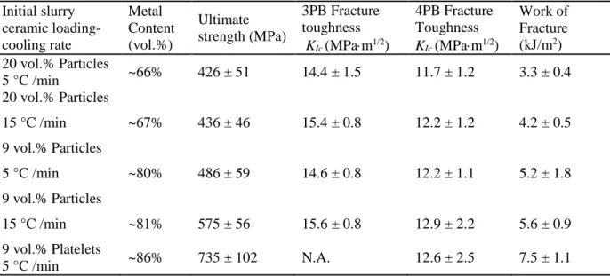
Table 3. Flexural strength, fracture toughness (3 and 4PB) and work of fractures of the composites. Standard deviations are reported.
Initial slurry ceramic loading-cooling rate Metal Content (vol.%) Ultimate strength (MPa) 3PB Fracture toughness KIc (MPam1/2) 4PB Fracture Toughness KIc (MPam1/2) Work of Fracture (kJ/m2) 20 vol.% Particles 5 °C /min ~66% 426 ± 51 14.4 ± 1.5 11.7 ± 1.2 3.3 ± 0.4 20 vol.% Particles 15 °C /min ~67% 436 ± 46 15.4 ± 0.8 12.2 ± 1.2 4.2 ± 0.5 9 vol.% Particles 5 °C /min ~80% 486 ± 59 14.6 ± 0.8 12.2 ± 1.1 5.2 ± 1.8 9 vol.% Particles 15 °C /min ~81% 575 ± 56 15.6 ± 0.8 12.9 ± 2.2 5.6 ± 0.9 9 vol.% Platelets 5 °C /min ~86% 735 ± 102 N.A. 12.6 ± 2.5 7.5 ± 1.1
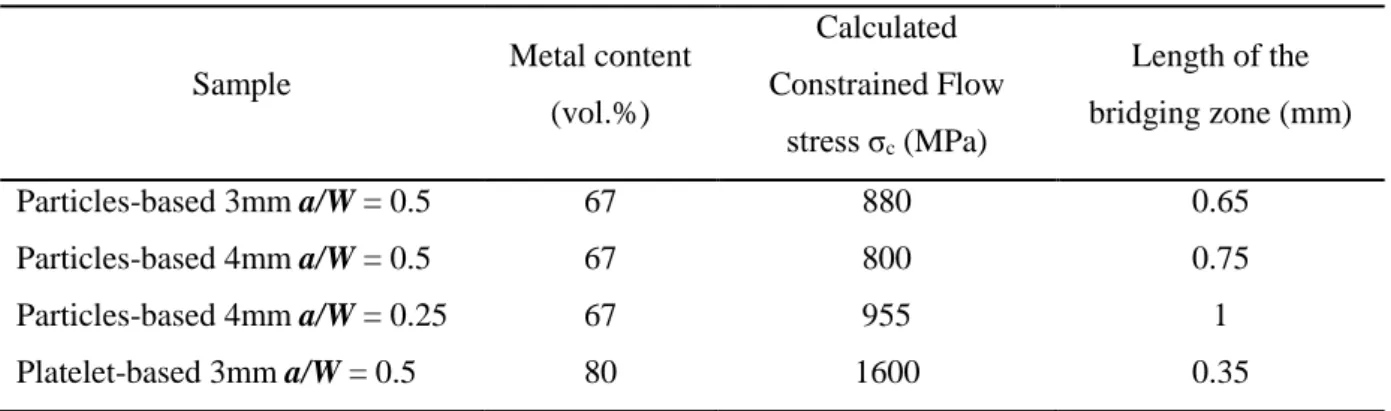
Table 4. Calculated values of constrained flow stresses and size of the bridging zone.
Sample Metal content
(vol.%) Calculated Constrained Flow stress σc (MPa) Length of the bridging zone (mm) Particles-based 3mm a/W = 0.5 67 880 0.65 Particles-based 4mm a/W = 0.5 67 800 0.75 Particles-based 4mm a/W = 0.25 67 955 1 Platelet-based 3mm a/W = 0.5 80 1600 0.35
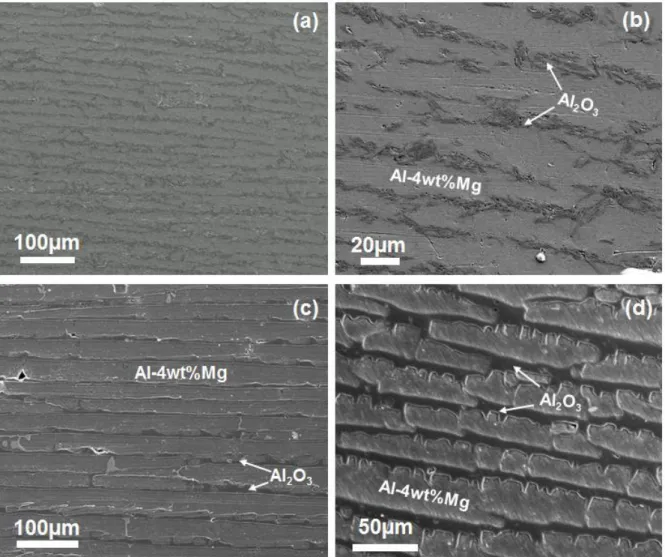
Figure 1. Microstructures of laminated alumina/aluminium composites produced in this study. The microstructure can be manipulated by varying the solid loading of the starting ceramic slurry and the freezing rate. Alumina particles with different morphologies generate different types of lamellar reinforcement. a) and b) 9 vol.% alumina platelets-based composites; c) 9 vol.% particles-based composites. d) 20 vol.% particles-based composites. All samples displayed were frozen at 5 °C/min. In all the pictures the ceramic and the metal appear as the dark and the bright phases respectively.
Figure 2. Alumina platelets arranged within a lamella. The platelets are not perfectly aligned and some porosity remained between them before infiltration. It is also possible to observe that the metal in same parts has infiltrated this porosity between the platelets generating a nacre-like structure within the lamellae.
Figure 3.
X-ray diffraction pattern of a pressureless infiltrated sample. As reported in previous studies, the Al-4Mg alloy partially reacts with the atmosphere and the preform to form small amounts of AlN and spinel (MgAl2O4).[12], [13]
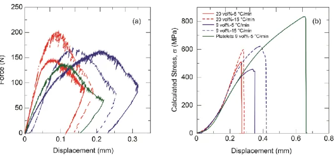
Figure 4. (a) Load-displacement curves for notched SENB specimens (displacement rate 0.01
mm/min) and (b) calculated stress-displacement curves for bending strength specimens (displacement rate 0.05 mm/min).
Figure 5. Crack imaging using different techniques: a) SEM; b) optical microscopy and c) X-ray tomography of crack propagation within a 20 vol.%-5 °C/min particle-based composite. In c) the top sequence of images shows crack progression after several loading-unloading cycles. The crack deflects at different points from the primary plane of propagation. The image at the bottom shows a 3D reconstruction of the damaged area; d) 2D view of the thresholded DVC error superposed to the mid-plane of the X-ray image.
Figure 6. (a) Loading-unloading curve for a particle-based composite (20 vol.%-15 oC/min). (b) Compliance vs crack length for the particle-based composite. (c) Crack size measurements obtained during bending a particle-based composite (20 vol.%-15 oC/min) with different observation
techniques (SEM, optical microscope and X-ray tomography). (d) Corresponding R-curves calculated with crack lengths measured using three different direct observation techniques. For X-ray
tomography the maximum value of crack extension through the whole specimen was considered. A linear fitting can be used to fit the R-curves up to the ASTM crack extension limit for valid
measurements that for this sample is 0.3 mm (vertical doted line). The values obtained beyond this limit are not valid according to the ASTM standards because the measurements are taken under large scale bridging conditions.
Figure 7. R-curves for particle-based samples (20 vol.%-15 oC/min) with three different geometries. Dashed lines are the curves predicted using equation (4). The full lines represent the predicted R-curves for small scale bridging. Vertical lines are the ASTM limits for valid measurements (increasing with increasing sample size and decreasing a/W). The black arrow indicates the point at which the size effects cause a divergence in the measurements for samples with same size but different a/W.
Figure 8. a) R-curves for platelets and particles-based (20 vol.%-15 oC/min) composites. The crack length has been measured by SEM. For the platelet-based composite, the R-curve has a different shape that for the particle-based ones and reaches a maximum KJ of ~40 MPa.m1/2 within the ASTM limit. The dashed and the full lines are the predictions of the analytical model [7] if LSB or SSB prevail respectively. For the LSB model two different bridging lengths have been considered. ASTM limits are also included. b) Crack length vs compliance for the two types of composites considered in this study.
Figure 9. a) Fracture surface of a particle-based (20 vol.%-15 oC/min) composite. b) Detail of the fracture surface showing that the metal infiltrates the microscopic roughness of the ceramic layers (white arrows) suggesting good wetting. The infiltration promotes interlocking between the metal and the ceramic layer.
Figure 10. Crack propagation in the different materials. a-d) crack propagates in the particle-based (9 vol.%-15 oC/min) composites; crack deflection, plastic deformation in the metal layers (pointed by the
white arrows in (c)) and microcraking can be observed;(e-f) crack propagation and fracture
mechanisms acting within platelet-based composites; multiple cracking can be observed at the notch root. The black arrows indicate the crack propagation direction.
Figure 11. Microstructure of the aluminium layer (a) Far from the crack path. Some dislocations are arrowed. (b) next to the crack path. The inset of (b) show the dislocation network at higher
magnification. The analysis has been done on a particles based composites with 20 vol% solid loading, frozen at 15 K/min.
Figure 12. Crack propagation in a particle-based composite (20 vol.% - 15 oC/min). a) 2D view of the DVC error maps for different X-ray scans supperposed to the X-ray image of the material before failure. The color map corresponds to the y coordinate in the image frame in voxel. b) Displacement amplitude in the direction normal to the mean crack plane for the elements cut by the crack as extracted from the DVC error map. The crack grows from the top image to the bottom.
Figure 13. Crack propagation in a platelet-based composite. a) 2D view of the DVC error maps for different X-ray scans superposed to the X-ray image of the material before failure. The colour map corresponds to the y coordinate in the image frame in voxel. b) Displacement amplitude in direction normal to the mean crack plane for the elements cut by the crack as extracted from the DVC error map. The crack grows from the top image to the bottom.
Figure 14. Crack surfaces extracted from the DVC error map coloured by the distance to the mean crack plane in µm. a) particle based composite, b) platelet based composite.
Figure 15. Comparison of strength and toughness (KIC) for different alumina/aluminium composites. The arrows indicated the KJ for the studied materials and for other similar microstructures. KJ for our materials are taken within the ASTM conditions or up to the limit where the measured toughness does not depend on sample/notch size. Some of the references reported the ultimate strength of the
composite under tensile test while others use bending. Data taken from [16], [39], [42], [43], [45], [48], [49]