HAL Id: hal-03106584
https://hal.archives-ouvertes.fr/hal-03106584
Submitted on 11 Jan 2021
HAL is a multi-disciplinary open access
archive for the deposit and dissemination of
sci-entific research documents, whether they are
pub-lished or not. The documents may come from
teaching and research institutions in France or
L’archive ouverte pluridisciplinaire HAL, est
destinée au dépôt et à la diffusion de documents
scientifiques de niveau recherche, publiés ou non,
émanant des établissements d’enseignement et de
recherche français ou étrangers, des laboratoires
Workspace Analysis in the Design Parameter Space of a
2-DOF Spherical Parallel Mechanism for a Prescribed
Workspace: Application to the Otologic Surgery
Damien Chablat, Guillaume Michel, Philippe Bordure, Swaminath
Venkateswaran, Ranjan Jha
To cite this version:
Damien Chablat, Guillaume Michel, Philippe Bordure, Swaminath Venkateswaran, Ranjan Jha.
Workspace Analysis in the Design Parameter Space of a 2-DOF Spherical Parallel Mechanism for
a Prescribed Workspace: Application to the Otologic Surgery. Mechanism and Machine Theory,
Elsevier, 2021, 157, pp.104224. �10.1016/j.mechmachtheory.2020.104224�. �hal-03106584�
Workspace Analysis in the Design Parameter Space of a
2-DOF Spherical Parallel Mechanism for a Prescribed
Workspace: Application to the Otologic Surgery
Damien Chablata,∗, Guillaume Michelb, Philippe Bordureb, SwaminathVenkateswarana, Ranjan Jhac
a
Laboratoire des Sciences du Num´erique de Nantes, UMR CNRS 6004, Nantes, France.
b
CHU de Nantes, 1, place A. Ricordeau, 44093 Nantes, France.
c
BioMedical Instrumentation Division, CSIR- Central Scientific Instruments Organisation, Chandigarh, India.
Abstract
During Otologic surgery, and more broadly during microsurgery, the surgeon en-counters several difficulties due to the confined spaces and micro-manipulations. The purpose of the paper is to design a robot with a prescribed regular workspace shape to handle an endoscope to assist the Otologic surgery. A spherical parallel mechanism with two degrees of freedom is analysed in its design parameter space. This mechanism is composed of three legs (2USP-U) to connect the base to a moving platform connected to a double parallelogram to create a remote center of motion (RCM). Its kinematic properties, i.e. the singularity locus and the number of direct kinematic solutions, are investigated. For some design param-eters, non-singular assembly modes changing trajectories may exist and have to be investigated inside the prescribed regular workspace shape. Two sets of design parameters are presented with their advantages and disadvantages.
Keywords: Spherical Mechanism, Otologic Surgery, Cusp points, Parallel robot, Singularities
Highlights
• Design of mechanism for Otologic Surgery; • Kinematic structure of the proposed mechanism;
• Workspace and Joint space analysis of the proposed 2-DOF Spherical mechanism;
• Influence of the design parameter on the workspace properties;
• Workspace without non-singular assembly modes changing trajectories.
∗Corresponding author
Email addresses: [email protected](Damien Chablat),
[email protected] (Guillaume Michel), [email protected] (Philippe Bordure), [email protected] (Swaminath Venkateswaran), [email protected](Ranjan Jha)
Nomenclature
1
SIROP A Library f or manipulator singularities analysis
CAD Cylindrical Algebraic Decomposition
IKP Inverse Kinematic problem
DKP Direct Kinematic problem
det Determinant of Jacobian matrix
R Revolute Joint
P P rismatic Joint
S Spherical Joint
ρ Actuated Joint V ariables
X P ose V ariables
A Direct parallel Jacobian matrices
B Inverse serial Jacobian matrices
Sα sin(α) Sβ sin(β) Cα cos(α) Cβ cos(β) 1. Introduction 2
Traditionally, the ear surgeries are performed under binocular Loupes, which
3
allows the surgeon to use both hands during the surgery. Presently, the
devel-4
opment of Otologic surgery by endoscopy allows a better view of areas difficult
5
to access [1, 2]. However, the use of an endoscope restricts the surgeon to use
6
both the hands while doing surgery. Therefore, there is a strong expectation
7
on the part of the otologic surgeon for a robotic assist system to perform the
8
surgery comfortably.
9
There are many advantages for using an endoscope instead of the
conven-10
tional microscope in otologic surgery. Some of them include a better view with
11
easy access to the operation area and proximity to the patient during the
op-12
eration. Endoscopic surgeries result in less bone sacrifice and thus improve the
13
patient’s recovery period. Despite the many advantages, endoscopic surgeries
14
pose different challenges for the surgeon. Currently, the surgeon can only use
15
one tool at a time in endoscopic surgery, as opposed to two tools with the use
16
of a microscope, as shown in Figure 1. This makes endoscopic surgeries
cum-17
bersome because the surgeon must switch from one tool to the other to operate
18
and manage bleeding in the ear. At the time of patient set-up, several factors
19
can change the anatomical position of the head and thus the workspace in which
20
the robot must operate. This leads to changes in the robot’s approach angle.
21
It must be able to compensate for this by working amplitudes that are greater
22
than the working space inside the ear alone.
23
This paper is organized as follows. The first part comprises of the application
24
of robot for the otologic surgery in order to determine the required workspace. A
25
two DOF RCM spherical mechanism is proposed in the second part with detailed
26
kinematic equations. The third part reports the singularity and workspace
27
analysis of the proposed robot in the design parameter space with two case
28
studies to fulfil the design requirements. In the later parts, discussions and
29
conclusions are presented.
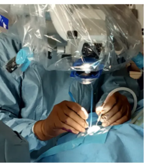
(a) The use of single hand to hold endoscope limits the number of instruments
(b) The surgeon can use two instruments while using a microscope
Figure 1: The comparison of the number of instruments possible to use simultaneously while using an endoscope and a microscope (Dr. Guillaume Michel, CHU Nantes).
2. Application of Robotics for otologic surgery
31
2.1. Robotics for otologic surgery
32
Currently, several robotic systems are developed [3], reflecting the interest for
33
robotic assistance in microscopic surgery. In the context of designing a robot to
34
assist the surgeon in otologic surgery, a spherical robot with a parallel structure
35
associated with a double parallelogram was developed [4]. This robot can handle
36
an endoscope to increase the efficiency of the surgeon when compared to the
37
classical binocular performed surgery. The parallel structure should increase the
38
rigidity compared to the existing solution [5]. Many spherical mechanisms exist
39
[6, 7, 8, 9, 10]. They can be divided into two main families (i) those with a virtual
40
center of rotation and (ii) those constrained by a spherical joint or a universal
41
joint (three or two DOF). To form a remote center of motion (RCM), one
42
solution is to use a universal joint associated with two parallelograms. Actuation
43
can be done with prismatic or revolute actuators. The advantage of prismatic
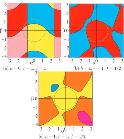
44
actuators is that there is only one solution to the inverse geometric model or
45
one working mode [11, 12]. In order to give the surgeon more mobility, it is
46
necessary to have the largest working space without singularity. By adding an
47
offset in the classical design, we are able to increase this workspace but the
48
properties of the robot change [13]. In [13] the parameter h is added between
49
the universal joint and the mobile platform but the offset on the both legs are
50
removed.
51
For most parallel or serial manipulators, pose variables and joints variables
52
are linked by algebraic equations and form a so called algebraic variety
(some-53
times after a straight forward change of variables). The two-kinematic problems
54
(the direct kinematic problem (DKP) and the inverse kinematic problem (IKP))
55
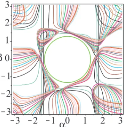
consist in studying the pre-image of the projection of this algebraic variety onto
56
a subset of unknowns. Solving the DKP remains to computing the possible
57
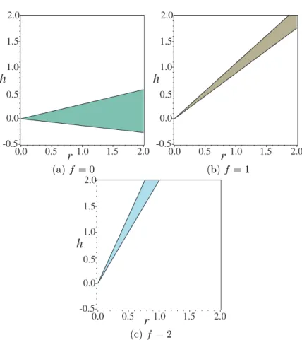
poses for a given set of joint variables values while solving the IKP remains
to computing the possible joints variables values for a given pose. Algebraic
59
methods have been deeply used in several situations for studying parallel and
60
serial mechanisms, but finally their use is quite confidential in the design
pro-61
cess. The number of aspects changes and the number of solutions to the DKP
62
increases. This means that the presence of cusp points or the uniqueness
do-63
mains in the workspace must be investigated [14]. In this paper we will present
64
the mechanism properties for a given offset that allow non-singular assembly
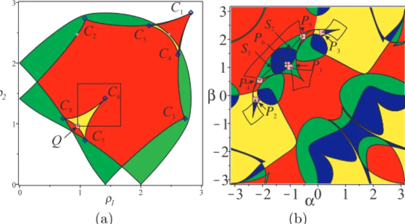
65
mode changing trajectories [15]. The SIROPA library written in Maple will be
66
used to compute the singularity equations using Groebner bases, do the
cylin-67
drical algebraic decomposition (CAD) as well as the trajectories [16, 17]. The
68
paper presents the design of a robotic system, which assist the surgeon in
visu-69
alizing the inner part of the ear while performing surgery using an endoscope.
70
This would facilitate the use of the endoscope in microsurgery or even replace
71
any use of the operating microscope. The study of workspace, joint space and
72
singularities together assists the engineers and researchers in the efficient task
73
planning and the selection of the particular configuration of the manipulator for
74
a desired task.
75
In this paper we will present the mechanism properties for a given offset
76
that allow non-singular assembly mode changing trajectories [15]. The SIROPA
77
library written in Maple will be used to compute the singularity equations using
78
Groebner bases, do the cylindrical algebraic decomposition (CAD) as well as the
79
trajectories [16, 17]. The paper presents the design of a robotic system, which
80
assist the surgeon in visualizing the inner part of the ear while performing
81
surgery using an endoscope. This would facilitate the use of the endoscope in
82
microsurgery or even replace any use of the operating microscope. The study
83
of workspace, joint space and singularities together assists the engineers and
84
researchers in the efficient task planning and the selection of the particular
85
configuration of the manipulator for a desired task.
86
2.2. Specifications for the otological surgeries
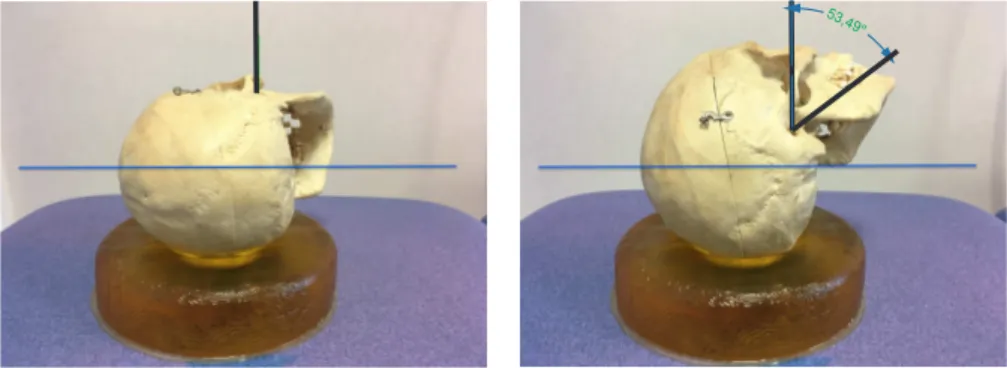
87
Figure 2 shows the ear in two orientations. The optimal position, for most
88
of the otological surgeries, is when the mastoid is horizontal. Unfortunately,
89
the patient’s anatomy does not always allow the ear to be in this position. In
90
the figure on the right, the axis of the ear can therefore be tilted by about
91
54◦. Mobility inside the ear has been studied in [18] with a scan analysis on a
92
population of variable age and sex (n=16, patients from 2 to 79 years old). It
93
can be hypothesized that the center of rotation of the endoscope will be placed
94
in the middle of the ear canal as shown in Figure 3.
95
In this study, we can isolate the dimensional parameters giving maximum
96
angular variation. Figure 4 represents these variations with a zero diameter
97
for the endoscope in the centre and on the right and left for an endoscope of
98
3 and 4 mm diameter where the tilt angles are equal to ±13◦ and ±11◦. To
99
ensure that the robot can be used for all patients as well as having the necessary
100
mobility for all ears. Figure 5(left) depicts the nominal cone and its inclination
101
of 54◦ to reach the most inclined position of Figure 3. The total angle becomes
102
67◦. However we must slightly increase this value because we will define the
103
limit of the workspace by the singularities, where the robot behavior will be less
104
accurate. We choose to search for a tilt angle close to 75◦. Workspace can be
105
defined using azimuth, tilt and torsion representation [19] where azimuth angle
106
is [0...360◦], tilt angle is [0...75◦] and no torsion. For the studied mechanism, we
53,49 °
Figure 2: Placement of the ear in relation to the operating table in the optimal (right) and unfavourable (left) position
Figure 3: Schematic workspace of the external (cylinder) and middle ear
will use a universal joint based on two orthogonal revolute joints α and β. Figure
108
5(right) depicts in red the image of the regular workspace shape [20] requested
109
to have the tilt motion in the Euler coordinates. It is possible to include this
110
space either by a square defined by α = β = [−75◦...75◦] or a centered circle
111
with a radius equal to 75◦.
112
Another constraint is to limit the possible interference between the
mecha-113
nism and the surgeon. Therefore, we can offset the center of rotation by using
114
a RCM made by parallelograms.
115
3. A remote center of motion mechanism to carry an endoscope
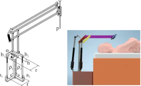
116
Figure 6 shows an RCM mechanism carrying an endoscope for operations in
117
the ears made by coupling two DOF spherical mechanism with double
parallel-118
ograms. This mechanism is coupled to a translation mechanism for positioning
119
in the middle ear centre. Another mechanism, not shown in the figure, allows
120
translation of the endoscope for insertion, cleaning and ejection in case the
34° 27.4 6.5 10.2 22° 26° 3 4
Figure 4: Mobility of the endoscope inside the middle ear
67° 54° 13° -1.5 -1 -0.5 0 0.5 1 1.5 -1.5 -1 -0.5 0 0.5 1 1.5 a b
Figure 5: Prescribed regular workspace shape for Otologic surgery
patient wakes up (patent pending) [21]. The spherical parallel mechanism is
122
composed of three limbs and one moving platform. The two first legs, UPS, are
123
composed of a universal joint, a prismatic joint and a spherical joint and the
124
last one is made by a single universal joint and constrains its mobility. The two
125
prismatic joints are actuated. The double parallelogram is attached to the two
126
axes of this joint. Usually, the end points of the UPS legs are in the same plane
127
as the axes of rotation of the universal joint.
128
In order to obtain the desired workspace, it is possible to vary several design
129
parameters. In this study, one parameter is normalized, the structure remains
130
symmetrical and three length parameters are varied.
a
1o
p
a
2b
1b
2ρ
1ρ
2h
r
f
o
Figure 6: RCM Mechanism with spherical parallel mechanism in its home pose and its location close to the patient
131
3.1. Kinematic equations
132
Let a1and a2be attached to the base, O the center of the universal joint and
The coordinates are given by
o= [0, 0, 0] , a1= [f, 0, −1]T, a2= [0, f, −1]T, b1= [r, 0, h]T, b2= [0, r, h]T
(1) The orientation space of the moving platform is fully represented with the vari-ables (α, β). The rotation matrix R from the base frame to the moving frame is expressed as follows: R= RαRβ= Cβ 0 Sβ SαSβ Cα −SαCβ −CαSβ Sα CαCβ (2)
The orientation angles are defined in such a way that α = β = 0, which repre-sents the “home” pose as depicted in Figure 6. The coordinates of b1 and b2
can be written in the base frame as
c1= Rb1 c2= Rb2 (3)
The distance constraints from the two prismatic joints yields
||aici|| = ρi with i = 1, 2 (4)
This leads to the two constraint equations:
133
−2(f h + Cαr)Sβ+ 2(hCα− f r)Cβ+ f2+ h2+ r2+ 1 = ρ21 (5)
2h(f Sα+ Cα)Cβ− 2f Cαr + f2+ h2+ r2+ 2Sαr + 1 = ρ22 (6)
4. Singularity and workspace analysis
134
The singularity analysis is done by differentiating the two constraint equa-tions with respect to time that leads the velocity model:
Aω + B ˙ρ = 0 (7)
where A and B are the parallel and serial Jacobian matrices, respectively, ω
135
is the angular velocity and ˙ρ = [ ˙ρ1 ˙ρ2]T joint velocities [11]. The singularity
136
locus in the worskspace can be written as follows without specifying the design
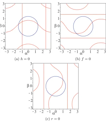
137 parameters f , r and h [22]: 138 4(Cβr + h(f + Sβ))r(Cα)2+ (4f2h2(Cβ)2− 4f (−Sαr + h(f Sβ− 1))rCβ+ 4(h(f Sβ− 1)Sα− f Sβr)r)Cα+ 4f ((−h2Sα+ rh)(Cβ)2+ h(r(f + Sβ)Sα+ Sβh)Cβ− r(f rSβSα+ h)) = 0 (8)
There are three conditions for simplifying and factorizing the singularity
equa-139
tion.
140
•
h = 0: (sin(α) + cos(α))(+ sin(β) − cos(α) cos(β)) = 0141
•
f = 0: cos(α)r(h sin(α) − cos(α) cos(β)r − cos(α) sin(β)h) = 0142
•
r = 0: cos(β)f h2(cos(α) cos(β)f − sin(α) cos(β) + sin(β)) = 0(a) h = 0 (b) f = 0
(c) r = 0
Figure 7: Singularity locus in the workspace of the spherical joint with four aspects where red represents the singularity locus and blue represents the border of the regular workspace shape
When there is simplification of the singularity equations, the DKP admits
144
two of four solutions and each one is located in a given aspect which refers to the
145
maximum singularity free regions in the workspace. These properties are not
146
stable because when a small offset is added, the locus of the singularities changes.
147
The aspects, i.e. the maximum singularity free regions in the workspace are
148
shown in Figure 8 where there are four aspects as shown in Figure 8(a) and (c)
149
and only two in Figure 8(b) [11].
150
When there is less aspect than solutions to DKP, it means that non-singular
151
assembly mode change trajectories exist, in other words that the mechanism is
152
cuspidal. In order to guarantee the safety of the movements, it is necessary to
153
analyze the uniqueness domains and the behavior around the cusp points.
154
4.1. Sets of design parameters for the desired workspace
155
The search for design parameters allowing the inclusion of the desired workspace
156
can be done by optimization or by analyzing the number of intersections
be-157
tween the singularities and the workspace boundary. This is the second solution
158
which is used in this study. It consists in using the CAD of a system formed by
159
the parametric polynomial system of singularities and the equation of the circle,
160
border of the workspace. This system is a function of three design parameters
(a) h = 0, r = 1, f = 1 (b) h = 1, r = 1, f = 1/2
(c) h = 1, r = 1, f = 1/2
Figure 8: Singularity locus and aspects in the workspace for three sets of parameters where each color represents a given aspect
and α and β angles.The CAD decomposes the parameter space of the system
162
into cells in which the original system has a constant number of solutions and
163
we retain the components with zero solutions. For each cell obtained, the CAD
164
returns the values of a set of parameters. The following list is obtained by
vary-165
ing by discretization the parameter f to have a 2D view of the other parameters
166
h and r. Table 1 is a list of solutions by a set of parameters solutions of each cell
167
for r = 1 and Figure 9 depicts the singularity locus of each set of parameters.
168
If the design parameters make it possible to obtain the desired workspace,
169
there are two singularity typologies. Two examples are now presented, one
170
where the equation of factor singularities factorizes and the other where we
171
cannot, to divide the workspace into four aspects. Figure 10(a) is the set of
172
design parameters for f = 0. This set include h = 0 but also small value of h
173
with respect to r. Figure 10(b) and (c) are the set of solutions for f = 1 and
174
f = 2, respectively.
175
4.2. Example 1: h = 0, r = 1 and f = 1/10
176
For h = 0, r = 1 and f = 1/10, the singularity locus is defined as
Figure 9: Singularity locus from the parameters defined in Table 1 where the blue curve is the boundary of the prescribed workspace
h 0 0 0.233 0.408 0.549 0.648 0.735 0.818 0.898 1.038
f 0.1 0.2 0.3 0.4 0.5 0.6 0.7 0.8 0.9 1
h 1 1.204 1.341 1.478 1.616 1.753 2 2 2 2.308
f 1.1 1.2 1.3 1.4 1.5 1.6 1.7 1.8 1.9 2
Table 1: Set of parameters solutions of each cell for r = 1 obtained by the CAD
Figure 11 depicts the workspace and the joint space as well as the boundary
177
of the prescribed workspace. As there is only two (area in green) or four real
178
solutions (area in red) to the DKP and the singularity can be factorized, there is
179
no cusp point in the joint space. As the boundary of the prescribed workspace
180
is on the boundary of the aspect, its image in the joint space is also on the
181
boundary. This solution does not yield a safety problem during the trajectory
182
planning.
183
4.3. Example 2: h = r = f = 1
184
For h = r = f = 1, the singularity locus is defined as
185
2(Cβ+ Sβ+ 1)Cα2+ (2C 2
β+ (−2Sβ+ 2Sα+ 2)Cβ+ (−2Sα+ 2)Cβ2
+ (2Sβ− 2)Sα− 2Sβ)Cα+ ((2Sβ+ 2)Sα+ 2Sβ)Cβ− 2SαSβ = 2 (10)
Figure 12(b) depicts the joint space where the DKP admits either two real
186
solutions, in green, four real solutions, in red and six real solutions, in yellow.
187
Eight cusps exist (i) C1, C2 and C3 are between the two- and four-solution
188
regions solutions to the DKP, and (ii) C4, C5, C6, C7 and C8 are between the
189
four- and six-solution regions. The workspace devided into four aspects (regions
190
in orange, pink, blue and yellow).
191
The analysis of the image of the boundary of the prescribed workspace
(Fig-192
ure 12(a)) in the joint space has been studied in [22]. This curve surrounds 3
193
cusp points C4, C5 and C6(Figure 12(b)). When a prescribed workspace is
in-194
scribed in a single aspect, it does not lead to the conclusion that the trajectories
195
that the robot will make will be in a single domain of uniqueness, i.e. there is
196
no non-singular assembly mode changing.
h
r
2.0 1.5 1.0 0.5 0.0 -0.5 0.0 0.5 1.0 1.5 2.0h
r
2.0 1.5 1.0 0.5 0.0 -0.5 0.0 0.5 1.0 1.5 2.0 (a) f = 0 (b) f = 1h
r
2.0 1.5 1.0 0.5 0.0 -0.5 0.0 0.5 1.0 1.5 2.0 (c) f = 2Figure 10: Set of solutions obtained by CAD
(a) (b)
Figure 11: Workspace (a) and joint space (b) without any cusps points with the boundary of the prescribed workspace and its image in the joint space for h = 0, r = 1 and f = 1/10
Either point Q belonging to the workspace boundary whose image in the
198
workspace is located in a region where DKP admits six solutions, called Pi. We
199
realize a loop that includes the cusp point C6 (Figure 13(a)).
200
The images of this trajectory shown in Figure 13(b) in the workspace are
C 2 C5 C 4 C 1 C 3 C 7 C 6 C 8 (a) (b)
Figure 12: Workspace (a) and joint space (b) with height cusps points with the boundary of the prescribed workspace and its image in the joint space for h = r = f = 1
cated in basic regions depicted in yellow and blue regions where det(A) > 0 and
202
in basic region depicted in red and green where det(A) < 0. In Figure 13(b), we
203
can observe from any stating point Pi (i) two singular trajectories between two
204
aspects (P4− P6and P5− P6) and meet singular positions in S1and S2,
respec-205
tively, (ii) one non-singular changing trajectory in the same aspect (P4− P5),
206
and (iii) three loops in the workspace located in the same aspect (P1− P1,
207
P2− P2, P3− P3). Only the trajectory (P1 − P1) is located in the regular
208
workspace shape. We can therefore conclude that even if this trajectory
sur-209
rounds a cusp point in the joint space, it is not a non-singular trajectory in a
210
changing assembly mode.
211 C2 C 5 C4 C1 C3 C7 C6 C8 Q P 1 P 6 P4 P2 P 5 P3 S 1 S 2 (a) (b)
Figure 13: Trajectory that encircles a cusp point in the joint space and its image in the workspace
4.4. Discussions
212
The study of mechanism in the design parameter space allows a better
un-213
derstanding of the architecture and the working of the 2-PUS-U robot. There
214
are three design parameters (namely f , r and h) associated with the proposed
o
a
1a
2b
1b
2n
o
o
o
n
n
n
n
o
b
1o
n
b
2a
1a
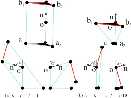
2 α α α α (a) h = r = f = 1 (b) h = 0, r = 1, f = 1/10Figure 14: Graphic rendering of the two cases under study in the home pose and for α = ±75◦
with the mobile platform in red and n the normal to the mobile platform
robot. The singularity equation is analysed, based on the three conditions
216
(f = 0, r = 0 and h = 0), which further helps to simplify and factorize the
217
singularity equations which is shown in Figure 7. It is shown that robot will
218
have non-singular assembly mode changing trajectories i.e. it will be cuspidal
219
if it has less aspect than the solutions to the DKP. The analysis of uniqueness
220
domains and the behavior around the cusp points infers the safe movement of
221
the robot. The selection of design parameters for the desired workspace is
ob-222
tained by analyzing the number of intersections between the singularities and
223
the workspace boundary. The CAD algorithm is used to compute and visualize
224
the two dimensional surface in h − r plane by varying the design parameter f
225
value. More homogeneous sets of parameters exist but make the robot cuspidal
226
with possible dangers when generating trajectories. It has been shown that in
227
reported case, the part of the workspace studied does not lead to non-singular
228
assembly mode changes. However, this does not allow us to infer this result for
229
all design parameters.
230
Figure 14 depicts the graphic rendering of the robot with the same scaling
231
for the two examples studied. In the “home” position, for the first example, the
232
design is more compact than the second example as the width of the first case
233
is twice the width of the second case while its height is half the height of the
234
second case. However, this selection of design parameters is not generic and it is
235
impossible to design the robot as one of the design parameter equal to zero. At
236
the maximum tilt rotations, it is necessary to take into account the interference
237
problems between the UPS leg actuators and the central link formed by the
238
universal joint.
5. Conclusions
240
Based on the analysis of the surgeon’s needs of otologic operations, the
241
definition of a regular workspace shape was defined. This property allow the
242
robot to be adapted to the human anatomy of a large part of the population. A
243
2UPS-U spherical parallel robot was presented and its kinematic equations were
244
formulated. The properties of this robot were studied in the design parameter
245
space. Several simplifications have been proposed which allow a factorization of
246
the singularity locus when one of the parameters is equal to zero. The workspace
247
can be divided into two or four aspects. A CAD is used to characterize the
248
sets of design parameters where there is no intersection between the singularity
249
curves and the regular workspace shape. From this set of possible solutions,
250
two examples are presented, a non cuspidal robot and a cuspidal robot. Their
251
properties were illustrated in the workspace and in the joint space. In both cases,
252
the prescribed workspace is safe because the robot does not change the assembly
253
mode. Further research will be conducted in order to verify the collision between
254
the legs and the joint limits of the passive joints and to use a kinetostatic criteria
255
to select the optimized design parameters of the mechanism for the surgery
256
application.
257
References
258
[1] Cohen, M.S., Basonbul, R.A., Barber, S.R., Kozin, E.D., Rivas, A.C. and
259
Lee, D.J. Development and validation of an endoscopic ear surgery
classi-260
fication system. The Laryngoscope, 128(4), pp.967-970 (2018).
261
[2] Iannella, G., Marcotullio, D., Re, M., Manno, A., Pasquariello, B.,
An-262
geletti, D., Falasca, V. and Magliulo, G.. Endoscopic vs microscopic
ap-263
proach in stapes surgery: advantages in the middle ear structures
visual-264
ization and trainee’s point of view. The journal of international advanced
265
otology, 13(1), p.14 (2017).
266
[3] Dahroug, B., Tamadazte, B., Weber, S., Tavernier, L. and Andreff,
267
N. Review on otological robotic systems: Toward microrobot-assisted
268
cholesteatoma surgery. IEEE reviews in biomedical engineering, 11,
269
pp.125-142 (2018).
270
[4] Schena, B., Robotic manipulator with remote center of motion and
com-271
pact drive, Patent WO 2008/157225 (2007).
272
[5] Rosen, J., Brown J.D., Chang, L., Barreca, M., Sinanan, M., Hannaford,
273
B., The Blue-DRAGON - a system for measuring the kinematics and
dy-274
namics of minimally invasive surgical tools in-vivo, In: Proc. IEEE
Inter-275
national Conference on Robotics and Automation (2002).
276
[6] Gosselin, C., Hamel, J.-F., The agile eye: a high-performance
three-degree-277
of-freedom camera-orienting device. In: Proc. IEEE international
confer-278
ence on robotics and automation, pp. 781–786 (1994).
279
[7] Cheng H.H., Real-time manipulation of a hybrid serial-and-parallel driven
280
redundant industrial manipulator. ASME J. of Dynamic Systems,
Mea-281
surement and Control, 116(4), pp. 687–701 (1994).
[8] Agrawal S.K., Desmier G., Li S., Fabrication and analysis of a novel 3 dof
283
parallel wrist mechanism, ASME J. of Mechanical Design, 117(2), pp. 343–
284
345 (1995).
285
[9] Caron, F., Analyse et d´eveloppement d’un manipulateur parall`ele
286
sph´erique `a deux degr´es de libert´e pour l’orientation d’une cam´era, M.Sc.,
287
Universit´e Laval, Qu´ebec, August (1997).
288
[10] Karouia M. and Herv`e J.M. A three-dof tripod for generating spherical
289
motion, In ARK, pp.395–402, Piran, 25-29 June (2000).
290
[11] Chablat, D., and Wenger P., Working modes and aspects in fully
par-291
allel manipulators; Proceedings, 1998 IEEE International Conference on
292
Robotics and Automation, Vol. 3 (1998).
293
[12] Bonev, I. A., Chablat D., and Wenger P., Working and assembly modes
294
of the Agile Eye, Proceedings 2006 IEEE International Conference on
295
Robotics and Automation (2006).
296
[13] Kumar, S., Nayak, A., Peters, H., Schulz, C., M¨uller, A., Kinematic
analy-297
sis of a novel parallel 2SPRR+ 1U ankle mechanism in humanoid robot,
In-298
ternational Symposium on Advances in Robot Kinematics. Springer, Cham
299
(2018).
300
[14] Chablat D., Wenger P., S´eparation des solutions aux mod`eles g´eom´etriques
301
direct et inverse pour les manipulateurs pleinement parall`eles, Mechanism
302
and Machine Theory, Vol 36/6, pp. 763–783, (2001).
303
[15] Wenger Ph., Chablat D., Definition Sets for the Direct Kinematics of
Par-304
allel Manipulators, 8th International Conference in Advanced Robotics,
305
pp. 859–864 (1997).
306
[16] Jha, R., Chablat, D., Baron, L., Rouillier, F., Moroz, G., Workspace,
307
joint space and singularities of a family of delta-like robot, Mechanism
308
and Machine Theory, 127, pp. 73–95, (2018).
309
[17] Chablat, D., Moroz, G., Rouillier, F., Wenger, P., Using Maple to analyse
310
parallel robots. In Maple Conference 2019, October, (2019).
311
[18] Michel, G., Haribhau Salunkhe, D., Chablat, D. and Bordure, P., A New
312
RCM Mechanism for an Ear and Facial Surgical Application,
Proceed-313
ings Advances in Service and Industrial Robotics, Springer International
314
Publishing, Cham, pp. 408–418, 2020.
315
[19] Bonev, I. A., D. Zlatanov, and C. M. Gosselin. ”Advantages of the modified
316
Euler angles in the design and control of PKMs.” 2002 Parallel Kinematic
317
Machines International Conference (2002).
318
[20] Chablat, D., Wenger, P., Majou, F., and Merlet, J. P.”An interval analysis
319
based study for the design and the comparison of three-degrees-of-freedom
320
parallel kinematic machines”. The International Journal of Robotics
Re-321
search, 23(6), 615-624, 2004.
322
[21] Chablat, D., Michel, G., Bordure, P. (2019), Dispositif d’aide `a la chirurgie,
323
PCT/EP2020/076353, European Patent.
[22] Chablat, D., Michel, G., Bordure, P., Jha, R., & Venkateswaran, S. (2020,
325
September). Joint space and workspace analysis of a 2-DOF Spherical
Par-326
allel Mechanism. In European Conference on Mechanism Science (pp.
181-327
188). Springer, Cham.