HAL Id: hal-00661347
https://hal.archives-ouvertes.fr/hal-00661347
Submitted on 5 Jan 2017
HAL is a multi-disciplinary open access
archive for the deposit and dissemination of
sci-entific research documents, whether they are
pub-lished or not. The documents may come from
teaching and research institutions in France or
abroad, or from public or private research centers.
L’archive ouverte pluridisciplinaire HAL, est
destinée au dépôt et à la diffusion de documents
scientifiques de niveau recherche, publiés ou non,
émanant des établissements d’enseignement et de
recherche français ou étrangers, des laboratoires
publics ou privés.
Benefits and limitations of parametric design
implementation in helicopter gearbox design phase
Emmanuel Mermoz, Jean-Marc Linares, Alain Bernard
To cite this version:
Emmanuel Mermoz, Jean-Marc Linares, Alain Bernard. Benefits and limitations of parametric
de-sign implementation in helicopter gearbox dede-sign phase. CIRP Annals - Manufacturing Technology,
Elsevier, 2011, 60 (1), pp.199 - 202. �10.1016/j.cirp.2011.03.095�. �hal-00661347�
Benefits and limitations of parametric design implementation in helicopter
gearbox design phase
E. Mermoz (3)
a,*
, J.M. Linares (2)
b, A. Bernard (1)
c´
¨
a
EUROCOPTER, Aeroport de Marseille Provence, 13700 Marignane, France
b
ISM UMR6233, Aix Marseille University, Avenue Gaston Berger, 13625 Aix en Provence Cedex 1, France
c
Ecole Centrale de Nantes, IRCCyN UMR CNRS 6597, BP 92101, 1 rue de la Noe, 44321 Nantes Cedex 3, France
1. Introduction
One main constraint for any company is to increase its performances as compared to its competitors. It requires the improvement of the products quality and the reduction of the time to market. These generic constraints are clearly applicable to helicopter market. The lead time to develop a new helicopter is representing a several years engineering effort. Its duration is mainly the conjunction of 2 parameters which are the complexity of the system to be developed and the level of safety to ensure. Gearboxes development is one of the major contributors to the The purpose of this paper is to present a parametric design methodology has been successfully implemented in Eurocopter to gearboxes.
2. Recall of helicopter gearbox design characteristics 2.1. The gearbox product
The role of the main gearbox is to transform the mechanical power generated by the engines (from 0.3 to 4 MW depending on the size of the helicopter). The engine rotational speed (from 6000 RPM to 23,000 RPM) is reduced according the rotor needs to lower values (from 400 RPM to 160 RPM).
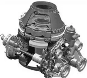
A helicopter gearbox is a complex system based on several combinations of power gear trains with specific power bearings, installed into complex housing (Fig. 1). The configuration of the gear train is the result of geometrical constrain given by the
helicopter architecture together with power gears sizing. The role of the gearboxes on helicopter is not limited to mechanical power transformation and distribution. Indeed, gearboxes also provide a geometrical and mechanical links between many subsystems of the helicopter dynamic system such as engines, servo actuators, tail drive shafts and rotors systems.
2.2. The gearbox design process
During the design process of a new helicopter, all the dynamic system components have to be developed simultaneously. As helicopter development lead time. described in Ref. [1], the helicopter requirements will be progressively cascaded and completed down to subsystem levels. Like any specification for aeronautic systems, a specific attention reduce the duration of the design phase of the helicopter will be paid to weight, safety or life cycle cost. However, at the beginning of a development program, nobody is in a position to specify from a chief engineer point of view some geometrical dimensions for interfaces between helicopter subsystems.
Significant pre-design efforts have to be done at subsystem levels in order to first define ‘‘what is the best architecture’’ and then ‘‘what are the technological solutions’’ to be used at interfaces between subsystems. This activity, that can be called concept generation [2], generates several iteration loops on the specifica-tion of subsystems.
These iterations are vitals to reach the best tradeoff between all subsystems. In the same time, these loops bring a lot of uncertainties to the geometrical requirements of a subsystem like the main gearbox (MGB).
As the MGB is composed of hundreds of components, the variability at the interfaces can generate many long redesign loops. The duration of these iterations will in fact directly limit the creativity of the design team, who is already under pressure by lead-time and non recurring cost (NRC) targets.
Keywords:
Computer aided design (CAD), Design method, Gearbox
This paper describes a parametric design methodology implemented to reduce gearbox design phase. A helicopter gearbox is a complex mechanical system, in which parts are heavily loaded in order to save weight but that have to run for thousands of hours without failure. Such a system is strongly optimized therefore the smallest change in specifications or in geometrical environments can drastically jeopardize the scheduling. In order to speed up the gearbox design process and to strengthen its robustness regarding specifications variability, a parametric design methodology has been developed thanks to a close collaboration between the laboratories and Eurocopter.
2.3. Why change the gearbox design process?
On today programs, the development targets on both lead-time and NRC are the result of the global competitions on the worldwide market. The later has forced the introduction of project manage-ment ‘‘best practices’’ everywhere. But at the end, the customer is buying the added value brought by the products and this added value is highly linked with the quality of design activity.
Wientahl et al. compare the time to market and the costs induced by product specification changes in the western countries, USA and Japan in 1998. The authors show that the western companies are less competitive, due to late changes of the product [3].
Consequently, Eurocopter’s methodology for designing MGB has been modified according 2 main objectives:
- realizing the conceptual design of a MGB in 2 weeks of work, in order to quickly and efficiently propose several concepts to chief engineers,
- performing parametric CAD modeling during the conceptual design phase, in order to be robust to some changes of development phase.
3. The parametric approach 3.1. Background
The parametric capacities of CAD tools have been developed for many years, and several examples of parametric models directly managed by the CAD construction tree are presented in Refs. [4–6].
´
functional aspect from the design one and apply this idea to the design of a washing machine. The HOMEBOX project developed in
[6] shows a remarkable work around the multiple and specialized knowledge integration on a unique product. Jiang et al. [7] apply the concept of product family to mass customization. They propose to integrate in the definition of the part customizable parameters and a set of rules. They introduce also the Gen-Part concept. According to this concept, the classical geometrical definition of the part is replaced by a prototype of its functional description and the product becomes a set of Gen-Part. Ma et al. [8] and Ranta et al.
[9] have studied the integration of structured knowledge in products, using a feature concept. In particular, Ma et al. have introduced and applied an interesting concept called associative features.
Even with such a rich background, Tomiyama et al. underlined
3.2. Why a specific parametric approach is needed?
possibilities of parameter propagations. 3.3. Some Eurocopter specificities
It was chosen to work with CATIA V5 to take advantages of powerful 3D representations together with its native parametric modeling capabilities. Another choice was to manage equations that drive the design parameters out of CATIA from Excel files. The target was to simplify the work of designers during the building of the model and also to ensure the protections of the Eurocopter knowledge that are linked with the choice of the parameters. During the development phase, the CAD model are indeed used for data exchanges between Eurocopter, engineering subcontractors, partners or manufacturing suppliers, so the model must not integrate specific know how.
3.4. Organizing the functional parameters
The wish to reach quickly a MGB conceptual design puts in light the need to make extensive design re-use of CAD models (Fig. 2). As the power transmitted by MGB are very different from one aircraft requirements that always happens in the early stage of to another, the first step was the creation of different classes of parametric CAD models for kinematic components like roller and ball bearings, spur and spiral bevel gears.
These models are stored in a database in which designers come to take the parametric models that fit best with the topology of their mechanical assemblies under construction. Each parametric CAD model is linked with an Excel file that contained a fixed list of specifications. It gives the general sizing of the bearings or gears. As the MGB is an organized assembly of power gear trains, the kinematic links and geometrical positioning of all axes have to be Sergio et al. [6] present another way that consists in separating the managed at the assembly level. In order to manage these constraints the best, a new file called ‘‘MGB functional skeleton’’ has been built to be used as reference for all CATParts or CATProducts. This CATPart file contains some high level geome-trical constraints which are linked to subsystem interfaces or aircraft geometrical configurations. For example, the following elements are taken into account:
- geometrical positioning of engines axes,
- geometrical positioning of main and tail rotor axes,
The challenge for Eurocopter was to develop a robust parametric approach for a product with high ‘‘inborn complica-tion’’, as defined in Ref. [14], without increasing the ‘‘acquired complexity’’ during the design phase. The parametric design experiences recalled in the previous paragraph were all limited to isolated parts or simple assemblies. A MGB is composed of hundreds of components, so the methodology has to be robust to the size of the CAD model used.
In order to limit the duration of the design phase, the design of a MGB is done by a team of designers. The methodology has to ensure the consistency of the design parameters across several CAD models under construction at the same time. Some design parameters are piloted by the maturity of other helicopter subsystems like engines or servo actuators. The approach has to allow some interactions between the MGB and other subsystems
Fig. 1. Example Eurocopter main gearbox CAD Model. design parameters. As helicopter subsystems digital models are
managed in context thanks to a PDM, the parametric approach has to comply with the PDM environment, which offers few
)
T
(
]
[
G
$
I
D
F
in [10], a significant gap between the number the design methodologies proposed by academics and the number that find
industrial applications [11–13]. Fig. 2. Example of parametric roller bearing CAD model. 20
- inputs and output speeds, - input power, etc.
The design parameters of this ‘‘functional skeleton’’ are also piloted by an Excel file (Fig. 3).
CATProduct is the key to ensure the robust propagation of design parameters towards CAD models inside a PDM Software. 3.5. Organizing the design files
As the MGB conceptual design can easily be made of more than one hundred parts, the CATIA and excel files have to be organized. The MGB is split in several modules that will be under the responsibility of a given designer. Each module is positioned thanks to interface files that are stored separately. If a module is complex with many parts or housings, the designer can built his own ‘‘local skeleton’’ that will contain all information to ease the positioning of all parts. The designers use design parameters via CATIA publications from the ‘‘functional skeleton’’ or from interface drawings. Fig. 4 gives a synthesis of this new file organization that allows a simultaneous work of several designers on an MGB parametric design. By this way, the consistency of the design parameters is ensured for all users. The propagations of changes made on high level requirements can then be done in a controlled manner whatever the numbers of CATParts.
3.6. Organizing the design team
creation of a new position that has been called the ‘‘Design Architect’’.
The ‘‘Design Architect’’ is responsible for the integrity of the ‘‘functional skeleton’’, and for the propagations of design para-meters inside the CAD model. He has also to detect conflicts between modules and to help designers to solve them. Thanks to the architecture of data that has been built, the designers do not modify any data at the assembly level because these are managed by the ‘‘Design Architect’’. It also avoids having several workers on the same file, which will limit the risks of data corruption or involuntary data deleting.
4. The benefits of the approach
The hard points mentioned in Section 3.2 have been solved thanks to a new operational design methodology based on the usage of CATPart as ‘‘functional skeleton’’, a new organization of the design files and a new organization of the design team.
This parametric approach has proven its robustness on several This new way to use a CATPart to manage the geometrical Eurocopter MGB conceptual designs in the last years. This positioning instead of using the assembly features of the approach gives really a breakthrough in the lead-time to produce
helicopter MGB conceptual design. The lead-time to reach a 3D model mature enough to discuss efficiently with other subsystems design teams has been reduced to only 2 or 3 weeks depending the size of the MGB. This improvement of design speed allows being more ambitious in the preliminary concept and so gives more room to designers creativity. Moreover this is a true benefit for the development of innovative design that has generally a very high mortality rate in the first month of a development program. The externalisation of design parameters calculation in Excel files allows protecting Eurocopter design knowledge when the CAD models are exchanged outside Eurocopter (Fig. 5).
5. Some limitations
Such an approach, on which the CAD Part design is guided by some external high level publications, seems to be intuitive because it follows a top down cascading of the design specifica-tions. In fact, it is not obvious seen from the designer position working on the CAD tool.
During the building of the CAD parts, designers have to be extremely rigorous as they import the publications from the ‘‘functional skeleton’’ in order to drive design features. The help of the ‘‘Design Architect’’ is often mandatory.
As the CAD tools have become incredibly rich, some simple series of holes on a given diameter can be done in several ways. The experience has shown that depending on the designer background, the propagations of parameters will work perfectly even with some significant modifications in the complex CATParts like housing. The
Fig. 3. Example of main gearbox ‘‘functional skeleton’’.
The usage of a parametric approach requires the proper organization of the design team. Traditionally, the design team is built around a work package manager who is in charge of the project, and of 1–15 designers. The need to guaranty a proper propagation of parameters into all CAD models has led to the
F
$
]
G
D
(
[
I
)
T
experience has also shown that using specific CAD features can easily jeopardize some parametric links when the CAD part under modification. The recovery of the links with design parameters will be later a difficult task that could lead to the complete redesign of the CATPart.
It’s still difficult to fix a complete methodology down to the lowest level of CAD design because the topology of the MGB housing is always different.
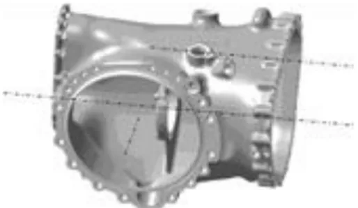
The interfaces and the gear trains axes are driven by external publications, but all other features which need to define bearing locations, fixation holes or wall thickness are managed locally by the designers. The parametric modeling of complex housings is still a field on which the design methodology has to be improved in order to easily generate a full 3D solid model.
6. Conclusions
The development of this parametric approach has brought many benefits in the lead-time reduction and in the quality of Eurocopter gearboxes conceptual design. Even if there is a huge benefit for MGB concept generations, a design choice is also highly linked with concept evaluations that will be mainly based on deflection and stress analyses. Therefore one of the next challenges for Eurocopter is the propagation of the design parameters not only in the CAD model, but also in finite elements models (FEM) (Fig. 6).
Mastering a parametric approach that links the CAD model, the meshing, the loads and boundaries conditions are new challenges that can significantly contribute to mechanical design lead time reduction.
References
´ ˜
¨ ¨
[1] Meier H, Roy R, Seliger G (2010) Industrial Product-Service Systems-IPS2
. CIRP Annals Manufacturing Technology 59/2:607–627.
[2] Ullman DG (2003) The Mechanical Design Process. Mc Graw Hill. pp. 137–173. [3] Wientahl HP, Stritzke H (1998) Logistic Orientated Product Design. Journal of
Materials Processing Technology 76:12–15.
[4] Andrews PTJ, Shahin TMM, Sivaloganathan S (1999) Design Reuse in a CAD Environment. Computers & Industrial Engineering 37:105–109.
[5] Chih-Hsing C, Mu-Chi S, Vincent CSL (2006) Computer Aided Parametric Design for 3D Tire Mold Production. Computers in Industry 57:11–25. [6] Sergio A, Duante C, Relvas J, Moreira R, Freire R, Ferreira JL, Simoes JA (2003)
The Design of a Washing Machine Prototype. Material and Design 24:331–338. [7] Jiang ZH, Yan JQ (2003) Research and Development of a Constraint-Based
Product Family Design and Assembly. Journal of Materials Processing Technology 139:257–262.
[8] Ma T, Tong T (2003) Associative Feature Modeling for Concurrent Engineering Integration. Computer in Industry 51:51–71.
[9] Ranta M, Matyla M, Umeda Y, Tomyama T (1995) Integration of functional and feature-daseb product modeling - the IMS/GNOSIS Experience. Computer Aided Design 26:371–381.
[10] Tomiyama T, Gu P, Jin Y, Lutters D, Kind Ch, Kimura F (2009) Design Meth-odologies: Industrial and Educational Applications. CIRP Annals Manufacturing Technology 58/2:543–565.
[11] Roy R, Hinduja S, Teti R (2008) Recent Advances in Engineering Design Optimisation: Challenges and Future Trends. CIRP Annals 57/2:697–715. [12] Ping Ge S, Lu C-Y, Suh NP (2002) An Axiomatic Approach for ‘‘Target
Cascad-ing’’ of Parametric Design of Engineering Systems. CIRP Annals Manufacturing Technology 51/1:111–114.
[13] Vaneker THF, Van Houten FJAM (2006) What-if as Synthesizing Working Method in Product Design. CIRP Annals Manufacturing Technology 55/1: 131–134.
[14] Lu C-Y, Suh N-P (2009) Complexity in Design of Technical Systems. CIRP Annals Manufacturing Technology 58/1:157–160.
T
I
D
)
(
F
[
$
]
G
Fig. 5. MGB housing with axes driven by external publications.Fig. 6. Example of MGB FEM analysis. 20