HAL Id: dumas-01841752
https://dumas.ccsd.cnrs.fr/dumas-01841752
Submitted on 17 Jul 2018
HAL is a multi-disciplinary open access
archive for the deposit and dissemination of sci-entific research documents, whether they are pub-lished or not. The documents may come from teaching and research institutions in France or abroad, or from public or private research centers.
L’archive ouverte pluridisciplinaire HAL, est destinée au dépôt et à la diffusion de documents scientifiques de niveau recherche, publiés ou non, émanant des établissements d’enseignement et de recherche français ou étrangers, des laboratoires publics ou privés.
Copyright
acid attacks
Sophie Travailleur
To cite this version:
Sophie Travailleur. Study of the durability of repair mortars submitted to acid attacks. Engineering Sciences [physics]. 2016. �dumas-01841752�
Escuela Técnica Superior de Ingenieros de Caminos, Canales y Puertos École Nationale des Travaux Publics de L’État
STUDY OF THE DURABILITY OF REPAIR MORTARS
SUBMITTED TO ACID ATTACKS
A Thesis in Materials engineering
by
Lucy Sophie TRAVAILLEUR
© 2016 Lucy Sophie TRAVAILLEUR
Submitted in Partial Fulfilment of the Requirements
for the Degree of
Master in Sustainable Territorial Planning Engineering
COMMITTEE
The thesis of Lucy Sophie TRAVAILLEUR was reviewed by the following:
Dr. Amparo MORAGUES TERRADES
Professor of science of construction materials
Teacher and researcher in the chemistry laboratory of the ETS de Ingenieros de Caminos, Canales, y Puertos
Tutor
Miguel A. de la RUBIA LOPEZ
Teacher and researcher in the chemistry laboratory of the ETS de Ingenieros de Caminos, Canales y Puertos
ABSTRACT
This study was carried out in order to acquire a better understanding of the behaviour of repair mortars when they are submitted to acid attacks. Above all, this study focuses on the case of an repair mortar that contains polymers. The main objectives of this study were to highlight the influence of the presence of polymers in the case aggressive agents attack the material, and to determine the parameters that main be responsible for the durability of the material. In order do so, three mortars were selected: two repair mortars (one containing polymers – the Monotop 412 SFG - and another one without polymer additions – the Monotop 412 S) and a conventional mortar (CEM 52.5 R) in order to make a comparison.
A first step consisted in characterising all of the mortars. Indeed, since repair mortars were used, there was a lack of information about their composition. Making a characterisation of each mortar was essential in order to predict and understand their behaviour when submitted to acids. All of the mortars were characterised from a mechanical point of view, as well as from microstructure and durability points of view. The different tests that have been carried out were: flexural and compressive strength tests, mercury intrusion porosimetry, differential thermal analysis, electrical resistivity, chloride migration and capillary absorption. The different tests have pointed out outstanding properties for the Monotop 412 SFG (which contains polymers) in terms of durability, even if no significant improvement was notices in terms of mechanical properties. They have also highlighted no improvement in the capacity of the Monotop 412 SFG to resist freeze/thaw cycle than a conventional mortar. This part has allowed highlighting that the Monotop 412 SFG has a microstructure that makes it more difficult for aggressive agents to penetrate into the material.
A second step consisted in submersing all of the three mortars into two different acid solutions (an acetic acid solution and a lactic acid solution). After one month of submersion, some characterisation tests were carried out in order to qualify the reaction of each mortar. From a visual point of view, it has been determined that the Monotop 412 SFG is the one that presents the best resistance to acid attacks in both cases (acetic acid and lactic acid). Indeed, for both solutions, theses samples were the least degraded after one month of attack. Moreover, the conventional mortar was the most deteriorated. It also appears that lactic acid attack is more intense for mortars than acetic acid attack is, in accordance with their pKa values. It attacked the gel, changing its stoichiometry, and leading to an increase in volume of the specimens. Three different tests were carried out in order to confirm these observations: mercury intrusion porosimetry, differential thermal analysis and a titrimetric method. However, the tests have pointed out a change in microstructure for both repair mortars while the conventional mortar was maintaining its microstructural properties. According to the tests, the properties of both repair mortars were worsened as a result of acid attacks. It can also be underlined that the results were worst in the case of lactic acid attack.
iv
TABLE OF CONTENTS
LIST OF ILLUSTRATIONS ... viii
LIST OF TABLES ... x
LIST OF EQUATIONS ... xi
ACKNOWLEDGEMENTS ... xiii
GENERAL INTRODUCTION ... 1
CHAPTER I: STATE OF THE ART ... 3
INTRODUCTION ... 3
1 PART I: REMINDERS AND GENERALITIES ABOUT CEMENTITIOUS MATERIALS 3 1.1 COMPOSITION AND STRUCTURE OF CEMENTITIOUS MATERIALS... 4
1.1.1 Reminders of cement chemistry notations ... 4
1.1.2 Cement ... 4
1.1.3 Additions ... 7
1.1.4 Aggregates ... 7
1.1.5 Water and additives ... 8
1.2 CHARACTERISATION ... 9
1.2.1 Hydration of the principal constituents of cement ... 9
1.2.2 Hydrated components of the solid phase ...11
1.2.3 Aqueous phase and porous structure ...14
1.2.4 Transport phenomena in porous materials ...15
1.3 CHEMISTRY OF CEMENTITIOUS MATERIALS ...19
1.3.1 Cement hydration process ...19
1.3.2 Kinetics of cement hydration ...20
2 PART II: MODIFICATION OF CEMENTITIOUS MATERIALS ...22
2.1 STANDARDS FOR THE REPAIR OF CONCRETE STRUCTURES ...23
2.2 COMPOSITION OF POLYMER-MODIFIED MORTARS ...24
2.2.1 Polymer latexes ...24
2.2.2 Redispersible polymer powders ...25
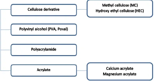
2.2.3 Water-soluble polymers ...26
2.2.4 Liquid polymers ...27
2.3 PROPERTIES AND CHARACTERISTICS ...27
v
2.3.2 Properties ...28
2.4 PREVIOUS STUDIES ABOUT POLYMER-MODIFIED MATERIALS ...28
2.4.1 Case of redispersible polymer powders ...29
2.4.2 Case of water-soluble polymers ...30
3 PART III: ACID ATTACK OF CEMENTITIOUS MATERIALS ...30
3.1 DURABILITY OF CEMENTITIOUS MATERIALS ...31
3.1.1 Generalities about the durability of cementitious materials ...31
3.1.2 Chemical attack of cementitious materials ...31
3.1.3 Case of organic acids ...33
3.2 MECHANISMS OF ORGANIC ACID ATTACKS ...35
3.2.1 Reminders about acid/base reactions ...35
3.2.2 Mechanisms of an attack by organic acids ...36
3.2.3 Consequences for the cementitious material ...37
3.3 PREVIOUS STUDIES ABOUT ORGANIC ATTACKS ...38
3.3.1 Studies on the effect of livestock manure and silage seepage ...38
3.3.2 Studies on the effect of pig slurry ...40
CONCLUSION OF THE CHAPTER ...40
CHAPTER II: EXPERIMENTAL APPROACH ...43
INTRODUCTION ...43
1 PART I: PREPARATION OF THE SAMPLES ...43
1.1 TYPES OF MORTARS ...43
1.2 DOSING AND PREPARATION OF THE SAMPLES ...45
1.2.1 Prismatic samples...45
1.2.2 Cylindrical samples ...47
1.2.3 Curing of the samples ...48
2 PART II: ACID MEDIUM ...48
2.1 CHOICE OF ACIDS ...48
2.1.1 Justification of the selected acids ...48
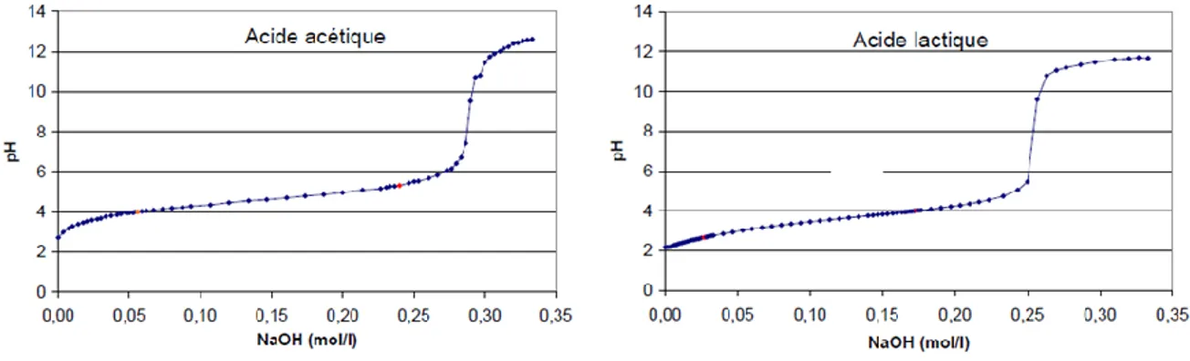
2.1.2 Characteristics of the selected acids ...49
2.2 PREPARATION OF THE ACID SOLUTIONS ...50
3.1 MECHANICAL PROPERTY CHARACTERISATION TESTING ...50
3.1.1 Flexural strength test ...50
3.1.2 Compression test ...51
3.2 MICROSTRUCTURE CHARACTERISATION TESTING ...52
3.2.1 Mercury intrusion porosimetry method (MIP) ...53
vi
3.2.3 Titrimetric method ...57
3.3 DURABILITY CHARACTERISATION TESTING ...58
3.3.1 Electrical resistivity ...58
3.3.2 Chloride migration...59
3.3.3 Capillary absorption ...60
3.4 TESTING PROGRAMME ...61
CHAPTER III: CHARACTERISATION AFTER HARDENING ...63
INTRODUCTION ...63
1 PART I: MECHANICAL PROPERTY CHARACTERISATION ...63
1.1 Flexural strength test ...63
1.2 Compression test ...65
2 PART II: CHARACTERISATION OF THE MICROSTRUCTURE AND THE DURABILITY...66
2.1 Mercury intrusion porosimetry ...66
2.2 Differential thermal analysis ...69
2.3 Electrical resistivity ...72
2.4 Chloride migration ...73
2.5 Capillary absorption ...75
3 PART IV: DISCUSSION ...76
CONCLUSION OF THE CHAPTER ...77
CHAPTER IV: RESISTANCE TO ACID ATTACKS ...79
INTRODUCTION ...79
1 PART I: DEGRADATION PROCESS ...79
1.1 Lactic solution ...79
1.2 Acetic acid ...82
2 PART II: CHARACTERISATION TESTING ...84
2.1 Titrimetric method ...84
2.1.1 Lactic acid ...85
2.1.2 Acetic acid ...86
2.1.3 Comparison ...87
2.2 Mercury intrusion porosimetry ...88
2.2.1 Lactic acid ...88
2.2.2 Acetic acid ...91
2.3 Thermogravimetric analysis ...94
2.3.1 Lactic acid ...94
vii
3 PART III: DISCUSSION ...98
CONCLUSION OF THE CHAPTER ... 100
GENERAL CONCLUSION ... 101
BIBLIOGRAPHIC REFERENCES ... 103
APPENDIX A – Principles defined in the EN 1504 Standard ... 107
APPENDIX B – Class of restoration mortars according to the performance characteristics 109 APPENDIX C – Extract from the product sheet of the Monotop 412 S ... 111
viii
LIST OF ILLUSTRATIONS
Figure 1 – Interface between an aggregate and the cement paste ... 8
Figure 2 – Structure of the silicates in the CSH gel ...12
Figure 3 – Calcium hydroxide crystal between calcium silicate hydrates ...13
Figure 4 – Dimensional range of solids and pores in a hydrated cement paste ...15
Figure 5 – Transport phenomena in concrete ...16
Figure 6 – Height corresponding to the capillary rise ...18
Figure 7 – Hydration process of Portland cement ...19
Figure 8 – Heat evolution during hydration process ...20
Figure 9 – Evolution of the hydration process in terms of amount of products formed ...22
Figure 10 – Classification of polymer latexes ...25
Figure 11 – Simplified model of the polymer-cement co-matrix formation ...25
Figure 12 – Classification of redispersible polymer powders...26
Figure 13 – Classification of water-soluble polymers (monomer) ...26
Figure 14 – Classification of liquid polymers ...27
Figure 15 – Model of composite mechanism ...28
Figure 16 – Relationship between concrete durability and performance ...31
Figure 17 – Deterioration of concrete by chemical reactions...32
Figure 18 – Repair mortars ...44
Figure 19 – Dimensions of the prismatic samples ...45
Figure 20 – Cylindrical samples for porosimetry and DTA ...46
Figure 21 – Dimensions of the cylindrical samples ...47
Figure 22 – Cylindrical samples ...48
Figure 23 – Titration curves for acetic and lactic acids ...49
Figure 24 – Loading device ...51
Figure 25 – Compression test device ...52
Figure 26 – A drop of mercury entering a pore ...53
Figure 27 – Mercury Intrusion Porosimetry device ...54
Figure 28 – Thermogravimetric and differential thermal analysis device ...57
Figure 29 – Chloride migration device ...60
Figure 30 – Experimental campaign ...61
Figure 31 – Failure of a repair mortar during the tensile test ...64
Figure 32 – Flexural strengths ...64
Figure 33 – Compression strengths ...65
Figure 34 – Differential intrusion and cumulative intrusion volume at 7 days ...67
ix
Figure 36 – Total porosity ...68
Figure 37 – Percentage distribution of pores ...69
Figure 38 - Tortuosity ...69
Figure 39 – Differential thermal analysis at 7 days ...70
Figure 40 – Differential thermal analysis at 28 days ...71
Figure 41 – Weight loss after 7 and 28 days of curing ...71
Figure 42 – Resistivity ...73
Figure 43 – Penetration depths ...74
Figure 44 – Migration coefficient ...74
Figure 45 – Capillary absorption coefficient ...75
Figure 46 – Evolution of the pH for lactic acid solution...80
Figure 47 – Mortars after 10 days of submission into lactic acid ...80
Figure 48 – Mortars after 1 month of submersion into lactic acid ...81
Figure 49 – Evolution of the pH for acetic acid solution ...82
Figure 50 – Mortars after 10 days of submersion into acetic acid ...83
Figure 51 – Mortars after 1 month of submersion into acetic acid ...83
Figure 52 – Mortars submitted to acetic acid after drying ...84
Figure 53 – DTA of the solid formed in the case of CEM I 52.5 R ...88
Figure 54 – PIM at the centre of the sample (lactic acid) ...89
Figure 55 – PIM on periphery (lactic acid) ...89
Figure 56 – Total porosity at the centre and in the periphery (lactic acid) ...90
Figure 57 – Tortuosity at the centre and in the periphery (lactic acid) ...90
Figure 58 – Pore distribution at the centre and in the periphery (lactic acid) ...91
Figure 59 – PIM at the centre of the sample (acetic acid) ...91
Figure 60 – PIM on periphery (acetic acid) ...92
Figure 61 – Total porosity at the centre and in the periphery (acetic acid) ...93
Figure 62 – Tortuosity at the centre and in the periphery (acetic acid) ...93
Figure 63 – Pore distribution at the centre and in the periphery (acetic acid) ...94
Figure 64 – DTA at the centre of the sample (lactic acid) ...94
Figure 65 – DTA on periphery (lactic acid) ...95
Figure 66 – Weight losses at the centre and in the periphery (lactic acid)...95
Figure 67 – DTA at the centre of the sample (acetic acid) ...96
Figure 68 – DTA on periphery (acetic acid) ...97
x
LIST OF TABLES
Table 1 – Cement chemistry notations for raw materials ... 4
Table 2 – Principal products of the cement production process ... 5
Table 3 – Types of cement according to the EN 197-1 Standard ... 6
Table 4 – Classification of additives according to the EN 934-2 Standard ... 9
Table 5 – Characteristics of the main components in cement ...11
Table 6 – Principal hydrated components of cement paste ...12
Table 7 – Characteristics of the main components of solid phase ...13
Table 8 – Classification of the porous network ...14
Table 9 – Parts of the EN 1504 standard ...23
Table 10 – Expected changes in the cement paste according to pH variation ...33
Table 11 – Some organic acids: formula and pKa ...34
Table 12 – Solubility of salts ...35
Table 13 – Formation constant for the Ca2+ cation (20°C) ...35
Table 14 – Intensity of the decalcification according to the pH ...38
Table 15 – Characteristics and origin of the mortars ...43
Table 16 – Water/solid ratios according to the mortar types ...44
Table 17 – Dosing for the preparation of prismatic samples ...45
Table 18 – Dosing for the preparation of cylindrical samples ...47
Table 19 – Formulas and pKa of acetic and lactic acids ...49
Table 20 – Identification of hydrated products according to the temperature ...55
Table 21 – Qualification of the chloride penetrability according to the electrical load ...58
Table 22 – Comparison of flexural strengths ...65
Table 23 – Comparison of compression strengths ...66
Table 24 – Comparison of water losses ...72
Table 25 – Comparison of resistivites ...73
Table 26 – Comparison of chloride migration coefficients ...75
Table 27 – Percentage of variation of the capillary absorption coefficient ...76
Table 28 – Diameters of the samples after 1 month of submersion into lactic acid ...81
Table 29 – Proportions of soda added to the solutions ...85
Table 30 – Quantity of CH formed in the lactic acid solution ...86
Table 31 – Calcium concentration in lactic acid solutions ...86
Table 32 – Quantity of CH formed in the acetic acid solution ...87
Table 33 – Calcium concentration in acetic acid solutions ...87
Table 34 – Comparison of weight losses (lactic acid) ...96
xi
LIST OF EQUATIONS
Equation 1 – Bogue’s equations for potential composition ... 6
Equation 2 – Equivalent binder ... 7
Equation 3 – Hydration of alite ... 9
Equation 4 – Hydration of belite ... 9
Equation 5 – Reaction of tricalcium aluminate with water ...10
Equation 6 – Decomposition of the reaction between tricalcium aluminate and water ...10
Equation 7 – Hydration of tricalcium aluminate in presence of gypsum ...10
Equation 8 – Hydration of tricalcium aluminate in presence of ettringite ...10
Equation 9 – Reaction of tetracalcium aluminoferrite with water ...11
Equation 10 – Hydration of tetracalcium aluminoferrite in presence of gypsum ...11
Equation 11 – Hydration of tetracalcium aluminoferrite in presence of ettringite ...11
Equation 12 – Darcy’s Law ...16
Equation 13 – Fick’s First and Second Laws ...17
Equation 14 – Jurin’s Law ...17
Equation 15 – Coefficient of capillary absorption ...18
Equation 16 – Reminders of an acid/base reaction ...36
Equation 17 – Partial dissociation of weak acids ...36
Equation 18 – Dissociation constant of a weak acid ...36
Equation 19 – Acceleration of the lixiviation of CH by H+ ion ...36
Equation 20 – Attack of the CSH by the H+ ion ...37
Equation 21 – Formation of calcium acetate salts ...37
Equation 22 – Formation of calcium lactate salts ...37
Equation 23 – Evolution of the pH of the acid solution toward the buffer zone ...50
Equation 24 – Determination of flexural strength ...51
Equation 25 – Determination of the compression strength ...52
Equation 26 – Washburn’s equation ...53
Equation 27 – Total porosity ...54
Equation 28 – Average pore diameter ...54
Equation 29 – Dehydroxilation of the calcium hydroxide ...56
Equation 30 – Carbonation of the calcium hydroxide ...56
Equation 31 – Decomposition of the carbonates...56
Equation 32 – Computation of the quantity of calcium hydroxide ...56
Equation 33 – Valuation of calcium by formation of a complex ...57
Equation 34 – Valuation of calcium by precipitation ...57
xii Equation 36 – Migration coefficient ...59 Equation 37 – Capillary absorption coefficient ...60 Equation 38 – Steps to the realisation of titrimetric method ...85
xiii
ACKNOWLEDGEMENTS
Firstly, I would like to thank the Escuela Técnica Superior de Ingenieros de Caminos, Canales y Puertos for allowing to realise my Master’s Thesis within their investigation laboratories. I had the chance to enjoy ideal working conditions with a good follow-up and overall, a great supervision. It has been an incredible experience that has surely made me grow and I have no doubts that it will be a real springboard in all my future endeavours.
I would like to have a special thank for my tutor Amparo MORAGUES TERRADES. She has accompanied me throughout this project and has given to me the necessary knowledge and some precious tips to achieve this Master’s Thesis. I also would like to thank my co-tutor Miguel A. de la RUBIA LOPEZ for all the help and support that he has kindly provided to me. I would like to thank Jaime C. GALVEZ RUIZ for his help and support when I was trying to define the subject and to find a tutor. I would also like to thank the company SIKA S.A. for having provided me the mortars that I used for this study.
I would like to thank all the people who work on both chemical and material laboratories for their kindness and their availability at all time. Especially, I would like to thank Arancha HUESO one hand and Alfredo CASERO on the other hand for having helped me with the experiments realised respectively in the chemical laboratory and in the material science laboratory. I would like to thank Angela MORENO BAZAN for having shared with me some precious tips and for having been there to answer all my interrogations.
Finally I would like to thank Cristina, Miguel, Selina, Encarnación and more generally everybody from both chemical and material laboratories (technicians, researchers, doctoral students, and teachers). They have all contributed to the good realisation of this Master’s thesis and I have learn from each of them.
1
GENERAL INTRODUCTION
Cement-based materials are ones of the most widely used in the fields of construction and civil engineering. The use of cement-based materials goes back over a period of several decades. The composition of these materials has evolved at the same time as the requirements from the industry have changed. Nowadays, cementitious materials are asked to be stronger and more flexible in order to fulfil both technological and structural demand from modern constructions. In this context, many different types of additions are now employed; among them are accelerators, filler additions or polymer-based materials.
Polymer materials have been used over centuries. They are now widely employed to produce materials and finished product for the industry. Construction industry has showed many interest in the combinations between polymers and cementitious material in the 1950’s – 1960’s, with the use of polymer concrete and polymer impregnated concrete. At that time, the improvement in physical properties of the final product was already demonstrate, which has reinforce the use of such materials for repair and bridge overlay. Later, in the 1970’s – 1980’s those materials have seen their used being increased in order to improve service life and strength of the structures. Indeed, depending on the types, polymers are known to improve particular properties, allowing thus satisfying new requirements.
Nevertheless, even if we are now able to produce high quality and high property cement-based materials, the question of its durability is still being essential to engineers and industrials which are looking for longer service life and less maintenance for the structures. Structure durability is a major factor in civil engineering as well as in industrial engineering, and this is closely linked to concrete durability (or that of any cement-based material which is used for the construction of the structure). The degradation of cementitious materials can have different sources. In particular, it can be due to the development of biological activity or to the influence of an aggressive medium. Many areas are concerned by the phenomena of deterioration of cement-based structures because of these types of attacks. Many studies have been carried out in order to understand the causes of such degradations and the mechanisms involved, in order to increase the durability of concrete in those cases. The cases of agricultural and agro-food industries as well as the case of biological activity have been especially studies over the past few years. However, to the best of our knowledge, this case has not been studied for polymer-modified concrete or mortars yet.
In the light of the above, this master’s thesis is the first step of a more general work which aims to provide a better understanding of this phenomenon in order to increase the durability of polymer-modified cementitious materials. Thus, the subject of this Master’s thesis has been defined collaboration with the IFTTAR (French Institute for sciences and technologies of Transportations, Planning and Networks) that I will join soon in order to deepen the investigations in the framework of a PhD-project. The main objectives of this Master’s thesis are the following:
2 - Understand the behaviour of those mortars in the case of an acid attack and the
influence of the presence of polymers in the composition of the mortars; - Identify the key parameters that help explaining the differences in behaviour.
To do so, three mortars will be considered, among which two repair mortars (one containing polymers, and another one formulated without polymers) that will be compared to a conventional mortar. They will be submersed into different acids in order to see the consequences of acid attacks.
This report will start by a bibliographical study that constitutes the first chapter. In it, a reminder of what is essential to know about cementitious materials will be done, including their composition, structure and characterisation. A focus will also be done on some aspects of chemistry of cementitious materials. Another part will focus on the modifications of cementitious materials, in particular on the case of the use of polymers. In this part, the different types of polymers that can be employed will be detailed as well as their properties. A summary of the main results of some studies for two different types of polymers will finally be made.
In the second chapter, the experimental approach will be detailed. We will begin with the preparation of the samples. In this part, we will characterise the mortars that have been selected, and how the mortars have been prepared in each case according to the type of the sample. The dosing used and the curing conditions will also be described. Another part will focus on the acid solutions. In this part, we will justify the choice of the two types of acids and give some data on them. We will then detail how the solutions have been prepared. Finally, the attention will be paid to the different tests that will be carried out, including mechanical tests, durability capacity and microstructure characterisation tests. The different test will be presented as well as the main result they allow accessing to. The machine used for each test and the Standard that have been applied will also be specified.
In the third chapter, the results that allow characterising all of the three mortars after their hardening will be presented. In this chapter, the mechanical properties will be regarded by the realisation of compression and flexural strength tests. With regard to the microstructure characterisation, the mercury intrusion porosimetry and the differential thermal analysis will be carried out. Finally, regarding the durability capacities, three tests will be carried out: electrical resistivity, chloride migration and capillary absorption. The results will be compared for all of the three mortars and a discussion will be made.
In the final chapter, the different mortars will be submitted to acid solutions. Two different solutions have been prepared and each mortar will be submersed in both solutions for one month. The effect of these attacks will then be highlighted by means of characterisation tests. In this part three tests will be carried out: mercury intrusion porosimetry, differential thermal analysis and a titrimetric method. The results obtained will be exposed and compared. A discussion will help pointing the main conclusions out.
Finally, a synthesis of all of the main results and conclusions will be made. We will also point out the future areas of investigation.
3
CHAPTER I: STATE OF THE ART
INTRODUCTION
Concrete is one of the most used materials. It is widely employed in civil engineering and in construction for its good resistance properties (above all against water, in comparison with steel, or wood), but also because of its cost. Over the past few decades, different processes have been put into place in order to improve the properties of concrete. Among them are the modifications of concrete by the addition of polymers. This type of modification is said to improve the performances of concrete and above all the resistance of concrete to chemical attacks.
Nevertheless, nowadays the structures made of concrete are more and more submitted to different types of attacks that lead to their degradation. These attacks are becoming more and more frequent due to favourable conditions (global warming, increase in the temperature worldwide). In particular, the effect of biogenic species has to be taken into account since the conditions are becoming favourable to their development. The effects of such attacks can be seen on the facades that suffer an important deterioration, or on some facilities that suffer degradation due to a wild environment. The action of such species is traduced by an acid attack of the structure, leading to its deterioration. To our best knowledge, this phenomenon has not been studied yet in the case of materials modified by the addition of polymers. However, in order to be able to apprehend such a study, it is essential for us to have some data about the mechanisms involved, and the previous studied that have been handled on traditional concrete.
In what follows, we will focus on the composition of a traditional concrete. We will also highlight the phenomena involved on the hydration process and on the transport process of the material. Then, we will focus on the different ways to modify it by adding polymers. Finally, we will focus on the attack of original cementitious material by organic species and the reported studies about this subject.
1 PART I: REMINDERS AND GENERALITIES ABOUT CEMENTITIOUS
MATERIALS
There are different types of cement-base materials. The first one, the cement paste, is made by mixing cement and water. The second one, the mortar, is obtained by combining fine aggregates (maximum aggregate size of 2mm) thanks to a hydraulic binder (which is the cement paste). The last one, the concrete, is obtained by combining both fine and coarse aggregates thanks to a hydraulic binder (which is the cement paste). This can be resumed by saying that cementitious materials are made with three main components, which are aggregates, cement and water, and some additives when necessary.
4
1.1 COMPOSITION AND STRUCTURE OF CEMENTITIOUS MATERIALS
1.1.1 Reminders of cement chemistry notations
Many different components enter into account in the composition of cement. In order to make easier the description of chemical composition as well as chemical reactions, a specific simplified notation has been developed, as shown below (cf. Table 1). This simplified notation is the one that will be used in this Master’s thesis.
NAME FULL NOTATION SIMPLIFIED NOTATION
Lime CaO C Iron oxide Fe2O3 F Alumina Al2O3 A Silica SiO2 S Sulphate SO3 Ŝ Water H2O H
Magnesium oxide MgO M
Sodium oxide Na2O N
Potassium oxide K2O K
Table 1 – Cement chemistry notations for raw materials
1.1.2 Cement
According to the European Standard EN 197-1, “cement is a […] finely ground inorganic material which, when mixed with water, forms a paste which sets and hardens by means of hydration reactions and processes and which, after hardening, retains its strength and stability even under water”.
Cement is one of the most important components that enter into account for the realisation of mortar or concrete. It plays an essential role in the behaviour of cementitious materials. Cement is a hydraulic binder, which is mainly made up from:
- Calcareous material which is the source of CaCO3 (it can also contain impurities such
as iron or alumina);
- Argillaceous material which is the source of SiO2, Al2O3, and some Fe2O3.
These two types of materials are the major contributors to the composition of cement; even though gypsum and eventually other mineral additives can take part of the composition of the cement.
Production process
The production process of cement consists in the grinding of the different raw materials into a fine powder, the mixing of the materials, and the burning in kilns at very high
5 temperature. This burning process leads to the production of clinker. Clinker will be then grinded with some additives, leading to the production of cement. The calcination process has several stages:
- Drying (up to 100°C): evaporation of free water.
- Preheating (100°C-750°C): evaporation of the water in the raw feed (clay) and changes in the crystal structure, leading to the activation of silicates.
- Calcination (750°C-1000°C): decarbonation of calcium carbonate (CaCO3).
- Burning (1000°C-1450°C): partial melting of the mix, formation of belite and appearance of a liquid phase which helps the reaction between belite and free lime, leading to the formation of clinker (cf. Table 2).
- Cooling of the clinker (1450°C-1300°C): crystallisation of the main liquid phase leading to the formation of aluminate phase (C3A and C4AF) and a little quantity of
belite (C2S).
NAME FULL NOTATION SIMPLIFIED NOTATION
Tricalcium silicate (alite) 3 CaO.SiO2 C3S
Dicalcium silicate (belite) 2 CaO.SiO2 C2S
Tricalcium aluminate (celite) 3 CaO.Al2O3 C3A
Tetracalcium aluminoferrite
(browmillerite) 4 CaO.Al2O3.Fe2O3 C4AF
Gypsum CaSO4.2H2O CŜH2
Table 2 – Principal products of the cement production process
Alite is the most abundant compound in the cement. It is in form of polygonal crystals which diameters are between 20 and 50µm. Belite is present in cement and, as well as alite, it is in form of rounded crystals. Tricalcium aluminate can adopt either a cubic form, or an orthorhombic form, depending on the sodium content. Finally, tetracalcium aluminoferrite is in the form of a solid solution (composed of massive and elongated crystals embedded in the interstice between alite and belite (OUESLATI, 2011)).
Principal constituents
Cements are made up with principal components, in which some secondary components are added. Gypsum is also often added in small quantities during the manufacturing of cement in order to regulate the cement setting. The principal components of cement are the following:
- Portland cement clinker; - Blastfurnace slag S; - Silica fume D;
- Natural pozzolana P and industrial pozzolana (i.e. natural calcined pozzolana) Q; - Siliceous fly ash V and calcareous fly ash W;
6 - Limestone L (that does not exceed 0.50% by mass) and LL (that does not exceed
0.20% by mass).
The secondary components are inorganic mineral materials. They can be natural or derived from the clinker production process. The percentages of these constituents define different types of cement, which are listed and classified in the EN 197-1 Standard, as shown below (cf. Table 3).
TYPES OF CEMENT CLINKER OTHER PRINCIPAL COMPONENTS SECONDARY COMPONENTS CEM I (Portland cement) 95 - 100% 0% 0 - 5% CEM II (Portland-composite cement) 65 - 94% 6 – 35% S/D/P/Q/V/W/T/L/LL 0 - 5%
CEM III (Blastfurnace
cement) 5 - 64% 36 – 95% Slag 0 - 5% CEM IV (Pozzolanic cement) 45 - 89% 11 – 55% D/P/Q/V/W 0 - 5% CEM V (Composite cement) 20 - 64% 18 - 50% S/P/Q/V 0 - 5%
Table 3 – Types of cement according to the EN 197-1 Standard
As seen in the table above, clinker is essential to the realisation of any type of mortar. According to the production process, there are four main phases that enter into account in the chemical composition of clinker: alite (C3S) which represents 40-60% of the chemical
composition, belite (C2S) which represents 20-30% of the chemical composition, and the
aluminate phase (C3A and C4AF) which represent 7-14% and 5-12% respectively. The
composition of each phase can be evaluated by means of Bogue’s Method. This method assumes that in the clinker, only these four phases are present, and defines the proportion of each phase (cf. Equation 1). It has to be underlined that the percentages obtained with this method are relative.
%𝐶3𝑆 = 4.0710 𝐶𝑎𝑂 − 7.6024 𝑆𝑖𝑂2− 6.7187 𝐴𝑙2𝑂3− 1.4297 𝐹𝑒2𝑂3 %𝐶2𝑆 = −3.0710 𝐶𝑎𝑂 + 8.6024 𝑆𝑖𝑂2+ 5.0683 𝐴𝑙2𝑂3+ 1.0785 𝐹𝑒2𝑂3
%𝐶3𝐴 = 2.6504 𝐴𝑙2𝑂3− 1.6920 𝐹𝑒2𝑂3 %𝐶4𝐴𝐹 = 3.0432 𝐹𝑒2𝑂3
7
1.1.3 Additions
Additions are finely ground materials (e.g. inorganic materials, pozzolanic materials or materials with a latent hydraulicity) which are added to cementitious materials in order to improve their physical and/or chemical characteristics. Additions are defined and characterised in the EN 206-1 Standard. Two main types of additions are identified:
- The substantially inert additions (type I);
- The pozzolana or latent-hydraulic additions (type II).
According to the European Standard, the performance of a concrete with an addition of mineral must be similar to the performance of a concrete without addition. To this end, the concept of equivalent binder has been introduced (cf. Equation 2). The EN 206-1 Standard defines the values of the coefficient K according to the addition which is used. It allows computing the water, taking into account the presence of additions (using the water/(cement + K x addition) ratio instead of the water/cement ratio). The values of K vary according to the country.
𝐿𝑒𝑞 = 𝐶 + 𝐾. 𝐹
Equation 2 – Equivalent binder
Where:
Leq is the amount of binder; C is the cement content per m3; F is the addition content per m3;
K is a weighted coefficient (depends on the addition).
1.1.4 Aggregates
Aggregates form the skeleton of the concrete. They are essential in order to obtain a good material from the point of view of dimensional stability, stiffness, abrasion resistance and economy. They are granular, inert and inorganic materials. The can be natural (i.e. made from minerals that come from alluviums or solid rocks that have only suffer mechanical transformations), artificial (i.e. made from minerals that are the result of an industrial process which includes thermal transformations among others), or recycled (i.e. after the treatment of an inorganic material previously used in the construction).
The grain size used is essential to obtain a good compactness. With regard to mortars, the maximum grain size used according to the EN 196-1 Standard is of 2mm. With regard to concrete, a mix of fine and coarse aggregates is used, and the proportions depend on the dosing chosen. Aggregates constitute 80% of a concrete, and 70% in the case of mortar, with respect to the total volume when hardened.
The interface between aggregates and the cement paste (cf. Figure 1) has a thickness of about some micrometres and is characterised by a water/cement ratio higher than the average in the paste. Consequently, in this area, the interfacial water is increased due to the surface exudation of the aggregates. So, the interfacial transition zone between the
8 aggregate and the cement paste matrix presents a particular interest since the adherence between the aggregate and the paste influences the resistance capacity of the material.
Figure 1 – Interface between an aggregate and the cement paste Source: (MEHTA & MONTEIRO, 1986)
1.1.5 Water and additives
Water is a well appropriated solvent for the realisation of cementitious materials (if those are inorganic material; in the case of mortars with a polymeric matrix, the solvent will be combined with the resin). Two types of water are used for the realisation of cementitious materials: the mixing water and the curing water. The first one enters into account in the cement hydration reactions, and gives a good workability to the cement. In this case, the dosage is essential since putting too much water will leads to an excessive porosity (which has a bad influence on the mechanical resistance), and putting not enough water will leads to a partial hydration of the material. The second one is used to allow the development of new hydration processes compensating the evaporation losses.
Additives (or admixtures) can be added while mixing the cementitious material components. Their function is to modify one or several properties of the final material. They can be either organic chemical compounds, or inorganic chemical compounds. They are incorporated respecting in general proportions which do not exceed 5% of the total cement weight. The improvements achieved with additives have an influence on both fresh and hardened states of the cementitious material. The EN 934-2 Standard classifies the additives according to their main functions (cf. Table 4).
FUNCTIONS ADDITIVES DETAILS
Modification of workability (rheology)
Plasticisers (water reducing); superplasticisers (high-range
water reducing)
Reduce water at equal consistence, or increase in consistence at equal
w/c ratio
9 hardening and setting Hardening accelerating
admixtures
Increase the development of initial resistances
Set retarding admixtures Increase the initial and final setting times
Modification of some particular properties
Air entraining admixtures
Entrain the formation of micro air-bubbles uniformly distributed into
the mass
Water retaining admixtures Reduce the bleeding Water resisting admixtures Reduce the capillary absorption
Table 4 – Classification of additives according to the EN 934-2 Standard
1.2 CHARACTERISATION
1.2.1 Hydration of the principal constituents of cement
Case of alite
Alite is in form of solid phase which forms a crystal lattice with impurities. This compound hydrates and hardens quickly. So, it has a high mechanical resistance at short age and it is responsible for initial set and high early strength in Portland cement. Alite reacts by means of an exothermal reaction producing calcium silicate hydrate gel and calcium hydroxide (cf. Equation 3). This mechanism can ben decomposed into the dissolution of C3S, the
precipitation of the silicate ions leading to the formation of calcium silicate hydrate, and finally the precipitation of the calcium ions in the form of calcium hydroxide.
2 𝐶3𝑆 + 6 𝐻 → 𝐶3𝑆2𝐻3+ 3 𝐶𝐻
Equation 3 – Hydration of alite
Case of belite
Belite is a compound which hydrates and hardens slowly. Thus, it has good long-term mechanical resistance and it contributes to strength at ages beyond seven days. Belite reacts by means of an exothermal reaction which evolves less heat than alite. As well as alite, it produces also calcium silicate hydrate gel and calcium hydroxide in fewer quantities than alite does (cf. Equation 4). It has to be underlined that several polymorphs of belite exist: α-C2S, αH-C2S, αL-C2S, β-C2S and γ. Nevertheless, only the β-C2S has significant
hydraulic properties (it is the dominant form in the Portland cement, which is the most commonly used).
2 𝐶2𝑆 + 4 𝐻 → 𝐶3𝑆2𝐻3+ 𝐶𝐻
10 Case of the aluminates
Aluminates compose the phase which is the most reactive towards water. This phase reacts quickly. This rate has to be controlled so that the cement can be shaped.
The tricalcium aluminate (C3A) contributes a little to the early strength development. It
releases an important amount of heat during the first few days. Its hydration depends on the presence of gypsum. The tricalcium aluminate is normally highly reactive. In presence of water, it reacts to produce a stable hydrate: the cubic hydragarnet (cf. Equation 5). This reaction can be decomposed in a two step-mechanism (cf. Equation 6). The first step leads to the formation of a hexagonal hydrate (C2AH8) and finally to the formation of the cubic
hydragarnet (C3AH6). The formation of the latest cubic structure is the one that allows the
hydration process continuing (MONTEAGUDO VIERA, 2014). The hydration process leads to different products in present of sulphates (coming from the gypsum).
𝐶3𝐴 + 6 𝐻 → 𝐶3𝐴𝐻6
Equation 5 – Reaction of tricalcium aluminate with water
2 𝐶3𝐴 + 27 𝐻 → 𝐶4𝐴𝐻19(𝐶4𝐴𝐻13) + 𝐶2𝐴𝐻8 𝐶4𝐴𝐻19(𝐶4𝐴𝐻13) + 𝐶2𝐴𝐻8→ 2 𝐶3𝐴𝐻6
Equation 6 – Decomposition of the reaction between tricalcium aluminate and water
As we may see, the presence of gypsum leads to the formation of ettringite crystals (cf. Equation 7). This reaction takes place until the gypsum is totally consumed (the gypsum is generally totally consumed before the tricalcium aluminate). It has to be underlined that gypsum causes a decrease in the rate of the reaction. At this stage, the tricalcium aluminate starts reacting with the ettringite (cf. Equation 8), which dissolution leads to the formation of calcium monosulfoaluminate hydrate (AFm). Consequently, the tricalcium aluminate has a great impact on the vulnerability of the cement to the sulphate attacks. That is the reason why the tricalcium aluminate content is approximately of 10% for cement, and 5% for the cements exposed to sulphate solutions (MONTEAGUDO VIERA, 2014).
𝐶3𝐴 + 3 𝐶Ŝ𝐻2+ 26 𝐻 → 𝐶3𝐴. 3𝐶Ŝ. 𝐻32
Equation 7 – Hydration of tricalcium aluminate in presence of gypsum
2 𝐶3𝐴 + 𝐶3𝐴. 3𝐶Ŝ. 𝐻32+ 4 𝐻 → 3 𝐶4𝐴Ŝ𝐻12
Equation 8 – Hydration of tricalcium aluminate in presence of ettringite
The tetracalcium aluminoferrite (C4AF) contributes slightly to strength but hydrates
quickly. It reduces the melting temperature of the raw materials in the kiln. The hydration process of the tetracalcium aluminoferrite is essentially the same as tricalcium aluminate, replacing the aluminates by aluminoferrites in the products of the reactions (cf. Equation 9, Equation 10 and Equation 11). It has to be underlined that in the case of tetracalcium
11 aluminoferrite hydration, the rate of reaction is slower than in the case of the tricalcium aluminate hydration process.
𝐶4𝐴𝐹 + 17 𝐻 → 𝐶3𝐴𝐻6+ 𝐶𝐹𝐻11
Equation 9 – Reaction of tetracalcium aluminoferrite with water
𝐶4𝐴𝐹 + 3 𝐶Ŝ𝐻2+ 30 𝐻 → 3 𝐶3𝐴. 3𝐶Ŝ. 𝐻32+ 𝐶𝐻 + 2 𝐹𝐻3
Equation 10 – Hydration of tetracalcium aluminoferrite in presence of gypsum
3 𝐶4𝐴𝐹 + 𝐶3𝐴. 3𝐶Ŝ. 𝐻32+ 12 𝐻 → 3 𝐶4𝐴Ŝ𝐻12+ 2 𝐶𝐻 + 2 𝐹𝐻3
Equation 11 – Hydration of tetracalcium aluminoferrite in presence of ettringite
Finally, we may say that gypsum plays an important role on the hydration process of the aluminate phase since it allows slowing down the reaction between the aluminates and the water while producing ettringite.
These characteristics can be summed up as show in the table below (cf. Table 5). Moreover, in terms of kinetics for the hydration process, the following relation can be established: C3A > C3S > C4AF > C2S. COMPONENTS HYDRATION SPEED HYDRATION HEAT MECHANICAL RESISTANCE CHEMICAL RESISTANCE
C3S High High High and rapid Acceptable
C2S Low Low High and late Good
C3A Instantaneous High Limited Very poor
C4AF High Low Limited Good
Table 5 – Characteristics of the main components in cement Source: (MASSANA GUITART, 2010)
1.2.2 Hydrated components of the solid phase
As seen above, the principal components of solid phase are the calcium silicate hydrate gel and the calcium hydroxide (Portlandite). However, other products are found in lower proportions (cf. Table 6).
NAME FULL NOTATION SIMPLIFIED NOTATION
12
Calcium silicate hydrate gel xCaO.ySiO2.zH2O CSH
Ettringite 3CaO.Al2O3.3CaSO4.32H2O C3A.3CŜ.H32 (AFt)
Calcium monosulfoaluminate
hydrate 3CaO.Al2O3.CaSO4.12H2O C4AŜH12 (AFm)
Table 6 – Principal hydrated components of cement paste
Calcium silicate hydrate gel
The calcium silicate hydrate gel is the main product of the hydration process and represents between 50% and 60% of the total volume of the hydrated cement paste. It is produced during the hydration of the silicates (tricalcium silicate and bicalcium silicate). It is the principal responsible for many properties of cementitious materials, including mechanical properties, hardening and durability. The CSH gel has a structure which is mainly amorphous and which can vary over time (many models have been realised to understand the morphology of the microstructure of the CSH gel but it still no being well defined). It has to be underlined that the stoichiometry of the CSH gel can vary according to its production mode (produced by the hydration of the silicates, pozzolanic reaction or synthesis). The bonds involved in CSH gels are ionic bonds; however, the bond linked Si-O is ionic and covalent at the same time. The silicon is at the centre of a tetrahedron whose apexes are four oxygens (cf. Figure 2).
Figure 2 – Structure of the silicates in the CSH gel Source: (MONTEAGUDO VIERA, 2014)
Calcium hydroxide
The calcium hydroxide crystals develop in form of a hexagonal network, and represent between 20% and 25% of the total volume of the hydrated cement paste (in the Figure 3 below, the calcium hydroxide is represented with an X, the CSH gel with a # and the pore with a 0). An important parameter in the morphology of the calcium hydroxide is the water/cement ratio. The forces evolved in the bonds are weak. Thus, calcium hydroxide does not influence the mechanical properties of the hardened cement. However, it plays an important role in the alkalinity of the material. The calcium hydroxide may be important in the case of attacks by acid components, leading to the lixiviation of the material in contact with water.
13
Figure 3 – Calcium hydroxide crystal between calcium silicate hydrates Source: (REGOURD & HORNAIN, 1975)
Aluminate hydrates
The ettringite is part of the AFt family (i.e. Aluminate – Ferrite – tri, where “tri” is linked to the three moles of CaSO4), in which it represents the most important phase. It has the
structure of a hexagonal prism. In the Portland cement, the ettringite grows during the first hours of hydration, with a maximum at 24 hours. Then, the AFm phase starts to be produced while the ettringite content decreases.
The AFm phase (i.e. Aluminate – Ferrite – mono, where “mono” is linked to the mole of CaSO4) contains the calcium monosulfoaluminate hydrate. It presents a laminar structure
and may have a hexagonal form.
The characteristics of the main components in solid phase can be summed up in the following table (cf. Table 7).
COMPONENT PROPORTION IN CEMENT
PASTE VOLUME ORIGIN CHARACTERISTICS
CSH 50 – 60% Hydration of C3S and C2S Mechanical properties of resistance CH 20 – 25% Hydration of C3S and C2S
Alkaline reserve of the cementitious material
Ettringite 15% Hydration of C3A
and gypsum
Durability in sulphated media
14
1.2.3 Aqueous phase and porous structure
According to SEREDA’s study (SEREDA, et al., 1980) three different types of water contained in the cement paste can be identified: chemically-combined water, physically-bounded water (gel water) and free water (capillary water).
The chemically-combined water is the one which reacts chemically with the cement particles. In this case, the elimination of the chemically-combined water leads to the drying of the products and the decomposition of the hydrate products.
The gel water is located in the gel pores. This type of water is associated to the laminar structure of the CSH gel. Its elimination is linked to the shrinkage of the structure.
The capillary water is located in the capillary pores: either in the large ones or in the little ones. Its elimination is not linked to any change in the dimensions of the cement paste.
Cementitious materials are porous media with a solid phase and different types of voids that can be filled with air or solutions. The parameters involved in the formation of the porous structure of cementitious materials are the following: the degree of hydration, the water/cement ration, the amount of cement, or the compaction. Different studies have been realised and have allowed identifying and classifying the pores (cf. Table 8). If we refer to the table, the pores that influence the most the cementitious materials are the mesopores and the macropores since they affect the shrinkage, the permeability and the strength of the material.
IUPAC P. MEHTA, 1986 S. MINDESS et al, 2002
Name Size Name Size Name Size
Micropores Up to 2 nm Interparticle space between CSH sheets 1 nm to 3 nm Micropores “inter layer” Up to 0.5 nm Micropores 0.5 nm to 2.5 nm Mesopores 2 nm to 50 nm Small (gel) capillaries 2.5 nm to 10 nm Capillary pores (low w/c) 10 nm to 50 nm Medium capillaries 10 nm to 50 nm Macropores > 50 nm Capillary pores (high w/c) 3 µm to 5 µm Large capillaries 50 nm to 10 µm Entrained voids 50 µm to 1 mm Entrained air 0.1 mm to 1 mm
Table 8 – Classification of the porous network Source: (ALIGIZAKI, 2005)
15
Figure 4 – Dimensional range of solids and pores in a hydrated cement paste Source: (MEHTA & MONTEIRO, 1986)
According to the figure above (cf. Figure 4) the morphology of the porous structure plays an important role on the durability of the material. Indeed, interconnected pores and open porosity make easier the access and transport of both gases and liquids exposing the material to severe troubles.
Micropores (or gel pores) are those who stay in between the sheets of CSH gel. According to MINDESS’s classification (cf. Table 8) their sizes are in the range 0.5nm– 2.5nm. Their volume increases as hydration products grow. They may modify both shrinkage and creep of the cementitious material, but have no influence on the resistant capacity of the material, or on its durability.
Mesopores (or capillary pores) are formed during the hydration process, when voids are not filled in with hydration products or anhydrous cement. They change as the components hydrate. According to MINDESS’s classification, their sizes are in the range 2.5nm–50nm. Their sizes increase with the water/cement ratio, and depend on the amount of hydrated cement and the degree of hydration. They may affect the durability of the cementitious material, as well as its transport capacity (especially when an interconnected network is formed by the mesopores). In the case of mesopores, water has the possibility to freeze (which does not succeed with the micropores due to their sizes).
Finally macropores (or Hollow shell pores) are formed by the air bubbles which remain trapped. According to MINDESS’s classification, their sizes are superior to 50nm. They do not affect the permeability of the material and if they are not connected, they may not influence the durability of the material. However, they might negatively affect the mechanical resistance of the material. They can be avoided by realising a good compaction of the material.
1.2.4 Transport phenomena in porous materials
In porous materials, transport mechanisms help aggressive agents (liquid compound, gas compound or ions that are dissolved in an aqueous phase) to enter the material leading to its deterioration. The transport phenomena are realised through permeability, diffusion, capillary absorption or convection (cf. Figure 5).
16
Figure 5 – Transport phenomena in concrete Source: (Comité Euro-International du Béton, 1992)
Permeability
Permeability is linked to a pressure gradient, leading to the formation of a movement in the material. Thus, permeability occurs if a flux of the aggressive agent is created in the material. Regarding this mechanism, the form and structure of the pore (types of pores, size distribution) have a great influence. It has to be underlined that the water/cement ratio, as well as the curing process plays an important role for the permeability of the material (a low w/c ratio and a good curing process lead to a low permeability of the material). The gas permeability is the parameter to study in order to quantify the permeability due to a pressure gradient. Darcy’s Law (cf. Equation 12) is the basis for the determination of the permeability applies to a flux of fluid.
𝑣 = − 𝑘 µ .
𝜕𝑝 𝜕𝐿
Equation 12 – Darcy’s Law
Where:
17 k is the coefficient of permeability (m²);
µ is the dynamical viscosity of the fluid (N.s/m²); 𝜕𝑝
𝜕𝐿 is the variation of the pressure related to length L (N/m²/m).
Diffusion
Diffusion is related to a chemical potential gradient (concentration gradient) in a saturated or partially saturated material. Indeed, the presence of a concentration gradient in the specie leads to the creation of a movement. Consequently, a global transport occurs from the points of higher concentration to the points of lower concentration. Fick’s Laws describe the transport by diffusion in a saturated material (cf. Equation 13). The diffusion coefficient quantifies the transport capacity. It has to be mentioned that diffusion is a slow transport mechanism in comparison with permeability or capillary absorption. Yet, it can be rapid enough to cause the deterioration of the material.
𝐽 = −𝐷𝑒 .𝜕𝐶 𝜕𝑥 𝜕𝐶 𝜕𝑡 = 𝐷𝑒 . 𝜕²𝐶 𝜕²𝑥
Equation 13 – Fick’s First and Second Laws
Where:
J is the particle flux of the specie considered (mol.m-2.s-1); De is the diffusion coefficient (m².s-1);
C is concentration of the specie considered (mol.m-3).
Capillary absorption
In the case of capillary absorption, the liquid transport is due to surface tension of water (which acts on capillary pores). This mechanism is related to the porous structure as well as the humidity of the material. The combination of the surface tension, the atmospheric pressure and the electromolecular forces leads to the penetration and the movement of the liquid water within the porous material. The capillary rise depends on the radius of the pore and the density of the capillary liquid, as it is explained in Jurin’s Law (cf. Equation 14).
ℎ = 2. 𝛾
𝑟. 𝑔. 𝜌. cos 𝜃
Equation 14 – Jurin’s Law
Where:
18 γ is the surface tension of the interface (N.m-1
); r is the radius of the tube (m);
g is the acceleration due to gravity (m.s-2) ρ is the density of the liquid (kg.m-3); θ is the contact angle (rad);
Figure 6 – Height corresponding to the capillary rise Source: (NESTOR EDUARDO, 2015)
The weight of water absorbed per area unit can be determined by combining Darcy’s Law and Laplace’s Law (cf. Equation 15).
𝐶𝑎 = 𝑀 𝑆. √𝑡
Equation 15 – Coefficient of capillary absorption
Where:
Ca is coefficient of capillary absorption; M is the absorbed water mass (kg);
S is the surface of the basis of the specimen (m²); t is the time (s).
Convection
Finally, convection is a transport mode produced when two areas of the material have different temperature. In the hot area, the fluid tends to decrease its density (by increasing its volume). To homogenise its properties, the fluid moves from the hot areas to the cold areas.
19
1.3 CHEMISTRY OF CEMENTITIOUS MATERIALS
1.3.1 Cement hydration process
Cement hydration process is characterised by a succession of steps between the ions that come from the dissolved reactive products entering in contact with water, evolving dissolution, transport or chemical reactions. First of all, the dissolution occurs, leading to the formation of an aqueous phase. Then, the components are transported through the pores. The ions liberated during the dissolution will then precipitate (when saturated) leading to the formation of the hydrates.
Figure 7 – Hydration process of Portland cement Source: (SCRIVENER, 1984)
The figure above allows having a better understanding of the hydration process in cement (cf. Figure 7). The figure a. shows the different phases at the beginning. Then, in figure b. (during the ten first minutes of the hydration process), there is a reaction between the aluminates and the gypsum leading to the formation of a gel at the surface; then, ettringite (AFt phase) starts growing upon the gel. In figure c. (ten hours after the beginning of the process), the tricalcium aluminate produces the called “outer CSH”, which is CSH gel growing from the surface. At 12 hours, we have reached the cohesion point where the grains start to occupy the voids. In figure d. (18 hours), we can see that the tricalcium aluminate continues to react with the gypsum provoking more formation of ettringinte (as we mays see the needles of ettingite are longer) while the CSH gel starts to penetrate the grain. In figure e. (evolution after 13 days), at this stage, the tricalcium aluminate reacts with the ettringinte (since the gympsum has been totally consumed) leading to the formation of the AFm phase (calcium monosulfoaluminate hydrate); at the same time, the CSH gel continues to grow into the grain. Finally, in figure f. (2 weeks), we can clearly see the called “inner CSH” which is the CSH gel formed within the grain.
The cement hydration process can also be described by the two following periods: the setting and the hardening. The first one occurs once the water is put in contact with the cement during the first few hours. It consists of the increase in the cement paste consistency
20 until it reaches the properties of a solid. Both beginning and ending of setting define the rheological changes in the material. The hardening occurs after the setting.
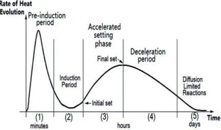
The hydration of cement evolves several steps. It is possible to have an idea of the different stages by measuring the evolution of the heat of hydration over time, as represented on the figure below (cf. Figure 8) that shows a typical evolution of heat over time for classical Portland cement. Each step will be described from the kinetics point of view in the following paragraph.
Figure 8 – Heat evolution during hydration process Source: (ZHANG, et al., 2015)
1.3.2 Kinetics of cement hydration
As it appears above (cf. 1.3.1) five periods can be identified.
Pre-induction period
This step occurs in the first minutes of the reaction (15 to 20 first minutes). The pre-induction period is characterised by the rapid dissolution of ionic species and the formation of the CSH gel on the surface while the C3S is being quickly dissolved. C2S reacts very little
during this period. C3A and C4AF react and lead to the formation of the AFt phase. The
precipitation of calcium hydroxide is the sign that the induction period is starting. This step is characterised by very fast rate kinetics and an important loss of heat (cf. Figure 8).
Induction period
Also called “dormant period”, it occurs in the first few hours of the reaction. At this stage, the reaction continues. The amount of calcium hydroxide increases until it reaches a maximum and then starts to be reduced. This period is characterised by a slowdown in the rate of reaction (cf. Figure 8). At this stage, the cement paste has plasticity and workability characteristics. Many different hypotheses have been emitted to explain the end of the induction period:
21 - A possible weakening of the barrier due to ageing;
- A possible diffusion of ions occurring across the barrier by osmosis; - A possible gradual weakening of the electrical double layer;
- A possible slowdown in the nucleation of calcium hydroxide due to the nuclei approaching their critical size.
Acceleration stage
This stage occurs between 3 and 12 hours after the mixing. At this stage, the C2S begins
to react significantly. The ions precipitate in the form of CSH gel and calcium hydroxide. The calcium hydroxide starts precipitating and the AFt phase continues to grow. During this period, the rate of hydration starts to increase again (cf. Figure 8). During this period, the cement starts setting. The end of this phase can be explained according to the following hypotheses:
- The nucleation and growth of the CSH gel; - The growth of a stable layer of CSH gel; - Break of the initial barrier;
- Nucleation of the calcium hydroxide.
Post-acceleration period
This stage occurs after 6 to 24 hours (for the cement made with clinker at normal temperature). AFt is converted into AFm. C2S increases substantially its contribution, which
leads to a reduction in the formation of calcium hydroxide. In general, the process starts to slowdown as it starts to be controlled by the diffusion (cf. Figure 8).
Diffusion
This stage is mainly controlled by the diffusion and transport processes within the porous matrix. Slow hydration reactions occur during the diffusion period. Even though its beginning and its end cannot be clearly defined, we can say that dense CSH gel structures (in comparison with those formed previously) are formed during this stage.
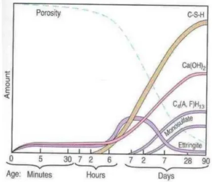
The process in terms of consumption and production of the different species can be summed up in the figure below (cf. Figure 9). Alite, as it is the main compound, determines to a larger degree the hydration process of cement. Indeed, alite is the principal responsible for the formation of CSH gel as explained above (cf. 1.2.1 and 1.2.2). As represented on the figure below, the CSH gel is the most important product of the hydration process; it is responsible for the resistance of the cement paste.
22
Figure 9 – Evolution of the hydration process in terms of amount of products formed Source: (Front Desk Architects, 2011)
Many parameters can influence the kinetics of the hydration process: - The composition of the phases of the cement;
- The quantity of gypsum in the cement and its form; - How fine is the cement;
- Water/cement ratio; - Curing conditions: - Hydration temperature; - Use of chemical admixtures.
The study of the kinetics of hydration process is carry out by the study of the degree of hydration (i.e. the fraction that has entirely reacted with water, relative to the total quantity of cement in the sample) related to the time.
2 PART II: MODIFICATION OF CEMENTITIOUS MATERIALS
Nowadays, in order to achieve the structural and technological requirements linked to the construction area, chemical additive are developed and used. Among them, the polymers are more and more requested. The basic reason why polymers are employed in cementitious materials is because they are able to modify both physical and chemical characteristics of the cementitious material (MILLER, 2005). They are particularly used for repairing and protecting the concrete structures.