Production of grey cast iron powder via target jet milling
Mohammad Ghambari
⁎
, Mahdokht Emadi Shaibani, Nicolas Eshraghi
School of Metallurgy and Materials Eng., University College of Eng., University of Tehran, Tehran, Iran
a b s t r a c t
a r t i c l e i n f o
Article history:
Received 28 October 2011
Received in revised form 13 December 2011 Accepted 12 January 2012
Available online 25 January 2012 Keywords:
Target jet milling Cast iron scrap Feed rate Impact angle Graphiteflakes
Target jet milling was used for thefirst time to convert cast iron scraps to powder. An experimental apparatus was designed which comprised a compressor, a mixing section, a nozzle, an impact chamber and two suction machines. Milling parameters i.e. the target to nozzle distance, the feed rate and the impact angle were optimized through appropriate tests. The travel distance of 8 cm and the impact angle of 90° were found to be ideal parameters of milling. The effect of feed rate on production of powders greater than 45μm was found to be opposite to the production of thefines (b45 μm). Investigation of the fragmentation procedure of particles revealed that, the existence of graphiteflakes in cast iron matrix plays the most important role in particle breakage.
© 2012 Elsevier B.V. All rights reserved.
1. Introduction
Air jet milling, or more commonlyfluid energy milling, uses high ve-locity jets of gas to impart energy to particles for size reduction. The car-rierfluid is usually compressed air, but nitrogen is often used in the pharmaceutical industry for its inert properties. In the mineral industry thefluid energy can be provided by steam[1]. Various types of jet mills have been reviewed by Rhodes et al.[2]and Chamayou et al.[1].
Target plate jet milling is a very common type of jet mill. In this type which is also calledfluid impact mill, particles are projected against a fixed target by a jet of gas[1]. The number of references dealing with impact on afixed target is numerous consisting both empirical re-searches[3,4] or numerical modelling studies[5–7]. The numerical analysis and modelling are based on Discrete Element Method (DEM). Although, DEM is a very popular technique used for a wide variety of applications, it is extremely difficult to truly validate DEM simulations. Attempts to quantitatively validate DEM simulations by comparing with experimental data are often frustrated by uncertainties in terms of the experimental data and the fact that frequently the simulated par-ticles are spheres and the experimental parpar-ticles are non-spherical[6]. Many milling parameters have been investigated by various re-searchers which could be categorized as follows:
1) Design parameters: impact chamber volume which should be big enough to avoid turbulence and determines the capacity of milling [1,8]; mixing unit geometry through which the particles disperse
into the gasflow[9,10]and geometry of nozzle which controls the velocity of particles[3,8,11].
2) Processing parameters: the pressure of the carrierfluid which determines the impact energy[12]; feed rate which defines the concentration of a jet and thus the particles interaction[8,10]; the impact angle which is the angle between the jet of particles and the target[12–14]andfinally the target material which its young modulus defines particle disintegration after impact[3,10]. In addition to jet mill design and milling conditions, the material properties are of crucial importance i.e. the mechanical properties of the material, its processing condition, the starting size or size distri-bution and the pre-existing imperfections andflaws in the material [15–17]. In spite of the crucial importance of material properties, the current understanding of the influence of material properties is very limited. This lack of information is reflected in the disappointing experience that each milling test with a new material has to start from scratch. Today no certain method exists to allow prediction or at least estimation of the milling behaviour of particles based on ma-terial properties[18].
The two most important applications of jet milling are in the phar-maceutical industry and granulation industry. Jet milling is common-ly used in the pharmaceutical industry where micronization is used to raise drug activity by increasing the particle specific surface area, or by allowing active substances to reach their site of action by reducing the particle size [11]. In the granulation industry, and during the granulation process, a relatively wide range of granule sizes are pro-duced whereas in most technologies the desired granule size range is rather narrow. The undersized particles are usually recycled to the granulation step while the jet milling of oversized particles is very useful due to theflexibility of the process[19].
⁎ Corresponding author. Tel.: +98 2188012999; fax: +98 2188006076. E-mail addresses:mgambari@ut.ac.ir(M. Ghambari),Mahdokht1364@yahoo.com
(M. Emadi Shaibani),Nicsh_2006@yahoo.com(N. Eshraghi).
0032-5910/$– see front matter © 2012 Elsevier B.V. All rights reserved. doi:10.1016/j.powtec.2012.01.020
Contents lists available atSciVerse ScienceDirect
Powder Technology
In the present work and according to the knowledge of the pre-sent authors, jet milling has been used for thefirst time to convert machining scraps of cast iron to powder. Detailed description of the designed apparatus and the series of experiments through which the milling parameters are optimized as well as the particle breakage mechanism are presented.
2. Experimental procedure 2.1. Grey cast iron scrap
The cast iron scrap investigated in this study was a pearlitic lamel-lar cast iron obtained during the dry machining of slabs used for mak-ing car engine components. The size range of the scraps was within 30 to 12 mesh (600–1700 μm). In order to observe the size reduction through the milling process more precisely, scraps with sizes out of this range were eliminated by means of sieving. Fig. 1 shows an SEM picture of the scraps used.
2.2. The experimental apparatus
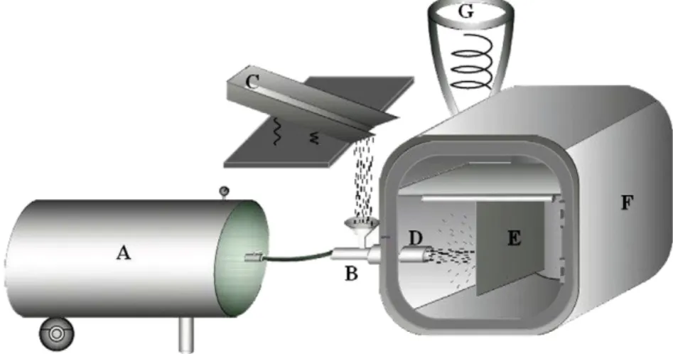
The experimental apparatus designed for this work is schematical-ly shown inFig. 2. The apparatus and the lateral equipment comprise 5 sections:
1. Compressor: An air compressor with the maximum pressure of 0.7 MPa was used to supply high pressure air for jet milling. 2. The air/particle mixing section: The high pressure air from
com-pressor was introduced to the mixing section, and at the same time the scraps were fed vertically in the stream of passing air by means of a vibratory feeder.
3. Nozzle: The type of nozzle which was found to be appropriate for this specific process was a straight nozzle with a particle travel dis-tance of 100 mm to an outlet of 20 mm in diameter. The straight geometry and the relatively large diameter of the outlet orifice were selected due to the shape and size of the original scraps used in this study.
4. Impact (milling) chamber: A steel chamber with the dimensions of 50 × 50 × 50 cm and round corners was made. A target plate was placed in an adjustable frame which could allow the movement of the target in both horizontal and vertical directions. The angle of impact could also be varied from 45° to 90°. The target was a 20 × 20 cm plate made of pearlitic gray cast iron. In order to avoid turbulence in the chamber, and to collect thefloating graph-ite particles separated during milling, a dust suction machine was attached to the chamber.
5. Particle collection and classification: A commercial vacuum cleaner was used to collect the milled particles from the chamber. The size analysis of the particles was done by sieving.
2.3. Optimizing the milling parameters
In order to optimize the milling parameters i.e. the target to nozzle distance, the feed rate and the impact angle, a series of tests were conducted. 200 g of scrap was used for each batch of tests. This was found to be an adequate amount for standard sieving procedure. The compressed air pressure was kept constant at 0.6 MPa through-out the tests. In order to obtain more reliable results at least two tests were carried out for every parameter investigated.
2.3.1. Optimization of the nozzle to target distance
In order to optimize the nozzle to target distance, jet milling was performed with 9 different distances at the impact angle of 90° and a feed rate of 40 g/s. The studied distances (from the outlet orifice of the nozzle to the target) were 2, 4, 6, 7, 8, 9, 10, 12 and 16 cm.
Fig. 2. Experimental apparatus: (A) compressor; (B) mixing section; (C) vibratory feeder; (D) nozzle; (E) target; (F) impact chamber; (G) suction machine. Fig. 1. SEM micrograph of cast iron scrap.
2.3.2. Optimizing the impact angle
Experiments were performed at various impact angles while other test conditions were kept constant, i.e. the optimum nozzle to target distance and the feed rate of 40 g/s. The studied impact angles (angle between the jet of particles and the target plate) were 50°, 60°, 70°, 80° and 90°.Fig. 3shows the schematic presentation of the change in impact angle.
2.3.3. Optimizing the feed rate
In order to investigate the effect of feed rate on the pulverization of the scraps, various feed rates of 40, 20, 10 and 5 g/s were tested. Other test conditions were kept constant i.e. the optimum nozzle to target distance and the ideal impact angle.
2.4. Effect of milling cycles
In order to observe the effect of milling cycles on the rate of size reduction, the amount of 1000 g of scrap was subjected to 5 cycles of jet milling at a feed rate of 40 g/s utilizing the optimized parame-ters obtained in previous tests.
2.5. Characterization methods
Standard sieving procedure according to U.S. Standard[20]was used to determine the size distribution of the original scraps and the produced powders. Scanning electron microscopy (SEM) was used to investigate the shape and size of the particles as well as their fracture surfaces. Quartering technique[21]was used to obtain representative samples for all characterization tests.
3. Results and discussion
3.1. Effect of the nozzle to target distance
Fig. 4shows the effect of the nozzle to target distance on the size reduction of the original scrap after one impact. The vertical axis of the plot inFig. 4represents the mass fraction of particles reduced to 60 mesh (b250 μm) after 1 cycle of milling from the original size of the scraps (30 mesh, >600μm). It is seen that by increasing the travel distance of the particles from 2 to 8 cm there is a gradual increase in the size reduction after which it starts to decrease as the distance ex-ceeds 8 cm. It seems that at the distance of 8 cm the particles are at
Fig. 3. Schematic presentation of the angle change between the nozzle and the target.
the maximum velocity on impact while at shorter distances the back splash of the particles from the target hinders the proper impact of all the particles onto the target. The loss of velocity could be the reason behind the decrease in size reduction at the distances greater than 8 cm.
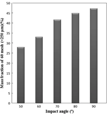
3.2. Effect of the impact angle
Fig. 5shows the effect of the impact angle on the size reduction of scraps. It can be seen that, by increasing the impact angle from 50° to 90°, the pulverization on impact intensifies. The effect of impact angle on particle breakage has been investigated by many authors, however these studies are either concerned with a dilute jet of particles where the particle velocity is independent of the jet concentration at a given gasflow rate[10,14]or they are of the type of numerical analysis [6,13]. Besides most of the investigations are based on spherical par-ticles as non-spherical parpar-ticles show great complexities. In contrast, the cast iron scraps used in this study were not spherical in shape and the jet of compressed air was saturated with particles, making parti-cle to partiparti-cle collision very important. It was shown above that, the highest impact velocity occurred at a nozzle to target distance of 8 cm. Therefore at the impact angle of 90° all particles traverse the 8 cm distance before impact causing maximum breakage to occur. By decreasing the impact angle and due to the cylindrical path of the particles shown inFig. 6, some of the scraps traverse less than 8 cm and some more than 8 cm to reach the target. This deviation from the optimum distance of travel for many particles lowers the overall pulverization effect. It is obvious that by decreasing the angle of incidence from 90° to 50°, deviation becomes more notice-able and less breakage occurs on impact.
3.3. Effect of the feed rate
The effect of feed rate on size reduction is shown inFig. 7. The be-haviour seen inFig. 7(a) concerning the 60 mesh (b250 μm) particles points to an increase of 13% by decreasing the feed rate from 40 g/s to 5 g/s. The interaction and collision of particles with each other and
Fig. 6. The actual photograph of the jet of particles inside the impact chamber showing the cylindrical path of the particles.
Fig. 7. Effect of the feed rate on production of: (a) 60 mesh (b250 μm) particles and (b)fines (b45 μm).
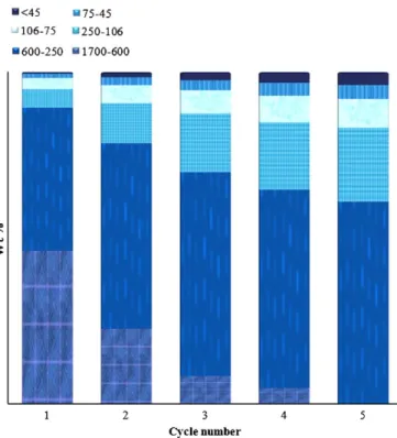
Fig. 8. Effect of milling cycle on the production of particles with different size distributions.
the wall of the nozzle increase by increasing the feed rate leading to a significant reduction of particles velocity and consequently less breakage of the particles on impact. HoweverFig. 7(b) shows that the production offines (b45 μm) goes through a different path, i.e. their production is at maximum when the feed rate increases to 40 g/s. The same phenomenon has been observed by Mebtoul et al. [10]. Considering these observations it can be postulated that in ad-dition to the breakage of the particles due to mechanical shock of impact, attrition mechanism also plays an important role. Produc-tion offines due to attrition can occur in two different ways: 1) Around the contact sites in nozzle which could be either the
noz-zle wall or points of collision with other particles. This mechanism operates more strongly at higher feed rates.
2) Around the impact sites which are more productive at higher im-pact velocities i.e. lower feed rates.
It can be postulated from the trend seen inFig. 7(b) that the pro-duction offines is dominated by the attrition mechanism taking place inside the nozzle. It could be explained by the fact that the contact sites of particles while travelling in nozzle are considerably more in comparison to contacts sites on impact.
3.4. Effect of milling cycles on the rate of size reduction
Observations made on the effect of milling cycles on the rate of production of particles with different size distribution are shown in Fig. 8. It can be seen that repeating the milling process will gradually lead to the production of particles with the desired size and size dis-tribution. In fact, this is a significant advantage of jet milling over the conventional ball milling of cast iron scraps. In jet milling of scraps, the online particle size analysis is possible which helps to pause the process when the required particle size is obtained, i.e. no further re-duction and no extra energy consumption.
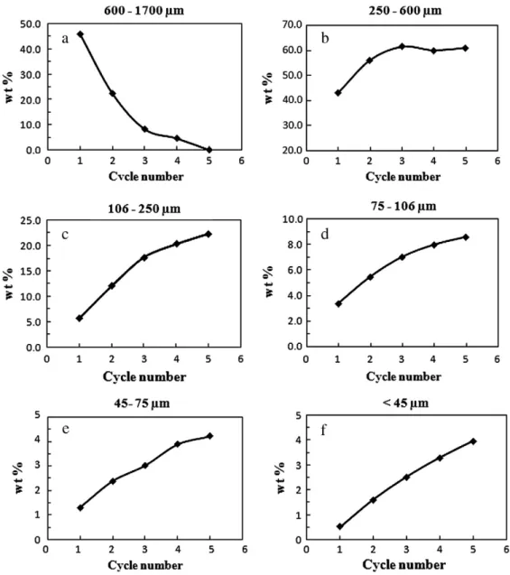
Production of smaller particles becomes harder as the process continues. The plots inFig. 9show this phenomenon in more detail. Plot (a) inFig. 9confirms that the first cycle is the most effective one where more than half of the original scraps (54%) are reduced from >600μm to b250 μm. Repeating the process for a second time there still remains more than 20% of 30 mesh (>600μm) scraps which indicates that fragmentation has become harder compared to the first step. Finally it took 3 more cycles for the 30 mesh (>600μm) particles to diminish completely.
Apart fromFig. 9(f), a levelling off pattern is seen in the rate of size reduction. This could mean that, pre-existing flaws in the
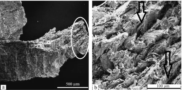
microstructure of cast iron scrap plays the most important role in fragmentation of this material under high velocity impact. The smal-ler the particles, a lesser chance offinding cracks with critical size needed for fracture to take place. Considering this fact, the smaller the particles get, the more they resist fracture. What is interesting in the case of cast iron which makes it distinct from other metal scraps is the type of theseflaws. In addition to the common flaws in cast metal scraps, cast iron matrix includes free graphiteflakes. Graphiteflakes act as internal notches and thus have an unfavour-able effect on the tensile strength and elongation at fracture. Cast iron with graphiteflakes has a strength range of between 100 MPa and 350 MPa, whereby the elongation at fracture drops from 0.8 to 0.3% as the strength increases. Cast irons with predominantly pearl-itic microstructure possess the highest strength and thus are very brittle[22].Fig. 10shows the fracture surface of a scrap after one cycle of jet milling. The macro voids marked onFig. 10(b), consider-ing theflaky shape and the length are most probably the places where graphite flakes were situated in the pearlitic matrix. The high velocity impact of scraps to the target would cause some of the graphite flakes to separate from the metal matrix and form voids which will either lead to material breakage at the veryfirst im-pact or weaken the material and lead to breakage on further imim-pacts. Otherflaws like tiny cracks might also join these voids and enlarge them. In fact this is mostly because of the various size of graphite flakes and their random distribution in the scrap matrix. That is, par-ticles with a wide range of size distribution are produced by the very first impact. It is also quite noticeable in plots d and h inFig. 9that not only do they show a decreasing rate of size reduction, but also the amount of particles produced after 5 cycles of jet milling is rather poor, especially for particles in range of 45–75 μm. This could be explained by the fact that, the graphiteflakes in the current material are mostly in the size range of 75–200 μm, thus their contribution to-wards fragmentation of such particles is minimized.
3.5. Analysis of particles collected in the dust suction machine
Particles which were collected in the dust suction machine after 5 cycles of jet milling were analysed and were found to be mostly graphite particles. This means that the floating graphite particles which were separated from the cast iron matrix during the milling process were sucked out. This simultaneous separation of the graph-ite particles from the powder particles during their production could be of great interest[23]. In addition to graphite particles, a small
amount of iron powder was also found in thefilter bag. In order to separate these particles from graphite for further analysis, a sample of powders were washed with acetone to remove the graphite. Wash-ing and decantWash-ing were continued until the acetone remained clear, after which the iron powder was dried. An SEM photograph of these particles is shown in Fig. 11. Iron powder particles as small as 74 nm were observed which were probably produced by the chipping of the initial scraps during thefirst cycle of milling attributed to the original shape of the scraps (Fig. 1).
4. Conclusions
1. It has been shown that jet milling could be used to produce cast iron powder with a wide range of size distribution from its scrap. 2. The nozzle to target distance of 8 cm proved to be the optimum
particle travel distance as it provides the highest impact velocity for the particles.
Fig. 11. SEM micrograph of powders collected in dust suction machine after 5 cycles of jet milling.
Fig. 10. SEM fractographs of (a) a scrap fracture surface and (b) magnification of the section marked in (a), the arrows point to places where graphite flakes most likely had been situated in matrix.
3. Maximum breakage occurred at an impact angle of 90° corre-sponding to the optimum nozzle to target distance for all traveling particles.
4. The pulverization rate increases with increasing feed rate for par-ticles larger than 45μm while the rate of production of fines (b45 μm) decreases.
5. Attrition and chipping in nozzle and on impact are the two domi-nant mechanisms by which production offines (b45 μm) during jet milling of cast iron scrap take place, with the former having a more pronounced effect.
6. Size reduction becomes harder as the milling continuous due to the loss of the graphiteflakes which are the major fracture sites in thefirst cycles of milling.
Acknowledgement
The authors would like to thank the“Industrial Development and Renovation Organization of Iran (IDRO)” for their financial support. References
[1] A. Chamayou, J.A. Dodds, Air Jet Milling, in: A.D. Salman, M. Ghadiri, M.J. Hounslow (Eds.), 1st ed., Handbook of Powder Technology, vol. 12, Elsevier, Amsterdam, 2007.
[2] J. Rhodes, Introduction to Particle Technology, 2nd ed. John Wiley & Sons, England, 2008.
[3] S.M. Tasirin, D. Geldart, Experimental investigation onfluidized bed jet grinding, Powder Technology 105 (1999) 337–341.
[4] O. Lecoq, N. Chouteau, M. Mebtoul, J.-F. Large, P. Guigon, Fragmentation by high velocity impact on a target: a material grind ability test, Powder Technology 133 (2003) 113–124.
[5] D. Eskin, S. Voropayev, O. Vasilkov, Simulation of jet milling, Powder Technology 105 (1999) 257–265.
[6] C. Thornton, S.J. Cummins, P.W. Cleary, An investigation of the comparative be-haviour of alternative contact force models during elastic collisions, Powder Technology 210 (2011) 189–197.
[7] G. Liu, S. Li, Q. Yao, A JKR-based dynamic model for the impact of micro- particle with aflat surface, Powder Technology 207 (2011) 215–223.
[8] S. Okuda, W.S. Choi, Gas-Particle Mixture Flow in Various Types of Convergent-Divergent Nozzle, Journal of Chemical Engineering of Japan 11 (6) (1978) 432–438.
[9] L.M. Hlaváč, I.M. Hlaváčová, P. Jandačka, J. Zegzulka, J. Viliamsová, J. Vašek, V. Mádr, Comminution of material particles by water jets— Influence of the inner shape of the mixing chamber, International Journal of Mineral Processing 95 (2010) 25–29.
[10] M. Mebtoul, J.F. Large, P. Guigon, High velocity impact of particles on a target an experimental study, International Journal of Mineral Processing 44–45 (1996) 77–91.
[11] N. Midoux, P. Hosek, L. Pailleres, J.R. Authelin, Micronization of pharmaceutical substances in a spiral jet mill, Powder Technology 104 (1999) 113–120. [12] Y.S. Cheong, A.D. Salman, M.J. Hounslow, Effect of impact angle and velocity on
the fragment size distribution of glass spheres, Powder Technology 138 (2003) 189–200.
[13] L. Liu, K.D. Kafui, C. Thornton, Impact breakage of spherical, cuboidal and cylindri-cal agglomerates, Powder Technology 199 (2010) 189–196.
[14] H. Dong, M.H. Moys, Experimental study of oblique impacts with initial spin, Powder Technology 161 (2006) 22–31.
[15] O. Lecoq, P. Guigon, M.N. Pons, A grindability test to study the influence of mate-rial processing on impact behaviour, Powder Technology 105 (1999) 21–29. [16] O. de Vegt, H. Vromans, J. den Toonder, K.V. Maarschalk, Influence of flaws and
crystal properties on particle fracture in a jet mill, Powder Technology 191 (2009) 72–79.
[17] J.A.S. Cleaver, M. Ghadiri, N. Rolfe, Impact attrition of sodium carbonate monohy-drate crystals, Powder Technology 76 (1993) 15–22.
[18] W. Peukert, Material properties infine grinding, International Journal of Mineral Processing 74 (2004) 3–17.
[19] A.W. Pacek, A.W. Nienow, An application of jet grinding tofluidized bed granula-tion, Powder Technology 65 (1991) 305–310.
[20] Annual Book of ASTM Standards; ASTM Designation: E 276– 98, American Soci-ety for Testing and Materials, West Conshohocken, PA, 2004.
[21] Annual Book of ASTM Standards; ASTM Designation: B 215– 96, American Soci-ety for Testing and Materials, West Conshohocken, PA, 2004.
[22] H. Berns, W. Theisen, Ferrous Materials: Steels and Cast Iron, 1st ed. Springer, Germany, 2008.
[23] M. Emadi Shaibani, M. Ghambari, Characterization and comparison of cast iron powder produced by target jet milling and high energy ball milling of machining scraps, Powder Technology 212 (2011) 278–283.