Transport Protocols: The Chameleon Protocol
Emmanuel Lochin
∗CNRS ; LAAS ; 7 avenue du colonel Roche, F-31077 Toulouse, France Universit´e de Toulouse ; UPS, INSA, INP, ISAE ; LAAS ; F-31077 Toulouse, France
E-mail: [email protected]
Guillaume Jourjon
NICTA, Locked bag 9013, Alexandria NSW 1430, Australia E-mail: [email protected]
S´
ebastien Ardon
NICTA, Locked bag 9013, Alexandria NSW 1430, Australia E-mail: [email protected]
Patrick S´
enac
CNRS ; LAAS ; 7 avenue du colonel Roche, F-31077 Toulouse, France Universit´e de Toulouse ; UPS, INSA, INP, ISAE ; LAAS ; F-31077 Toulouse, France
E-mail: [email protected]
Abstract: Rate-based congestion control, such as TFRC, has not been designed to enable reliability. Indeed, the birth of TFRC protocol has resulted from the need for a congestion-controlled transport protocol in order to carry multimedia traffic. However, certain applications still prefer the use of UDP in order to implement their own congestion control on top of it. The present contribution proposes to design and validate a reliable rate-based protocol based on the combined use of TFRC, SACK and an adapted flow control. We argue that rate-based congestion control is a perfect alternative to window-based congestion control as most of today applications need to interact with the transport layer and should not be only limited to unreliable services. In this paper, we detail the implementation of a reliable rate-based protocol named Chameleon and bring out to the networking community an ns-2 implementation for evaluation purpose.
Keywords:Transport Protocol, Protocol Implementation, Reliable rate-based Protocol, TFRC, SACK
Biographical notes: Emmanuel Lochin received his Ph.D from the LIP6 laboratory of Pierre and Marie Curie University - Paris VI in December 2004. He is currently researcher and network security officer at ISAE and is also member of the research group OLC (Tools and Software for Communication) of the LAAS-CNRS.
Guillaume Jourjon received his PhD from the University of New South Wales and the Toulouse University of Science in 2008 and a Engineer Degree from the ENSICA, a French aeronautical engineering school in Toulouse and a Master of Research in telecommunications and networking. He is researcher at NICTA.
S´ebastien Ardon received his PhD in Computer Science from the University Pierre et Marie Curie in Paris, at the Computer Science Laboratory of Paris 6 (LIP6). He is researcher at NICTA.
Patrick S´enac graduated from ENSEEIHT in 1983 and received the Ph.D. degree in computer science in 1996 from Toulouse University, France. Patrick S´enac is professor of computer science and head of the Mathematics, Computer Science and Control Department at the Institut Sup´erieur de l’A´eronautique et de l’Espace (ISAE) in Toulouse, France, and his also member of the research group OLC (Tools and Software for Communication) of the LAAS-CNRS.
Transport protocols suffer from an evolutionary pressure due to the large diversity of recently identified network properties. For instance, High Speed networks raise several performance problems in terms of throughput convergence (Floyd, 2003, 2004) while Delay Tolerant Networks are at the source of multiple new routing and end-to-end communications issues. As a result, the networking community shows a deep interest in rethinking the way to carry data over Internet. In particular, the IETF Transport Area Working Group (TSVWG) aims at specifying new congestion control and the recent Transport Architecture Evolution mailing list (TAE), discuss of ideas and issues surrounding the medium to long-term architectural evolution of the transport layer. Even the OSI model is now under question. Indeed, in a recent paper (Ford and Iyengar, 2008), the authors argue that the transport layer should be now sliced in three sub-layers to cope with new network characteristics.
Recent work on transport protocols, such as TFRC and DCCP (Handley et al., 2008; Kohler et al., 2006), have proposed alternatives to the generally used window-based congestion control in particular for multimedia applications. This idea is not new as the RAP protocol can be considered as the precursor in this area (Rejaie et al., 1999). However, the motivation behind was different. RAP’s goal was to slow down the development of application level congestion controls implemented on top of a UDP socket. Indeed, application-layer transport protocols might induce an increase of this new kind of “congestion-controlled” UDP traffic that would not strictly follow the fair-share principle introduced in (Jacobson, 1988) and might lead to a bad equilibrium of the Internet nay, a new congestion collapse. Thus, DCCP and TFRC compute a sending rate which reproduces the long-term TCP behaviour and have been defined as an alternative to UDP to carry multimedia traffic while respecting the fair-share principle introduced in (Jacobson, 1988). Compared to other contributions (such as TCP variants), DCCP is the first protocol that enables two classes of congestion control mechanisms (window and rate-based) which have been conceived to specifically target applications needs before network performances. Indeed, actual congestion control mechanisms only focus on the network congestion and do not take into account neither the application’s needs nor the new network services while DCCP includes multiple congestion control algorithms which can be selected in regards to the user needs.
In order to change between its different congestion controls, DCCP identifies them through Congestion Control ID (CCID). Three CCIDs are now being standardized by the IETF. CCID-2 (Floyd and Kohler, 2006) is a window based congestion control algorithm similar to TCP; CCID-3 (Floyd et al., 2006) mimics the TCP-Friendly Rate Control (TFRC) algorithm and CCID-4 (Floyd and Kohler, 2009) is an adaptation of
CCID-2 is appropriate to senders which would like to take advantage of the available bandwidth in an environment with rapidly changing conditions as bursty real-time traffic such as traffic from compressed encoded video and network games. CCID-3 is suitable for traffic with smooth changes in sending rates, such as telephony or video streaming.
Although Internet transport protocols have to be redesigned due to congestion control lack of fairness and the difficulty of TCP to achieve high throughput; other issues also arise in the context of wireless and lossy channels where rate-based solutions appears as natural candidates. Indeed, previous studies (Sharafkandi and Malouch, 2005; Kawadia and Kumar, 2005) have demonstrated the poor TCP performances over wireless and multi-hop networks while other emphasize the good behaviour of rate-based congestion control over these networks (Chen et al., 2004; Anastasia and Passarella, 2003). In the context of satellite communications, several studies have also demonstrated the benefit of using rate-based congestion control protocols compared to TCP window-based variants and in particular in (Lawas-Grodek et al., 2002), the authors present performances comparison between SCPS-TP, TCP, TCP-Vegas and rate-based protocols which clearly show the strong benefit obtained by the latter in terms of throughput efficiency over long delay links.
Therefore and following (Leiggener et al., 2006), the design of a reliable rate-based transport protocol is perceived as a suitable alternative to enable a transport reliable service over wireless multi-hop networks such as vehicular networks (VANET). The purpose of this paper is thus to present our design choices and challenges tackled in the implementation a reliable rate-based protocol named Chameleon (ns-2 source code is available upon request at http://manu.lochin.net/chameleon/ index.php). Firstly, we give in Section 2 the motivation and then in Section 3 the background of this work. We present the whole structure of this new protocol in Section 4, we detail major internal operations of the protocol in Section 5 and discuss other possible designs in Section 6. We demonstrate that the present composition of SACK and TFRC does not impact on the TFRC TCP-friendliness property and validate the flow control mechanism by showing that there is no packet lost at the receiver side in case of a slow receiving application (Section 7). Finally, Section 8 concludes this work and ns-2 implementation details are provided in Appendix.
2 Why
proposing
a
reliable
rate-based
protocol?
We believe that the possibility for the application layer (and even lower layers) to directly interact with the computed rate is a big step ahead but should not be limited to unreliable data communications. This capability, offered by TFRC, is a huge advantage to
enable efficient cross-layer mechanisms compared to the current Window per RTT metric used by TCP.As illustrated in XRTP (Gaonkar et al., 2007), another rate-based transport protocol proposal, the use of a rate-based congestion control also allows to ease the addition of either probing mechanisms to assess the bandwidth available or LDA (Loss Discrimination Algorithm) schemes to differentiate wireless from wired losses. As a matter of fact, several proposals have already taken advantage of this congestion control to realize cross-layer interactions between higher or lower layers. In particular, we identified the following contributions:
• VideoTFRC (Tan et al., 2008), where the authors improve the video applications thanks to an enhanced TFRC able to interact with the video codec. In (Gineste et al., 2009), the authors also present a method to enhance TFRC for video streaming by agnostically using applicative cross layer semantics and measures. A similar contribution where the authors propose Media-TFRC: a utility-based model using the rate-distortion function as the application utility measure for optimizing the overall video quality, is also described in (Yan et al., 2006);
• gTFRC (Lochin et al., 2006), where the authors detail the first congestion control mechanism which enables interactions between congestion control and DiffServ, in order to correctly guarantee the minimum throughput negotiated between the application and the QoS network (Blake et al., 1998);
• in (Armando et al., 2008), the authors propose a collaborative congestion control for emergency operations based on TFRC by giving access to the information provided by the transport layer; • Mobile TFRC (Zhang et al., 2008a,b), where the
authors specialize TFRC for mobile wireless LAN scenario with an interaction between the MAC and transport layers to increase the rate obtained by the mobile nodes.
All these studies, that demonstrate how cross-layer interactions can be easily enabled between the transport layer and upper or lower layers thanks to rate-based congestion control, motivate the present contribution which specifies a complete rate-based reliable transport protocol implementation as an alternative to the current domination of TCP in terms of reliable service. Thus, we claim that the combined use of TFRC and SACK can help to design new transport protocols as both mechanisms share the common goal of improving the QoS delivered to flows by offering respectively a mechanism for enhancing the smoothness of the flows rate variations and a mechanism for loss recovery. Their combined use, associated with their potential modification, offers a source of performance improvements that applications developers need.
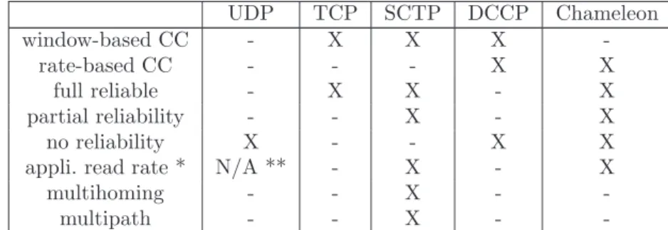
The capability to directly interact with the transport layer in order to either adapt the QoS required by applications and to enable or disable cross-layer mechanisms and reliability have motivated the name of this protocol: Chameleon. To clarify the position of Chameleon, Table 1 shows the gap filled by this proposal compared to other standardized protocols.
3 Background of this work
This section presents the background of this work and in particular, the SACK mechanisms used to enable full or partial reliability and the TFRC congestion control mechanism. Thus, the problems we have to solve with the Chameleon protocol are the following:
• design a flow control working together with the rate-based congestion control;
• design a reliable mechanism that interacts conjointly with the flow control and the congestion control;
• enable a rate-based congestion control that uses either reliable or unreliable services (although partial reliability can also be enabled, we do not tackle this case in the present study).
3.1 Selective Acknowledgment: SACK
There exists a range of reliability mechanisms from basic stop and wait to the more advanced Selective Acknowledgment mechanism (Floyd et al., 2000b; Mathis et al., 1996). In (Jourjon et al., 2008), the authors outlined the design of a SACK-like mechanism, suited for rate-based congestion control such as TFRC (Handley et al., 2008). While TFRC offers a smooth traffic dynamic property to the network, on the application side, this congestion control allows a direct exchange between the transport and application layers. As already emphasized in the introduction, the metric used by both layers is identical (i.e. a sending rate in bits per second) and is not related anymore to the discrete and unusable value of window of packets per RTT.
This previous study (Jourjon et al., 2008) mainly focused on the benefit of using such a rate-based protocol to efficiently reach a negotiated throughput over a DiffServ network, but did not specify the whole mechanism that could be used over a best-effort network. Thus, in the present paper, we also consider the problem of flow control implementation, i.e. how to prevent packet loss at the receiver due to the receiving application not reading packet fast enough from the socket buffer allowing to present a complete protocol specification. Such flow control mechanism is mandatory to implement an efficient reliable transport protocol and require specific adaptations compared to the well-known TCP flow control version in order to be used conjointly with a rate-based congestion control mechanism. At
Table 1 Positioning Chameleon compared to other standardized protocols. UDP TCP SCTP DCCP Chameleon window-based CC - X X X -rate-based CC - - - X X full reliable - X X - X partial reliability - - X - X no reliability X - - X X
appli. read rate * N/A ** - X - X
multihoming - - X -
-multipath - - X -
-* Capability of the application to read the current transmission rate of the transport layer through a setsocketopt function.
** The rate at which UDP emits is driven by the application.
last, the design of this implementation is not static and allows enabling or disabling the reliable mechanism plugged into TFRC. On the contrary, except in a recent study proposing an unreliable TCP mechanism (TCP-UREL (Ma et al., 2007)) to offer an alternative to DCCP/CCID-2 mechanism (Floyd and Kohler, 2006), none TCP version allows to switch between a reliable and unreliable congestion control service.
3.2 TFRC receiver-based
In (Padhye et al., 1998), the authors proposed a model to estimate the TCP throughput:
X = s (RT T · q p·2 3 + RT O · q p·27 8 · p · (1 + 32 · p 2)) (1)
where s is the packet mean size of the communication, RT T is the round trip time of the connection, p is the packet loss rate of the network path and the RT O is the TCP retransmit timeout.
Compared to the model in (Mathis et al., 1997), this model does not assume the periodicity of loss events. This model has allowed the introduction of TFRC congestion control mechanism (Floyd et al., 2000a; Handley et al., 2008). This mechanism uses equation (1) and defines a more complete protocol for the beginning of the connection and the role of the both sender and receiver side. Indeed, at the beginning of the connection, the mechanism uses a slow start phase. This phase, as the TCP slow start, increases exponentially the sending rate at the reception of every feedback packet according to equation (2):
X = 2 ∗ Xprev (2)
Where Xprev is the previously computed rate. This
slow start phase stops when the sender received a non-nil estimation of the packet loss. This estimation is done at the receiver either by an inversion of the TCP throughput equation (1) when the first loss occurs or by a weighting moving average of the loss event (a loss event is defined as one or more packet lost during a period of one RT T ) interval (i.e. interval between two loss events).
This phase can start again in the transmission if the RT O timer is triggered.
The sender is responsible for the computation of the RT T and the estimation of the RT O. This component receives the information of the packet loss rate from the receiver through feedback packets that are supposed to be sent at least once per RT T . Then, as described above, the sender either applies the slow start equation (2) or the TCP throughput equation (1) and minimises the output by comparing it to twice the receiving rate which has been given in the feedback message.
3.3 TFRC sender-based
In (Handley et al., 2008), it is mentioned that the design of a sender-based version of TFRC would be possible without any further details about its implementation. In particular, this version has been proposed to solve a security issue known as selfish receiver behaviour. This security concern might occur when a receiver sends an under-evaluated value of the packet loss rate in order to obtain a higher bandwidth. Nevertheless, in the DCCP’s specification of TFRC (Floyd et al., 2006), section 8 proposes that the receiver sends back the loss intervals of the communication to the sender. Thus, the sender can check that the packet-loss rate computed by the receiver is accurate. In (Jourjon et al., 2007), the authors have proposed a specification of the TFRC sender-based variant and showed that this proposal effectively solves the identified security issue and is more efficient in terms of computation. However, another great interest of a sender-based version deals with the possibility to propose TFRC improvements without involving receiver side modifications. For instance, TCP, which is sender-based, allows to ease the deployment of novel TCP variants. Although this sender-based variant does not impact on the throughput performances of TFRC (Jourjon et al., 2007), we choose to base our proposal on the standard and “official” receiver-based implementation, for the sake of simplicity.
4 Specification of the Chameleon protocol
We present in this section the protocol used for the integration of a flow control and, in particular, the composition of the TFRC congestion control and SACK reliable mechanisms and modifications associated.
4.1 Modification of the SACK feedback packet
The concept of Selective ACKnowledgments (SACK) was originally introduced in (Mathis et al., 1996) as a TCP option that aims to optimize its reliable service by allowing a faster recovery in the case of a burst of lost packets (Floyd et al., 2000b). By sending selective acknowledgements, the receiver of data can inform the sender which segments or packets have been successfully received and which ones have to be selectively retransmitted.
The conception of Chameleon implies the modification and the definition of new fields in the TFRC data and feedback headers. In both headers, each field is either encoded over 4 or 8 bytes except for the proto ID (two bits), the type (two bits), processing time (one byte), and the SACK payload (variable length). We defined the datagram oriented SACK mechanism similarly to the stream oriented mechanism: the SACK payload, constituted by a sequence pair numbers. These pairs represent the edge of a continuous sequence of corrected received packets. The length represents the number of pairs in the SACK payload. Finally the Offset represents the sequence number of the first packet of the first pair.
As TFRC mandates a new sequence number for each packet sent, we have to introduce a new identifier: the Application Identifier (AID), to perform the reliability which is detailed in Section 4.1.1.
4.1.1 Application Identifier (AID)
The reason to use this AID number is that TFRC assumes that all data packets contain a sequence number that is incremented by one for each data packet sent. If a lost data packet is retransmitted, it is given a new sequence number that is the latest in the transmission sequence, and not the same sequence number as the lost data packet.
As a result, we need to introduce a separate identifier: the application identifier (AID). With this identifier, the receiver is able to detect retransmitted, delayed or lost data packets. Thus, each retransmitted data packet has the AID of the lost data packet and a new sequence number. TFRC cannot distinguish a new data packet from a retransmitted one, but the SACK and flow control mechanisms are able to identify it.
4.1.2 Retransmission of lost packets
In case the sender is not allowed to send more new data packets, it waits until it gets a feedback message
with non-zero window size. While the sender is blocked, it is still able to retransmit lost data packets. It is important that the sender is always able to retransmit packets which are indicated as lost by the receiver, because the receiver could wait for a missing data packet which prevents all the following data packets in the receiver’s buffer from their delivery to the application (to guarantee in-order delivery). So it might happen that the receiver is waiting only for one data packet and is not able to receive more data packets due to buffer overflow and consequently: advertise a window size of zero.
4.2 Chameleon data packet header
The Chameleon data packet header contains the following fields:
1. Sequence number: data packet’s sequence number. For simplicity, where security issue can be neglected, the initial sequence number (ISN) starts at 0. Otherwise the sender and receiver have to negotiate the ISN before data transmission. The sequence number is incremented by one for each packet transmitted;
2. AID: application identifier. As previously explained, this ID is used to distinguish correctly received from retransmitted or delayed data packets and identify missing packets due to loss. Furthermore, the SACK mechanism is based on AID and not on sequence number. Therefore acknowledgments or losses of data packets are reported in AIDs;
3. Timestamp: the time when the data packet is sent. It is used by the receiver to determine which losses belong to the same loss event (Handley et al., 2008);
4. RTT: estimated round-trip time of the sender. It is used by the receiver, along with the timestamp, to determine when multiple losses belong to the same loss event. It is also used to determine the interval size to compute the received rate, and to determine when to send feedback packets (Handley et al., 2008).
4.3 Chameleon feedback message header
Concerning the Chameleon feedback message header, we added some new parameters in order to exchange information for reliability and flow control.
Each Chameleon feedback message sent by the receiver contains information of the original TFRC feedback packet (Handley et al., 2008) (in bold characters) as well as information for the flow control and SACK mechanism (in italic bold characters).
1. Timestamp echo: the timestamp of the last data packet received. It is used by the sender to estimate the round-trip time;
2. Timestamp offset: the amount of time elapsed between the receipt of the last data packet at the receiver, and the generation of this feedback report; 3. Receive rate: the rate at which the receiver estimates that data was received since the last feedback report was sent;
4. Loss event rate: the receiver’s current estimate of the loss event rate: p;
5. Timestamp: the time when the feedback message is sent. It is used by the sender to avoid unnecessary retransmission in a too short time range;
6. Window: the amount of packets which the receiver is able to receive without being overwhelmed;
7. ACK: acknowledgment is the lowest AID which will be acknowledged by this feedback message (first element in the SACK vector). It is used by the sender to know which packets of the SACK vector belongs to which packets in the sender’s window. It is also used to identify loss of feedback messages (sender knows the next expected ACK ). In case of prior feedback message loss, the sender assumes that all packets up to the value of ACK are received correctly by the receiver and acknowledges them;
8. Length of SACK vector: tells the sender how long the SACK vector in the current feedback message is. This length may vary from 0 to the maximum size of the window;
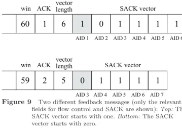
9. SACK vector: is a vector containing values of 1 (received) and 0 (not received, retransmit). All element of the SACK vector can be either 1 or 0, but the last element must be 1. Starting from the AID in ACK the sender knows which packets are received correctly and thus can be acknowledged, or which are lost and need to be retransmitted. In the rest of the paper, we refer to TFRC with the SACK mechanism and the complete protocol with flow control as Chameleon, and TFRC with only the SACK mechanism as TFRC-SACK.
Based on this composition, the design of a flow control mechanism compatible with TFRC is presented and validated in the following.
4.4 Flow control mechanism TFRC compatible
Since the SACK mechanism requires receivers to maintain a buffer for the in-order delivery of packet to the application, we base our design on the introduction of a new window variable: avail win, representing the space available in this buffer. This window should not be confused with the congestion-control window of TCP.Although the purpose of this variable is similar to
the TCP flow control algorithm (which is to maintain at the sender, the amount of buffer space available at the receiver and prevent the sender from transmitting more packets than there is available buffer space) the design is more challenging as a rate-based congestion control does not implement any control window. Furthermore, this new window variable cannot be compared to the DCCP Slow Receiver option (Kohler et al., 2006). Indeed, although this option mimic the behaviour of a flow control, this mechanism is just a simple threshold which avoids to overflow the receiver without sake of reliability. Other candidate solutions for the design, including modification of the TFRC equation, are discussed in section 6.
Figures 1 and 2 shows the sender and the receiver window. In this figure, the dark boxes represent data packets already sent or received.
10 11 12 13 14 15 16 17 18
left border right border
total window size
avail_win
Figure 1 The sender’s window. Left border: highest acknowledged packet ID; Right border: highest packet ID sent so far. avail win: available window size to send further data packets.
10 11 12 13 14 15 16
right border left border next left border
next SACK information total window size
avail_win
Figure 2 The receiver’s window. Left border: highest packet ID of the previously sent SACK vector; Next left border: highest packet ID of all correctly and in-order received packets. Right border: highest packet ID received so far. avail win: available window size to receive further data packets.
At the sender, the flow control mechanism should stop transmitting data packets if the receiver’s buffer is full. To achieve this, we use the avail win variable, which represents at the receiver side the available space in the buffer in number of packets. This variable is integrated in the TFRC-SACK feedback messages as a one-byte field. The avail win variable therefore indicates, at the sender, the supposed number of packets which can be sent. The avail win value is never negative and is upper bounded
by the total window size. When this variable is non nil, the sender sends data packets at the rate computed by TFRC algorithm. Each time a packet is sent, avail win is decreased by one at the sender. When avail win is nil, the sender has already sent the maximum number of data packets which could have been accepted by the receiver. Note that the TFRC rate still condition the speed at which packets are sent, the avail win variable condition the maximum number of packets which can be sent between receiving two feedback messages.
Indeed, as mentioned previously, each feedback message sent by the receiver contains the available buffer space. At the sender, upon reception of a feedback message, the avail win variable is computed by withdrawing the number of packets sent since the header’s Offset from the header’s avail win. A feedback message can therefore unfreeze the sender if the newly computed avail win is non nil or the SACK vector indicates that some packets need to be retransmitted.
At the receiver side, the flow control mechanism monitors the receiver’s buffer size and computes the availability to receive more new data packets. When a data packet is received, if its sequence number (Snew)
is higher than the highest previously received sequence number (Seqold), avail win is reduced by Seqnew− Seqold. Otherwise, this packet is out-of-order and is
therefore placed in the reception buffer. When the application reads packets from the buffer, the avail win is increased by the corresponding number of read packets.
5 Flow control in Chameleon
In this section, we illustrate the interaction of the flow control mechanism with the other mechanisms of Chameleon. These interactions are mandatory to integrate the flow control and the SACK mechanisms into the TFRC implementation.
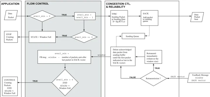
5.1 Source: sending operation (Figure 3)
When the application has a data packet to send, the flow control checks if there is available window (avail win > 0). If the source is allowed to send a packet, the flow control decreases the avail win by one and forwards the data packet to TFRC’s sending rate computation for transmission. The SACK mechanism inserts the data packet into a waiting data queue in order to retransmit it when considered as lost by the destination.
In case where avail win is zero, it means the sender has already sent the maximum number of data packets. Therefore the flow control mechanism blocks further reception of new data packets from the application.
5.2 Destination: receiving operation (Figure 4)
Once the data packet arrived at the destination, TFRC and SACK mechanisms update and compute their own
variables. For example, TFRC periodically computes the loss event rate and the receive rate, and the SACK mechanism identifies if the data packet is an expected, delayed or a retransmitted one and acknowledges its successful arrival by updating the SACK vector. However, the flow control is independent of the other mechanisms and does not need to be subsequent to the SACK mechanism. The flow control needs to know only the AID of the received data packet in order to update the avail win variable. If the AID (pkt.AID ) is higher than the highest AID of all previously received data packets (max AID ), then it decreases the avail win by their difference (max AID - pkt.AID ) and the received AID becomes the highest AID.
5.3 Destination: sending operation (Figure 4)
Every RTT (or after an RTT fraction, see Section 5.6), the destination triggers the feedback message transmission. During the creation of the feedback message, each mechanism sets its relevant values in the feedback message. The flow control mechanism advertises only its current avail win size to the source. The SACK mechanism sets the ACK, length of the SACK vector vec_length fields and appends the SACK vector whose length may vary for every feedback messages. For TFRC, the timestamp of the last received data packet (timestamp echo), the elapsed time between the time of data packet reception and time of the feedback message creation (timestamp offset), receive rate and loss event rate are set in the feedback message.
5.4 Source: receiving operation (Figure 3)
As soon as a feedback message arrives, each mechanism reads the values needed from the feedback message (i.e. flow control needs window and SACK needs SACK vector).
The flow control mechanism gets the latest available window size of the destination. However, the value of the advertised window size is not simply the avail win for the source. In order to compute the correct avail win, the flow control has to consider all sent data packets which were not received until the time of the feedback message creation. These data packets could still be delayed in the network and arrive just afterwards. Therefore, the avail win is the advertised window minus the number of all packets sent after the last data packet acknowledged by the feedback message (we clarify the acknowledgment and the window computation by an example in the next Section 5.5).
If the computed avail win is not equal to zero and the source was previously blocked, then the flow control mechanism still accepts new data packets from the application.
Data Packet
STOP Creating Packets
− number of packets sent after last packet in SACK vector .window
FB.msg
Delete acknowledged data packet from sending buffer (until the first packet indicated as lost in the SACK vector) Retransmit immediately (whatever the window size) Retransmission ? Data Packet Sent
STATE = Window Full
avail_win > 0 avail_win = avail_win − 1 avail_win == 0 avail_win = avail_win > 0 Window Full STATE == AND FLOW CONTROL TRUE TRUE TRUE APPLICATION CONGESTION CTL. & RELIABILITY TFRC X= f(p,RTT,s) at Sending Rate Sending Packet Window Full STATE != CONTINUE Creating Packets AND SACK Add packet to sending queue Sending Queue window TRUE FALSE Feedback Message SACK vector window SACK vector
Figure 3 Flow chart modeling of flow control at sender.
Pkt.AID > max_AID Data packet delivered to Application avail_win = avail_win + 1 FB.msg.window = avail_win Create/Update SACK vector Expected Delayed or Lost Packet expected AID pkt.AID > expected AID pkt.AID < Delayed or Retransmitted Packet CONGESTION CTL. & RELIABILITY Send Feedback Message window Data Packet TRUE APPLICATION FLOW CONTROL TRUE TRUE FALSE FALSE avail_win = avail_win − (max_AID − Data.AID) max_AID = pkt.AID
FBmsg.ack = AID of the first element in vector FBmsg.sack_vec=SACK vector FBmsg.vec_length = vector length SACK
Figure 4 Flow chart modeling of flow control at receiver.
5.5 Example of window computation at source
For the sake of simplicity, we assume in this example a total window size of 10 packets. Furthermore, we abbreviate the application identifier (AID).
15 16 14 17 11 12 13 18 Sender Receiver before 1 1 1 0 1 1 SACK vector 15 16 14 after 15 16 14 advertised_window = 7 new avail_win
Figure 5 Example: Acknowledgment and window computation at source.
Suppose the sender sends in sequence data packets from AID 11 to 18 (sender’s window before in Figure 5). All packets before 14 were correctly received and delivered to the application. Unfortunately, only the packet with AID 14 is lost during the transmission
(slashed in the receiver’s window ). After the reception of packet AID 16, the receiver sends a feedback message including a SACK vector [1, 1, 1, 0, 1, 1]. We recall the SACK vector contains values of 1 (received) and 0 (not received, retransmit). Every element except the last one can be one of these two values. The last element of each SACK vector must be always 1. If the last element would be 0, it means that the destination has detected a loss of data packets which might be eventually not sent at all. The bits set to one correspond to the successfully received data packets with AID 11 to 13, 15 and 16. The bit set to zero report the loss of the data packet with AID 14. The advertised window size in the feedback message is 7, because at the time of feedback message creation, there are two packets (AID 15 and 16) in the receiver’s buffer and one reserved for the lost packet (AID 14). Thus, three data packets occupy the receiver’s buffer. It is important to note that the receiver has detected the loss of the data packet with AID 14 and has reserved the space for later retransmission. Therefore, packets with
AID 15 and 16 must not be delivered to the application and need to remain in the receiver’s buffer in order to guarantee ordered delivery (this in-order service is a task of the SACK mechanism).
When the sender receives the feedback message, it has already sent the data packets up to AID 18. It acknowledges the data packets which are stated as correctly received (bits set to one) and removes them from the waiting data queue. Finally, only the packets which are waiting for their acknowledgment (AID 17 and 18) and which are lost (AID 14) remain in the sender’s window. This means the data packets with AID 17 and 18 did not arrive at the receiver before the creation of the feedback message and the data packet with AID 14 has to be retransmitted. Consequently, the sender must presume that the two data packets which were not in the SACK vector will be received correctly at the receiver and subtract them from the advertised window size. Thus, the new avail win size is the advertised window size minus the number of all data packets sent after the last data packet acknowledged by the feedback message (7 - 2 = 5 is the avail win). Thus, avail win corresponds to the difference between the advertised window and the number of packets sent after the last packet acknowledged by the SACK vector.
5.6 Choice of the frequency of the feedback
messages
The last problem we had to solve in order to provide an efficient flow control mechanism deals with the feedback frequency. TFRC requires at least one feedback message per RTT to maintain the sending rate. For Chameleon, we investigated whether more feedback messages are necessary following all these modifications and the impact of increasing this number of feedback messages. The frequency of receiving feedbacks regulates the waiting time of the sent data packets to be acknowledged at the sender. If this time is too long, then the sender can send packets slower, because there are many data packets waiting to be acknowledged and the sender’s available window might be zero.
The current TFRC RFC states that there is little gain from sending a large number of feedback messages per RTT. However in (Sarwar et al., 2008), the authors show that in long-delay contexts, such as satellite-based networks, the performance of TFRC can be improved by increasing the feedback frequency (Sarwar et al., 2008). In a deeper study (Lopez et al., 2009), the authors show that increasing the numbers of feedback per RTT may improve the perception of the congestion level parameters at the sender. The key at the origin of such improvement is an accurate value of the experienced RTT by the senders. Since a more accurate RTT value implicitly improves the drop rate seen by the receivers, this result in faster adaptation (high responsiveness) of TFRC to the network congestion levels. In (Lopez et al., 2009), the authors’ analysis have also shown that the improvements carried in by the increase of the feedback
frequency may have important effects on long-delay dynamic networks. Indeed, in short-delay networks, one feedback per RTT is enough to get an accurate RTT value. Also, in non-dynamic networks, the congestion avoidance mechanisms of TFRC which seek to avoid oscillations and losses events, limit the benefits of having a more accurate RTT value. Thus, the authors choose to set the default value to two feedback per RTT as a trade-off between long and short delay networks.
6 Discussion
The main feature of a rate-based congestion control mechanism is the use of an equation to determine the sending rate. This equation typically uses network measurements (or estimations) to calculate the theoretical rate at which TCP would send in similar conditions. Following this observation, we first investigated two other possible solutions to the flow control problem.
The first solution is to obtain the reading rate of the receiving application and to send it back to the sender. This can be done either by estimating the reading behaviour of the application or by assuming that the application can communicate this reading rate to the transport protocol. The sender would then adjust its sending rate to the minimum between its computed congestion control sending rate, twice the receiver’s receiving rate, and the application’s reading rate. However, this solution has two major drawbacks. Firstly, the reading rate depends on different parameters such as application type, CPU usage, etc. and may therefore follow complex patterns, which can be difficult to estimate. This may result in erroneous values leading in buffer overflow. Secondly, in order to provide packet ordering, the receiver temporarily buffers out of order packets. This can lead to a situation where the application’s reading rate is nil, therefore the sender would stop even if there is space in the buffer.
The second possible solution would have been to modify the equation used to compute the sending rate. TFRC computes its rate (X) with (1) following (Handley et al., 2008). As this equation is mainly driven by the RT T and the loss event rate (p). We simplify the notation of (1) with:
X = F (p, RT T ) (3)
We propose to model the flow control impact on the transmitting rate as follows:
X = F (p, RT T ) + G(avail win, p, RT T ) (4) where G(avail win, p, RT T ) is a model of the flow control impact on the transmitting rate which takes into account the avail win variable and F . However, we did not pursue this solution as it seems to introduce too much complexity inside the rate computation. Moreover, if we want to avoid losing packets at the receiver
due to a slow reading application, we would need to underestimate the sending rate, which would negatively impact on the protocol performance.
As a matter of fact, it follows that there is no gain to include the flow control in the TFRC’s sending rate algorithm.
7 Mechanism validation
In this section, we validate our Flow Control mechanism using simulation in ns-2.30. We first implemented the SACK-like mechanism within ns-2.30’s TFRC. We also extended the ns-2 simulator to include the application layer to simulate an application reading from the socket buffer at different rate. Using this implementation, we conduct a set of simulations to demonstrate the effectiveness of our flow control mechanism, and quantify the potential impact of the SACK and flow control modifications over the TFRC flow dynamics.
7.1 TCP-friendliness conservation and reliability
The first experiment aims at verifying the TCP-friendliness of Chameleon when sharing a bottleneck with other TCP flows. These days, the definition of the TCP-friendliness is still being debated (Briscoe, 2006). In this study, we will first follow the definition in RFC3448: “[...] a flow is “reasonably fair” if its sending rate is generally within a factor of two of the sending rate of a TCP flow under the same conditions.”. This definition concerns instantaneous values. Another common view is that, on average, a flow is TCP friendly if the non-TCP source obtains a long-run term average sending rate not larger than the one TCP would have obtained under the same circumstances (Floyd and Fall, 1999).
To quantify the TCP-friendliness we therefore use an expression of the means ratio as shown on equation (5):
T (X) = 1 n Pn i=1xi 1 m Pm i=1yi (5) where X is the protocol being studied, xi the average
throughput of the ith X flow, n the number of X flows,
yithe average throughput of the ithTCP flow and m the
number of TCP flows. In this formula if T is inferior to 1 then the non-TCP flow is TCP-friendly, if T is equal to 1 then we have an ideal friendliness and finally if T if greater than 1 then the non-TCP flow overruns TCP.
In this simulation scenario, we use the butterfly topology shown on Figure 6. There are two sources transmitting to two destinations over a shared link between two intermediate nodes. These two flows are competing for the bottleneck link bandwidth. We perform two experiments where Chameleon is first competing with TCP-SACK, then with TCP New Reno. All three protocols are set to the same packet size of 1KByte and a maximum window size 64KBytes. In both experiments, the application reading rate is infinite.
10 Mbits/s 10 Mbits/s 10 Mbits/s 10 Mbits/s 1 Mbit/s RTT=30ms between end−hosts Other protocol Chameleon protocol
Figure 6 Topology of the scenario
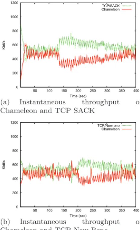
Results are presented in Figure 7. Each graph shows the flow instantaneous throughput at the receiver computed with an average sliding window throughput estimation with a 1ms window.
0 200 400 600 800 1000 1200 50 100 150 200 250 300 350 400 Kbit/s Time (sec) TCP/SACK Chameleon
(a) Instantaneous throughput of Chameleon and TCP SACK
0 200 400 600 800 1000 1200 50 100 150 200 250 300 350 400 Kbit/s Time (sec) TCP/Newreno Chameleon (b) Instantaneous throughput of Chameleon and TCP New Reno
Figure 7 Validation of Chameleon composition in ns-2.30
From Figure 7, we can see that the Chameleon flow instantaneous throughput is slightly inferior to both TCP SACK and TCP New Reno flows. In addition, the Chameleon instantaneous throughput is well within the 2x factor imposed by our TCP friendly definition previously mentioned. We can therefore conclude that this Chameleon implementation remains friendly with both TCP SACK and TCP New Reno. Several experiments with different RTT and bottleneck capacity have confirmed these results. For the sake of being concise, we give in this section a general sample of these experiments. In Figure 7 (a), Chameleon equally shares the bottleneck with TCP during almost 130s. At t = 130s, TFRC suffers from consecutive losses and therefore sharply decreases its throughput. Chameleon then attempts to re-adjust its throughput to the equilibrium with TCP, but this process converges slowly, which is a well-known shortcoming of TFRC (Widmer, 2000). When competing against TCP New Reno, as shown in Figure 7 (b), Chameleon behaves similarly to its behaviour with TCP SACK except that it stays
longer at the first equilibrium (200s instead of 130s). Furthermore after the consecutive losses Chameleon reaches the equilibrium with TCP New Reno faster than with TCP SACK. These differences can be explained as the TFRC equation models TCP Reno.
Table 2 presents the TCP-friendliness index of Chameleon calculated using equation (5). As all figures are below one. This confirms that TFRC-SACK is friendly with both version of TCP.
Table 2 TCP-friendliness index results
TCP version T(TFRC-SACK)
TCP/Newreno 0.82
TCP/SACK 0.72
For these experiments, we also validate the SACK mechanism, i.e. verify that all lost packets are retransmitted. In Table 3, we summarize the number of sent and lost packets for each flow in the previous experiments. We can see from this table that Chameleon flows send less packets than both TCP versions. This is explained as the TCP flows overall throughputs are higher than the TFRC-SACK and the packet statistics are collected during a fixed time period of 400s. Furthermore, we can see that the Chameleon flows experience less packets loss than both TCP flows (in absolute value and in percentage). This is explained by the fact that the rate-based congestion control mechanism produces a smoother sending rate compared to a window-based mechanism which is more aggressive. Finally, by using packet marking (not shown in the table), we verify that Chameleon retransmit all dropped packets until correctly received.
Table 3 Packets statistics
number of sent number of lost packets packet (percentage)
TCP/Newreno 26702 166 (0.62%)
Chameleon 21962 45 (0.2%)
TCP/SACK 28740 162 (0.55%)
Chameleon 20368 42 (0.2%)
7.2 Impact of the application read-rate
The objective of this experiment is to validate the flow control mechanism, by measuring the sender throughput when varying the application read rate, i.e. simulating a slower application. We also want to confirm that there is no packet lost due to a slow receiver unable to accept incoming packets. In addition, in this section, we quantify the impact of our SACK and Flow Control mechanisms over TFRC smoothness, by measuring the throughput smoothness during the data transfer.
In order to quantify this smoothness, we consider the average throughput for each time unit interval. For
each time interval we compute each flow’s throughput standard deviation (C. Jin and Low, 2004) and obtain the following metric equation (6):
S = 1 n n X i=1 1 xi v u u t 1 m − 1 m X j=1 (xi(k) − xi)2 ! (6)
where xiis the average throughput of the ith Chameleon
(resp. TFRC) flow, n is the number of flows, xi(k) is
the throughput of the ith Chameleon (resp. TFRC) flow
for the kth time interval and m is the number of time
intervals.
For these experiments, we use a simple topology where two nodes communicate through a third one. Packets are crossing two consecutive links of respectively 10 Mbps and 1Mbps bandwidth, for an overall 20 ms RTT (5ms delay on each link).
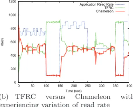
Figure 8 (a) shows the throughput of a Chameleon flow as the application read rate is set to 600kbit/s at the receiver. 0 200 400 600 800 1000 1200 0 10 20 30 40 50 Kbit/s Time (sec) Chameleon Drops
(a) Chameleon with read rate 600 Kbps, 20 ms RTT, queue limit of 10 packets (the cross represents six losses)
0 200 400 600 800 1000 1200 0 50 100 150 200 250 300 350 400 Kbit/s Time (sec)
Application Read Rate TFRC Chameleon
(b) TFRC versus Chameleon with experiencing variation of read rate
Figure 8 Validation of flow control mechanism
Each packet loss event is illustrated on Figure 8 (a) by a cross on the x-axis. At the beginning of the transmission, the sender sends packets according to the slow start algorithm. This phase stops when the first packet loss event occurs. TFRC then enters the congestion avoidance phase. As soon as the receiver’s buffer is full due to the application limited read rate, the sender can no longer send further packets. As the application reads from the buffer non nil avail win values are sent to the sender.
Hence, the sender is only allowed to send new packets when the receiver has delivered some packets to the
application. Consequently, Figure 8 (a) confirms that the flow control mechanism operates correctly as the throughput is adapted to the receiver application read rate. Furthermore, Figure 8 (a) shows that the receiver does not drop any packets.
In Figure 8 (b), we mix one Chameleon and one TFRC flow in the same network conditions as previously. However, contrary to the previous experiment, the application read rate varies in time and follows a specific pattern as shown in Figure 8 (b). We have chosen this specific pattern as it represents a mix of above, below and equal to the fair share throughput.
From Figure 8 (b), we can first see that a read rate above to the theoretical fair share value (500kbit/s) does not impact on the behaviour of Chameleon: TFRC and Chameleon equally share the link bandwidth. Furthermore, the transition from this read rate to another one inferior to 500kbit/s does not induce any packet loss at the receiver buffer. Between t = 100s and t = 150s, the application read rate is set to 100kbit/s, i.e. under the theoretical fair share value. During this phase, we can see from Figure 8 (b) that Chameleon sending rate is following the application reading rate while TFRC flow can uses the rest of the bottleneck. At t = 150s, the application reading rate is set again to values above to the fair share for 100s. We can see from the graph that during this period Chameleon and TFRC equally share the bottleneck bandwidth as expected. Finally, for the remaining variations of application reading rate, Chameleon continues to behave in a fair manner.
To quantify the impact flow control when the receiver application drives the transmission over the throughput smoothness, we use the smoothness metric, as defined in equation 6. We applied this criterion on a set of experiments that aims at checking that the flow control does not introduce any degradation in the smoothness characteristic of TFRC.
In Table 4, we present the results of experiment when two identical flows share a bottleneck of 1M bit/s during 400s. We show in this table that Chameleon remains as smooth as TFRC when it is not limited by the application read rate. Furthermore when we introduce for both flows a read rate of 300Kbit/s, the resulting smoothness of the system is increased. This result can be explained by the fact that the oscillations in the throughput are usually due to the congestion control mechanisms that tries to increase until the detection of a loss. In the case of a system limited by the application read rate the two flows do not try to increase nor decrease and therefore are more stable.
Table 4 Smoothness index for different protocols
TFRC Chameleon Chameleon read rate
S 0.094 0.097 0.051
8 Conclusion and future work
In this paper we have investigated and proposed a complete reliable rate-based protocol based on TFRC and SACK mechanisms. Our design also introduces a flow control variable, which regulates the sender to avoid packet loss at the receiver due to a slow receiver. We show that the modifications resulting from this composition does not affect the TCP-friendliness property of TFRC. We validate our proposal through ns-2.30 simulation and verify TCP-friendliness metrics. We further show that there is no packet loss due to flow control, at the receiver, and apply a smoothness criterion to demonstrate that the introduction of the flow control inside TFRC does not alter the smoothness property of this mechanism.
There is room for potential improvements. Indeed, although the present contribution only details and demonstrates the feasibility to implement a reliable transport protocol, several micro-mechanism can be designed to allow partial reliability or to help to answer to specific application needs. We hope to generate an interest from the networking developers’ community to use this protocol as a trade-off between application needs and network performances. We are currently working on a kernel implementation of this proposal inside the DCCP GNU/Linux implementation and are still improving our Java prototype (a Java implementation is also available upon request) for small devices such as PDA and cellular phones.
Acknowledgements
The authors would like to thank Yong-Han Lee (from EPFL during his internship) for the implementation of this proposal during his internship done at NICTA. Fr´ed´eric Bal (from ISAE during his internship) for the final and improved version of the Java version. Tanguy Perennou for many valuable remarks and advices about the presentation of this study. This work has been supported by funding from National ICT Australia.
References
Anastasia, G. and Passarella, A. (2003). Towards a novel transport protocol for ad hoc. In Personal Wireless Communications (PWC).
Armando, F., Wambeke, N. V., and Chassot, C. (2008). Introducing a collaborative congestion control based on TFRC. In Proceedings of the World Congress on Engineering and Computer Science (WCECS), San Francisco, USA.
Blake, S., Black, D., Carlson, M., Davies, E., Wang, Z., and Weiss, W. (1998). An architecture for differentiated services. Request For Comments 2475, IETF.
Briscoe, B. (2006). Flow rate fairness: Dismantling a religion. Internal report, ACM SIGCOMM CCR. C. Jin, D. X. W. and Low, S. H. (2004). FAST TCP:
motivation, architecture, algorithms, performance. In Proc. of IEEE INFOCOM, Hongkong.
Chen, K., Nahrstedt, K., and Vaidya, N. (2004). The utility of explicit rate-based flow control in mobile ad hoc networks. In Proc. IEEE Wireless Communications and Networking Conference (WCNC).
Floyd, S. (2003). HighSpeed TCP for Large Congestion Windows.
Floyd, S. (2004). Limited Slow-Start for TCP with Large Congestion Windows. RFC 3742 (Experimental). Floyd, S. and Fall, K. (1999). Promoting the use of
end-to-end congestion control in the Internet. IEEE/ACM Transactions on Networking, 7(4):458–472.
Floyd, S., Handley, M., Padhye, J., and Widmer, J. (2000a). Equation-based Congestion Control for Unicast Applications. In Proc. of ACM SIGCOMM, pages 43–56, Stockholm, Sweden.
Floyd, S. and Kohler, E. (2006). Profile for datagram congestion control protocol (DCCP) Congestion Control ID 2: TCP-like congestion control.
Floyd, S. and Kohler, E. (2009). Profile for Datagram Congestion Control Protocol (DCCP) Congestion ID 4: TCP-Friendly Rate Control for Small Packets (TFRC-SP) .
Floyd, S., Kohler, E., and Padhye, J. (2006). Profile for DCCP Congestion Control ID 3: TRFC Congestion Control. Request For Comments 4342, IETF.
Floyd, S., Mahdavi, J., Mathis, M., and Podolsky, M. (2000b). An extension to the selective acknowledgement (SACK) option for TCP. Request For Comments 2883, IETF.
Ford, B. and Iyengar, J. (2008). Breaking up the transport logjam. In in Seventh ACM Workshop on Hot Topics in Networks (HotNets-VII), Calgary, Alberta, Canada.
Gaonkar, S., Choudhury, R. R., Magalhaes, L., and Kravets, R. (2007). Designing a rate-based transport protocol for wired-wireless networks. In IEEE BROADNETS, Raleigh, Noth Carolina.
Gineste, M., Wambeke, N. V., and Exposito, E. (2009). Enhancing TFRC for video streaming by agnostically using applicative cross layer semantics and measure. In Second International Workshop of Future Multimedia Networking.
Handley, M., Floyd, S., Pahdye, J., and Widmer, J. (2008). Tcp friendly rate control (TFRC): Protocol specification. Request For Comments 5348, IETF. Jacobson, V. (1988). Congestion avoidance and
control. In Proc. of ACM SIGCOMM, pages 314–329, Stanford, CA.
Jourjon, G., Lochin, E., and S´enac, P. (2007). Towards sender-based tfrc. In IEEE International Conference on Communications (ICC).
Jourjon, G., Lochin, E., and S´enac, P. (2008). Design, implementation and evaluation of a QoS-aware transport protocol. Elsevier Computer Communications, 31.
Kawadia, V. and Kumar, P. R. (2005). Experimental investigations into tcp performance over wireless multihop networks. In In proceeding of the 2005 ACM SIGCOMM workshop on Experimental approaches to wireless network design and analysis.
Kohler, E., Handley, M., and Floyd, S. (2006). Datagram congestion control protocol (DCCP). Request For Comments 4340, IETF.
Lawas-Grodek, F. J., Tran, D. T., Dimond, R. P., and Ivancic, W. D. (2002). SCPS-TP, TCP and rate-based protocol evaluation for high delay, error prone links. In In Proc. of AIAA Spaceops.
Leiggener, A., Schmitz, R., Festag, A., Eggert, L., and Effelsberg, W. (2006). Analysis of path characteristics and transport protocol design in vehicular ad hoc networks. In In Proceedings of the 63. IEEE Semiannual Vehicular Technology Conference. Lochin, E., Dairaine, L., and Jourjon, G. (2006). gtfrc,
a tcp friendly qos-aware rate control for diffserv assured service springer telecommunication. Springer Telecommunication Systems Journal, 33(1-3):3–21. Lopez, D., Lochin, E., and Boreli, G. S. R. (2009).
Understanding the impact of TFRC feedbacks frequency over long delay links. In IEEE GIIS 2009 - Global Information Infrastructure Symposium, Hammamet, Tunisia.
Ma, L., Wu, X., and Ooi, W. T. (2007). TCP Urel, a TCP option for unreliable streaming. Tech. report, School of Computing, National University of Singapore. Available on line: http://nemesys.comp.nus.edu.sg/projects/tcpurel/. Mathis, M., Mahdavi, J., Floyd, S., and Romanow,
A. (1996). TCP selective acknowledgment options. Request For Comments 2018, IETF.
Mathis, M., Semke, J., Mahdavi, J., and Ott, T. (1997). The macroscopic behavior of the TCP congestion avoidance algorithm. ACM SIGCOMM Computer Communication Review, 27(3):67–82.
Padhye, J., Firoiu, V., Towsley, D., and Kurose, J. (1998). Modeling TCP throughput: A simple model and its empirical validation. In Proc. of ACM SIGCOMM, pages 303–314, Vancouver, CA.
Rejaie, R., Handley, M., and Estrin, D. (1999). Rap: An end-to-end rate-based congestion control mechanism for realtime streams in the internet. In Proc. of IEEE INFOCOM.
Sarwar, G., Boreli, R., Jourjon, G., and Lochin, E. (2008). Improvements in DCCP congestion control for satellite links. IEEE International Workshop on Satellite and Space Communications, 2008. IWSSC 2008.
Sharafkandi, S. and Malouch, N. (2005). Simple and effective end-to-end approach to increase TCP throughput over ad-hoc networks. In The 19th International Teletraffic Congress.
Tan, E., Chen, J., Ardon, S., and Lochin, E. (2008). Video TFRC. In IEEE International Conference on Communications (ICC).
Widmer, J. (2000). Equation-Based Congestion Control. Diploma thesis, University of Mannheim, Germany. Yan, J., Katrinis, K., May, M., and Plattner, B. (2006).
Media- and tcp-friendly congestion control for scalable video streams. Multimedia, IEEE Transactions on, 8(2):196–206.
Zhang, L., S´enac, P., Lochin, E., and Diaz, M. (2008a). Cross-layer based congestion control for WLANs. In ICST QShine.
Zhang, L., S´enac, P., Lochin, E., and Diaz, M. (2008b). Mobile TFRC: a congestion control for wlans. In IEEE International Symposium on a World of Wireless, Mobile and Multimedia Networks (WoWMoM).
A Implementation of Chameleon in ns-2
This part presents the main ns-2 issues and the related specifications of the exchanged messages, the application’s read rate variable and the treatment of the windows at the sender and receiver side.
A.1 TFRC-FC-SACK (Chameleon) Messages
There are two types of messages: TFRC-FC-SACK (Chameleon messages are named TFRC-FC-SACK in the ns-2 implementation) data packet and TFRC-FC-SACK feedback message. In the following, we shortly describe how the processing of the messages is implemented in ns-2. We pay a particular attention to the flow control and SACK mechanisms.
A.1.1 Data Packet
For a sake of simplicity, we assume the sequence number and the application identifier always start to 0 for each packet, so that no negotiation of these values is needed prior to the first data packet transmission.
For the flow control and SACK mechanisms, we introduced the application identifier (AID) in order to distinguish correctly received data packets from retransmitted or delayed ones.
We emphasize again that the integration of the flow control and SACK mechanisms did not change the functionality of the TFRC’s congestion control and its sending rate computation. As illustrated in the design of the flow control, the TFRC is a “black box” where flow control and SACK are added.
A.1.2 Feedback Message
In the feedback message, the relevant fields for the flow control and SACK mechanisms are: win, ACK, the SACK vector lengthand the SACK vector. We explain how the ACK variable is set depending on the first element of the SACK vector.
59
2
5
1
1
1
win ACK lengthvector
AID 4 AID 3 AID 5 SACK vector
1
0
AID 760
1
6
1
0
1
1
1
1
win ACK lengthvector SACK vector
AID 1 AID 2 AID 3 AID 4 AID 5 AID 6
AID 6
Figure 9 Two different feedback messages (only the relevant fields for flow control and SACK are shown): Top: The SACK vector starts with one. Bottom: The SACK vector starts with zero.
The ACK in the feedback message is the lowest AID normally acknowledged by the feedback message. It is
used by the source to determine which AID corresponds to the elements in the SACK vector containing 1 or 0 values. Furthermore, when previous feedback messages are lost, thus not allowing the source to acknowledge packets, the ACK indicates the correct reception of all data packets with AID up to this ACK value instead of the lost feedback messages.
During the feedback message creation at the destination, the SACK mechanism sets the value of the ACKfield depending on the value of the first element in the SACK vector. If the first element is 0 (bottom draw in Figure 9), the data packet with AID 3 is lost, the AID of the data packet just before the lost packet is chosen. It is mandatory that the ACK is not the AID of the lost data packet when it occupies the first position of the SACK vector. Indeed, the ACK must be the AID of a correctly received data packet. Thus, the first element corresponds to the data packet with AID equal to ACK + 1.
In the case where the first element is 1 (top draw of Figure 9), ACK is equal to the AID of the first element in the SACK vector.
To clarify, we present below a simplified code of the implementation.
At the destination, during the feedback message creation, we define the ACK as follows:
FB.ack = highestAIDsent_ + sackvec_[0];
where FB.ack is the ACK field in the feedback message, highestAIDsent is the highest AID sent in the previous feedback message (i.e. value of the AID of the first element minus one) and sackvec [0] is the value of the first element of the SACK vector (either 1 or 0).
At the sender side, in order to determine which AID corresponds to the elements in the received SACK vector, it is sufficient to know the AID of the first element of the received SACK vector:
if(sackvec_[0] == 1) then // first element is 1 firstElement_AID = FB.ack; else // first element is 0 firstElement_AID = FB.ack + 1;
where firstElement AID is the AID corresponding to the first element in the SACK vector, FB.ack is the ACK field in the feedback message, sackvec [0] is the value of the first element of the SACK vector (either 1 or 0).
We obviously notice that the SACK vector must end with one. Otherwise, it would mean that the destination states a data packet lost which might not been sent from the source. The destination detects a lost or delayed data packet only if it receives a data packet with a higher AID than the next expected one.
A.2 Application’s Read Rate
The application read rate corresponds to the rate of delivering packets from the buffer to the application. If
the destination is a low speed machine and receives a high-speed transmission of packets, then the buffer is used to store packets until the application can read and process them. We call this rate of reading from the buffer “application’s read rate”.
In ns-2, TFRC implementation is quite different from those of TCP or UDP. TFRC does not require to setup separate agents or applications. Instead, it creates a complete connection between the source and the destination nodes:
set tfrc [$ns create-connection TFRC $src TFRCSink $dst 0]
Therefore, we must simulate the application’s read rate in the implementation of TFRC-FC-SACK destination.
In order to perform simulations with different application’s read rates which is fixed in the TCL script, we bind the TCL’s read rate variable with the one in the C++ implementation. Furthermore, we introduce a new timer which calls the delivery function every time it expires. The read rate is initially given in kilobytes per second and converted in time per seconds in the C++ implementation in order to set the timer.
if(applreadrate = ’unlimited’) then applreadtime = -1;
// deliver as soon as pkt arrives // do not set the timer
else
applreadtime = (packetsize*8) / (1024*applreadrate); // packetsize in bytes, convert to bits // applreadrate in Kbps, convert to bits // per second
Finally, the frequency of calling the delivery function corresponds to the read rate of the application.
A.3 Sender’s Window, Receiver’s Window
The receiver’s window limits the buffer between the transport layer and the application layer. This stores packets when the application is busy and cannot read them immediately. The same happens if a previous packet is lost and the following packets cannot be delivered to the application in order to ensure in-order delivery. On the other side, the sender’s window limits the number of packets which can be sent to the receiver without overwhelming it. Both windows are built in a very similar way. In the following subsections the processing done on both windows are described.
A.3.1 Receiver’s Window
• sackedsofar: This variable is the application identifier (AID) of data packet acknowledged so far. This means all packets up to this AID are received correctly and in order (contains no gap of delayed or lost packets). All data packets having
10 11 12 13 14 15 16 17 18
total window size
19 20 avail_win max_aid
sackedsofar deliveredtoapp
Figure 10 Receiver’s window
AID up to this value can be delivered to the application;
• max aid: This variable always keeps the highest AID received at that time. If max aid is not equal to sackedsofar, then some packets having AID between sackedsofar and max aid are lost or delayed;
• deliveredtoapp: This variable indicates the last packet delivered to the application. This value cannot be higher than sackedsofar;
• avail win: Indicates the number of packets which can be received before the buffer is full. This value is sent in the feedback messages and advertises the current receiver window size to the sender; • total window size: The total size of the receiver’s
window. This is a constant value fixed to 65 packets (corresponds to 64 KB buffer size).
At the initialization, the avail win is equal to the total window size. Each time when in-order data packet is received, it is decreased by one. If there is a gap of data packets between the previously and the newly received ones, then the avail win is decremented by one plus the number of these missing packets. Whereas it is incremented by one, only if the application has read one data packet.
A.3.2 Sender’s Window
10 11 12 13 14 15 16 17 18
total window size
19 20
sackedsofar max_aid
avail_win
Figure 11 Sender’s window
• sackedsofar: This variable is the AID of the last data packet acknowledged. All packets up to
this AID are received correctly at the receiver, acknowledged and removed from the sender’s window as they do not need to be retransmitted anymore;
• max pkt aid: It keeps the highest AID created by the application so far;
• free window: Indicates the number of data packets the sender is able to send more;
• total window size: It is the total size of the sender’s window. Initially, it is set to 65 packets (corresponds to 64 Kbytes of buffer size).
When the sender receives a feedback message with the advertised window, it computes its available window size (avail win) with the following equation (except the advertised window is 0):
avail_win = adv_win (max_pkt_aid
-(sackedsofar + sackvec_length)) where adv win is the advertised window size in the feedback message, sackvec length is the length of the SACK vector in the feedback message.