To c CAR mod Gre This Epri Any adm cite this RDOSO delling o eece. s is an ints ID: 4 y corresp ministrato docume O Janette of multi author-d 4684 pondence or: staff-o ent: ADE e, SEGU i-physica deposited e concer oatao@in ELINE R UIN Ch al system d version rning thi np-toulo Romain, ristel. T ms. In: E n publis is servic use.fr , DARFE Toward ESREL shed in: ce should EUIL Pi a metho 2010, 0 http://oa d be sen ierre, HU odology 05-09 Se atao.univ nt to the UMBER for the ept 2010 v-toulous e reposito
RT Sophi
e AltaRi
0, Rhode
se.fr/ oryie,
ca
es,
1 INTRODUCTION
According to international airworthiness regulations, TURBOMECA has to demonstrate to authorities that its products (turboshaft engines) satisfy several safety requirements. Aeronautical standards propose practices widely accepted in order to demonstrate that a system is safe. In particular, ARP4754 (SAE 1996a) provides guidelines about processes that can support the safety assessment of complex systems. ARP4761 (SAE 1996b) recommends methods to as-sess the safety of a system such as Failure Modes and Effects Analysis (FMEA) and Fault Tree Analy-sis (FTA). This kind of analyAnaly-sis is performed to identify the scenarios leading to undesired events and to calculate the occurrence probability of unde-sired events.
However, if these analyses are still widely used in the industry, they have difficulties to take into ac-count the constraints inherent to new industrial sys-tems. First, the size and the complexity of current industrial systems increase. Moreover, they become more and more reconfigurable. Hence performing current safety analysis to identify all failure scenar-ios becomes heavy to manage. Moreover, today, there is a gap between system analysis and safety analysis. So, a communication link is needed to share safety information with system engineers.
By overcoming these limitations, we believe that we can significantly improve the efficiency of safety analyses. Thus, several works propose to base the system safety assessment on formal models of sys-tem and dedicated tools for simulation, automatic generation of fault trees or automated search of fault
scenarios leading to undesired events (see for in-stance(Bouissou et al. 1991), (Papadopoulos & Ma-ruhn 2001), (Bieber et al. 2004), (Bozzano et al. 2003), (Joshi et al. 2003)).
Amongst all candidate formal languages and tools, we choose to use AltaRica (Arnold et al. 2000) which was initially designed to ease the modelling and the analysis of system dependability. Previous works shown that AltaRica can be used to model various kinds of models (e.g. hydraulic and electrical systems (Bieber et al. 2004) or computer based sys-tems (Humbert et al. 2008b), (Bieber et al. 2008)). This article aims at generalizing the use of the Al-taRica language to support the fault propagation modelling in physical systems. We present an Al-taRica modelling methodology for multi-physical systems and we focus on two main physical do-mains: mechanical and hydro-mechanical ones. From both the state of the art and our experience, we give some best practices to help modelling activities. For it, the paper is organised as follows. Section 2 describes the system of interest considered in the pa-per. Section 3 presents an overview of the classical safety analysis process. The AltaRica language is in-troduced in section 4. In section 5, we expose our AltaRica modelling methodology. In section 6, 7 and 8, we apply the methodology to the different sub-systems of our case study. Last section presents a conclusion of our work.
Toward a methodology for the AltaRica modelling of multi-physical
systems
R. Adeline & P. Darfeuil & S. Humbert
Turbomeca, 64511 Bordes, FranceJ. Cardoso
ISAE, 10 Avenue Edouard Belin, 31055 Toulouse, France
C. Seguin
ONERA, 2 Avenue Edouard Belin, 31055 Toulouse, France
ABSTRACT: Numerous works deal with the use of the formal language AltaRica to improve the safety as-sessment process of industrial systems. In this context, the paper aims at describing and applying a common methodology to model physical systems. The example of a mechanical system and a hydro-mechanical system will be taken.
2 SYSTEM OF INTEREST
In order to be clear and readable, the presented sys-tem is inspired from the real syssys-tem but is drastically simplified. In this section, we introduce our case study and the considered failure conditions.
During the flight, the turboshaft engine can possi-bly be subjected to an overspeed, i.e. the speed of the engine is over than the normal one. This overspeed can be due to several reasons: mechanical (shaft breakdown), hydro-mechanical (too much fuel), software (bad setting) or operational (pilot action). In every case, the overspeed has to be mitigated.
Figure 1 : Case study 2.1 Description
Considering the Figure 1, three sub-systems are par-ticularly interesting to cover multi-physics model-ling: the mechanical sub-system {Mechanical trans-mission}, the fuel circuit and the controller. The combustion chamber is present only for the global comprehension of the system.
The first sub-system {Mechanical transmission} is composed of several mechanical components such as turbines, mechanical gears, bearings… The main function of the system is to transform gas (from combustion chamber) into mechanical torque. This torque is then transmitted to the helicopter rotor. Moreover, two sensors transmit the speed of the tur-bine to the controller.
The controller controls the fuel flow with several parameters measured on the engine, and monitors the engine behaviour. In particular, if an overspeed is detected, it shuts off the fuel arrival (the controller activates a shut off valve in the fuel circuit).
The fuel circuit ensures the fuel supply, metering and distribution to several injectors. Concerning our case study, the fuel circuit contains the shut off valve activated by the controller. If this valve is opened, the fuel returns to the tank and the engine will shut down.
2.2 Failure conditions
On the above case study, we are interested in two particular failure conditions:
− An untimely in flight shut down of the engine; − An overspeed of the engine.
3 CLASSICAL SAFETY PROCESS
3.1 Definition
Before describing the classical safety analyses, some definitions, strongly inspired from (SAE 1996a), are introduced.
− Failure: the inability of an item to perform its in-tended function.
− Failure condition: Condition with an effect on the system and its users, caused by one or several failures. It depends on both operational and envi-ronmental conditions.
− Failure mode: the way in which the failure of an item occurs.
3.2 Classical safety analyses
Safety engineering ensures that the safety require-ments (extracted from international standards, heli-copter manufacturer specification…) are satisfied by the system considering all potential failure modes of each component. In this purpose, safety studies aim at defining the safety requirements for each system and then ensure that the system fulfils its required properties. In aeronautical practice, we can distin-guish the following types of safety requirements. − Assessment of qualitative requirements. The
ob-jective is to demonstrate that no combination of events with less than N individual failures leads to the failure condition (N depends on the severity of the failure condition).
− Assessment of quantitative requirements. The ob-jective is to compute the occurrence probability of failure condition.
To perform the safety analyses, safety engineers tra-ditionally use the Failure Modes and Effects Analy-sis (FMEA) and the Fault Tree AnalyAnaly-sis (FTA) (Villemeur 1992).
Building a FMEA consists in identifying all the potential failure modes of each system component and analysing their local and global effects on the system.
A FTA is a top down approach which illustrates the way in which low level component failures con-tribute to the global system failure condition. Thus, an FTA begins with a defined failure condition and breaks it down progressively into a boolean combi-nations of basic failure modes identified in the FMEA. The resulting set of boolean equations can be used to compute both the occurrence probability of the top level failure condition and the minimal sets of events leading to this failure condition. Turbine speed measure Fuel Combustion Chamber Controller Fuel Circuit Mechanical transmission
Shut off valve
command Fuel setting
Helicopter rotor Air
3.3 Toward model based safety assessment
Although FMEA and FTA are classical methods, several limits can be seen.
− The size and the complexity of current industrial systems grow. They become highly reconfigur-able and performing the identification of failure scenarios without model can be error prone; − Because a fault tree describes only one failure
condition, it can be heavy to build all fault trees for all failure conditions;
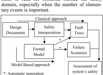
− Even if the formalism of fault trees allows an easy computation of qualitative and quantitative re-sults, this formalism is different from the repre-sentation of the system. The fault trees can be dif-ficult to read for someone outside the safety domain, especially when the number of elemen-tary events is important.
Figure 2 : The two approaches
We think these limits can be overcome by perform-ing the safety analysis activities on formal model of the system under development. Instead of building one fault tree for each failure condition, we provide a formal model describing both the nominal behav-iour and the dysfunctional behavbehav-iour of the system. On this model, several failure conditions can be studied. The failure scenarios as well as the FTA could be automatically generated.
4 ALTARICA
Amongst all the languages available in the literature to perform MBSA, we have chosen to use AltaRica, a formal modelling language, developed at LaBRI to describe both functional and dysfunctional behaviour of a system (Arnold et al. 2000). Moreover, the lan-guage is carried out by several tools. We use the tool Cecilia™ OCAS from Dassault Aviation to edit graphically the model then to analyse it by several means: simulation, automatic generation of minimal cuts (i.e. the shortest scenarios leading to the failure condition) or sequences (i.e. ordered cuts).
An AltaRica model is a network of intercon-nected components so called “nodes”. A node is atomic or composed of interconnected sub-nodes.
Each node has a finite number of:
- flow variables. They are the inputs and the outputs of the node used to link the node and its environment (other nodes).
- state variables. These internal variables memorize current or previous functioning mode (for example, failure mode). In our models, these variables (flow and state) be-long to finite domains of values (Boolean or enumerated)
- events. They label changes of the value of state variables. They model the occurrences of fault, human action or a reaction to a change of one input value.
The node dynamic is defined by:
- init. This is used to assign initial value to state variables
- transitions. They describe how the state vari-ables are modified. They have the following format: “G(s,v) |- E ->s_”where G(s,v) is a Boolean condition on state variables s and input variables v, E is the event and s_ is the effect of the transition on state variables. If the condition G is true, then the event E can be triggered and state variables are modified as described in s_.
- assertions. These equations describe how output variables are computed from inputs and state variables.
These concepts are illustrated by the following ex-ample.
node Pipe
//declaration of variables and events flow
input: bool: in; output: bool: out; state
ST = {ok, ko}; event Leakage;
//dynamic of the states init
ST:=ok; trans
ST=ok |- leakage -> ST:= ko; //function performed in each states assert
output = case { ST=ok : input, else false} ; edon
This component has one input and one output vari-ables both ranging over the Boolean domain {true, false}, one state variable ST ranging over the domain {ok, ko} and one event Leakage. At the initial in-stant, the node is in state “ok”. The event Leakage describes a failure which leads the node into the state “ko”. “Leakage” can be triggered only if the node is in state “ok”. The assertion means that the output Fault Trees Formal Model Failure Scenarios Assessment of system’s safety Design Documents Safety Interpretation Classical approach
Model Based approach *: Automatic generation
* *
value is equal to the input one if the node is in state “ok”. In other cases, the output value is “false”.
5 INFORMATION NEEDED TO BUILD
ALTARICA MODELS
This section aims at identifying the information needed to build a set of AltaRica nodes relevant for the safety assessment of a detailed system design. In (Humbert et al. 2008a), a process is proposed to identify the information useful to model computer based systems. We give here an overview of this ap-proach that was generalized to deal with multi-physics systems. Details will be given further for the application of the methodology to mechanical and hydro-mechanical domains.
5.1 Model purpose and requested preliminary analysis
The model perimeter shall fully cover the system under study and it shall enable the analysis of a set of failure conditions on this perimeter.
To reach this goal, the model shall focus on the fault propagation inside the studied perimeter. The faults are propagated between components that are functionally or physically dependant. The fault can be detected and tolerated by specific mechanisms that shall occur inside the model.
Finally, the failure condition shall be observable inside the model.
So before starting the modelling activity, three main kinds of data shall be specified:
− perimeter and structure of the system;
− expression of the failure conditions in relation-ship with the model perimeter;
− propagation laws inside each atomic components that results both from functions performed in the nominal case and from potential faults and ob-servable failure modes.
First, we propose to carry on the following prelimi-nary analysis steps:
− functional analysis of the system and the sub-systems;
− decomposition of the global system into sub-systems;
− identification of the interfaces between these sub-systems;
− identification of the system failure conditions and associated requirements;
− declination of system failure conditions (and their requirements) to sub-systems;
− in each sub-system, identification of components which have an impact on the failure conditions; − in each sub-system, identification of the interfaces
between these components;
− identification of potential component faults and failure modes.
Let us now clarify how the results of this preliminary analysis are used to specify the needed data.
5.2 Characterization of the model overall structure
When an AltaRica model is built to assess a detailed system design, the choice and the granularity of the AltaRica nodes used to cover the system perimeter depend first on pre-existing design choice. When the system was decomposed into sub-systems and com-ponents, the model structure will reflect as much as possible the predefined structure of the system. When the structure does not present any hierarchy, it is interesting to identify sub-systems made of groups of physically homogeneous components: as we will see in the next sections, the fault propagation inside components of a same physical domain can generally be achieved by a set of homogeneous physical pa-rameters.
This granularity can be refined accordingly to the functional analysis to make explicit functions inte-grated into organic components. In particular, fault detection, isolation and recovery mechanisms shall be identified and handled in some nodes.
Conversely, a set of organic or functional compo-nents may be removed or grouped into one equiva-lent node for sake of efficiency. This is particularly meaningful when the abstracted components do not impact the studied failure conditions. The soundness of such a choice can be justified either by the func-tional analysis or by the failure mode analysis. Then, for each identified nodes, the choice of input-output flows shall reflect physical or functional points of dependency between the node and its envi-ronment. It is worth noting that, if the concept of in-put/output oriented flows corresponds to a physical reality for computer based systems, it is less natural for electrical, hydro-mechanical or mechanic system. In these last cases, the functional analysis helps to identify the physical parameters handled by the nodes as we will see in section 7.
5.3 Characterization of observable failure condition
As written in section 5.1, the studied failure condi-tions shall be observable inside the model. For this purpose, we begin by expressing the global system failure condition in relationship with the model pe-rimeter (i.e. declining the system failure condition to the sub-system). Then, the choice of input-output flows and theirs granularities (i.e. their definition domains) shall allow the depiction and the observa-tion of these failure condiobserva-tions.
Practically and to perform this observation, spe-cial nodes (called observer) are defined in the Al-taRica model.
5.4 Characterization of an atomic node
Once the model overall structure and the failure condition to observe defined, we shall model the propagation laws in each identified node of the model. For this purpose, we first refined the high level input-output (I/O) flows (defined in section 5.2) into concrete flows. For it, we use 1) the func-tional analysis of the component, 2) the FMEA and 3) the failure conditions to observe (i.e. the objec-tives of the model). Although the choice of these flows remains highly subjective some recommenda-tions shall be made:
- choosing physical greatnesses to refined high level I/O flows allow the propagation of in-formation in the model;
- depending on the goal of the model, we can propagate by I/O flows the value of a great-ness (nominal, low,…) or its quality (correct / erroneous);
- I/O flows could be unidirectional or bidirec-tional (in several physical domains, a fault has consequences on components located both downward and upward).
Once the I/O concrete flows identified, we are inter-ested in the different events to take in account in the model. For it, we shall identify, for each component, the functions performed in the nominal case, its po-tential failure modes and the failure propagation in-side the component.
Practically, the functions performed in the nomi-nal case are identified thanks to the functionomi-nal anomi-naly- analy-sis and available design documents.
Concerning the potential failure modes to model, they are derived from both the functional analysis and the FMEA. The second one (used to describe the internal and organic failure modes of the component) is too detailed: for a given component, two different failure modes can lead to the same functional effect). So, the first one allows the identification of high level failure modes. Then, the AltaRica model will embed, as much as possible, these high level failure modes; each of these ones corresponding to one ore more organic failure mode described in the FMEA. From another point of view, if two (or more) events of the FMEA have the same effect on the compo-nent, we can model them as one unique AltaRica event (of course, the probability of this resulting event has to be computed from the probability of the two initial events).
Concerning the fault propagation inside the com-ponent, we have to identify a set of failure modes which can be propagated to the input of the compo-nent.
The previous steps allow the identification of I/O flows and events to propagate by and through the components. Now, we shall identify the definition domain of these I/O flows. According to us, an ade-quate solution is to choose these definition domains in order to model the necessary and sufficient infor-mation to both propagate the identified events and observe the considered failure conditions.
At this stage, we have defined the static parts of the node, i.e. the flow and state variables, the events. Here, we want to define the dynamic of the AltaRica node, i.e. the transitions. To achieve this goal, two main kinds of data shall be specified.
The first one is the trigger mechanism of each identi-fied events, i.e. the condition under which an event can be triggered (for example, an event can be trig-ger only if the component is in a specific state). On AltaRica model, this step leads to the definition of the transition guards and allow, among other things, to model faults in domino effect.
Secondly, for each identified event, we have to identify if this event is permanent or transient (for example, to model transient failure). In case of tran-sient event, we add to the model a “reverse event” and a transient state. The associated transitions will be described such as
// Transitions associated with transient event ST=ok |- Transient_event -> ST:= transient; // Transitions associated with reverse event ST:= transient |- Reverse_event -> ST:=ok;
We have now to model the AltaRica assertions. Such assertions will be defined as decision tables: each output is defined depending on the value of the state variables (the current state of the node) and the value of the input flow variables.
-
Thus, this methodology aims at abstracting system-atically details of physics so that the formal safety models provide information at meaningful granular-ity level for safety experts. The following sections aim at applying the methodology for the case study. In this purpose, the section 6 develops the prelimi-nary analysis of the global system. Then, the method is applied to mechanical system in section 7. Results for hydro-mechanical and computer-based systems are described in section 8 and 9.
6 PRELIMINARY ANALYSIS OF THE CASE
STUDY
6.1 Model overall structure
According to Figure 1, the global system can be de-composed into three systems of interest:
− A mechanical system: the mechanical transmis-sion from turbines to the helicopter rotor;
− A hydro-mechanical system: the fuel circuit of the engine;
− A control system which adapts the engine to the helicopter power requirements whilst remaining within defined limits.
About the interfaces between these three sub-systems, they are depicted on Figure 1:
− The mechanical system speed measure is trans-mitted to the control system by sensors;
− The control system transmits to the fuel circuit 1) the fuel quantity setting, 2) the command for the fuel shut off valve;
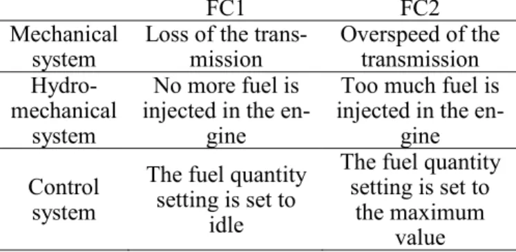
− The fuel circuit transmits the fuel to the combus-tion chamber (i.e. to the mechanical system). 6.2 Declining failure conditions to sub-systems Let us remind that studied high level failure condi-tions are 1) the In Flight Shut Down (IFSD) of the engine and 2) an overspeed of the engine. In the fol-lowing table, we call them FC1 and FC2 and we de-cline them to the three sub-systems of interest. Table 1. Failure conditions declined to sub-systems
FC1 FC2
Mechanical system
Loss of the trans-mission Overspeed of the transmission Hydro-mechanical system No more fuel is injected in the
en-gine
Too much fuel is injected in the
en-gine Control
system
The fuel quantity setting is set to
idle
The fuel quantity setting is set to
the maximum value
7 APPLICATION TO MECHANICAL SYSTEM
7.1 Preliminary analysis: architecture of the mechanical sub-system
To identify the components which have an impact on the considered failure conditions, we use the failure analysis (the FMEA). Thus, components with an im-pact of the studied failure conditions will be mod-elled; components without impact on considered failure conditions will not be modelled; components without effect on the safety of the system will not be modelled.
We identify the architecture of the mechanical sub-system. Without details, this system is typically composed by mechanical gears, bearings, shafts, screws…
Then, we use the design documents to identify the functional interfaces between the different
compo-nents. Thus, we construct a first architecture of the sub-system.
From this point, we suppose that 1) we have a list of components to model and 2) we know the objectives of the model, i.e. the list of failure conditions to ob-serve on the model (Cf. Table 1).
In this section, we consider the example of a me-chanical shaft. This shaft is a simple rotating shaft which transmits power from an input point to an output point.
7.2 High level input-output flows
To identify high level input-output (I/O) flows, we perform a functional analysis (Figure 3) of the com-ponent (the shaft). In this analysis, we identify all functional inputs and outputs, i.e. all functional in-terfaces between the component and its environment.
Figure 3 : Functional analysis of the shaft
These high level I/O flows are refined in the further steps of the method. In the paper, we are mainly in-terested in the input and output power.
7.3 Characterization of the behaviour
In this section, we identify 1) the AltaRica events; 2) the AltaRica transitions; 3) the level of details of I/O flows variables.
As already explained in section 5.4, events (func-tional and dysfunc(func-tional) are identified from the functional analysis and from the FMEA. Without de-tails, the considered events are here the breakdown of the shaft and the emission of metallic particles.
Once these events identified, we can picture the functional and dysfunctional states of the compo-nent. Here, there is one functional state (transmis-sion ok and no emis(transmis-sion of particles) and three dys-functional states ({transmission ko, no particles}; {transmission ok, particles emitted}; {transmission ko, particles emitted}).
By combining the events and these states, we can describe the transitions between these states.
To refine the high level I/O flows (input and output power), we are interested in fault propagations in the model. The model of the shaft shall propagate both its own events (breakdown) and the event of its envi-ronment (other components). For it, we identify pos-sible events in the system which can have an effect on the input of the component. Here, we identify one event: a breakdown of the transmission between the
Oil
Input power Output power
Used oil Guidance
Transmitting the power
engine and the helicopter. Considering the FMEA, the described failures have effects on 1) the torque transmitted and 2) the rotation speed of the mechani-cal component. A failure can affect the torque, the speed or the two. So, we choose to propagate the couple {torque, speed}.
Moreover and because a mechanical system is a continuous system, a fault of the shaft has conse-quences on components located downward and also upward. So, the propagation of the couple {torque, speed} has to be bidirectional.
Figure 4 : Input / output variables for the propagation of fail-ures in a mechanical sub-system
About the “Oil” and “Used Oil”, we propagate in the mechanical model two variables: 1) the presence or the absence of oil and 2) the presence or the absence of particles in the oil. Both of these variables are Booleans. The propagation is unidirectional (up-stream to down(up-stream).
About the guidance of the shaft, we propagate the correct realization (or not) of the function. So, the guidance is modelled with a unique Boolean vari-able. The propagation is unidirectional (upstream to downstream).
Now, we have to identify the level of details of these variables. About this level of details and according to us, an adequate solution is to propagate the neces-sary and sufficient information to achieve the objec-tives of the model. Here, the failure modes to propa-gate are breakdowns. Also, we have to propapropa-gate the overspeed in the system. So, because we want here observe the loss and the overspeed of the transmis-sion, we choose as level of detail:
− {ok, null, too high} for the torque variable; − {ok, null, overspeed} for the speed variable. Table 2. Modelling of a breakdown
Outputs Value
Torque to upstream Null
Speed to upstream Null
Torque to downstream Null
Speed to downstream Null
8 RESULTS FOR HYDRO-MECHANICAL
SYSTEM
In this section, we present the crucial information about the modelling of a hydro-mechanical system. Architecture of hydro-mechanical system. Typically, such a system is composed with several pumps
(move fluid and create pressure), filters (protect sys-tem by retaining particles), valves (supply fluid un-der conditions) or pipes (supply fluid).
Events. Typically, events are leakage or clogging of the component. Several level of severity could be considered for these events.
I/O flows. To propagate these events and observing the failure conditions (section 6.2), we propagate the couple {fluid flow, fluid pressure} in the model. The propagation is bidirectional. For these variables, we choose as level of detail:
− {ok, no, too high} for the fluid flow variable; − {ok, no, overpressure} for the fluid pressure
vari-able.
Other variables are also considered such as the temperature of the fuel (Boolean: normal or too hot), the presence of particles in the fuel (Boolean), the behaviour of the flow (Enumerated: normal, stucked constant, oscillation). All of these variables are uni-directional (propagated to downstream components).
9 SOFTWARE MODELLING
In this section, we present the crucial information about the modelling of a computer based system. Architecture of computer based system. A computer based system relates to the digital components of a system.
Events. (Bieber et al. 2004) define three essential failure modes: loss, untimely delivery and erroneous operation of function.
I/O flows. This kind of system differs in several ways from other physical systems already intro-duced. If the thread of the method remains constant, the study is stopped to the functional level and propagation information are generally limited to the quality of the realized functions. Moreover, digital components have well identified inputs and outputs. Thus, a failure of a component will have direct con-sequences only on components which use specifi-cally the result of the function. Thus, we only have to propagate the failure (i.e. if the signal is reliable, erroneous or lost) to other components which are functionally downstream the component under study.
10 CONCLUSION
This paper presents research works that has been car-ried out in the aeronautic field to enhance the safety assessment of physical systems. A common method-ology can be used to help the formalization of the failure propagation inside systems made of various Torque from upstream
Speed from upstream Torque to upstream Speed to upstream
Torque to downstream Speed to downstream Torque from downstream Speed from downstream
technologies (mechanical, hydro-mechanical or computer-based systems). The methodology aims at abstracting systematically details of physics so that the formal safety models provide information at meaningful granularity level for safety experts. Moreover, they enable tackling significant systems, without loosing completeness and soundness, with respect to the results provided by equivalent tradi-tional safety analysis.
Thus, this paper presents the application of the methodology for the AltaRica modelling of me-chanical, hydro-mechanical and computer-based sys-tems. Today, AltaRica approach becomes more and more operationally used in industry (For example, Dassault, Airbus, Turbomeca) and it highlights an-other domain dependant successful use of formal methods. Nevertheless, some languages limits de-serve to be considered. The observations of failure conditions and the propagation of failures need some modelling artefacts. For instance, bidirectional propagation is achieved by decomposing component interfaces into two variables: one input variable and one output variable. Also, it could be quite difficult to model interfaces without physical links between two components. In a more general way, it is diffi-cult to model components where inputs and outputs are not well identified. The proposed methodology leads to tractable and accurate models. However, the model is not easy to validate.
To follow this direction, further works deal cur-rently with ways to integrate more and more rigor-ously these formal models in the overall safety and design process. For instance, we are studying how to validate systematically a new library or a given model before using it for safety assessment.
Another issue is more related to system engineer-ing practices. Indeed, it may be hard to find a speci-fication of the system behaviour at a good abstrac-tion level. Accurate details can often be found in design documents but these details need to be ab-stracted for the safety analysis purpose. We believe that the modelling task is easier if system formal specifications already exist. So, our work is on-going to define a formal specification of the system. This specification will be beginning of the AltaRica mod-elling and a support for the validation of the model.
REFERENCE
Arnold, A., Griffault, A., Point, G., Rauzy, A.. 2000. The Al-taRica Formalism for Describing Concurrent Systems. In Fundamenta Informaticae, vol. 40, n°2-3, pp. 109--124, IOS Press (2000)
SAE. 1996. ARP4754: Certification considerations for highly integrated or complex aircraft systems. Society of Automo-tive Engineers. SAE international, Aerospace Recom-mended Practice.
SAE. 1996. ARP4761: Guidelines and Methods for Conducting the Safety Assessment Process on Civil Airborne Systems
and Equipment. SAE international, Aerospace Recom-mended Practice.
Bieber, P., Bougnol, C., Castel, C., Heckmann, J.-P., Kehren, C., Metge, S., Seguin, C. 2004. Safety Assessment with Al-taRica - Lessons learnt based on two aircraft system studies. In 18th IFIP World Computer Congress, Topical Day on New Methods for Avionics Certification, August 26th, 2004, Toulouse (France), LNCS series(copyright Springer-Verlag): 505-510
Bieber, P., Blanquart, J.-P., Durrieu, G., Lesens, D., Lucotte, J., Tardy, F., Turin, M., Seguin, C., Conquet, E. 2008. Integra-tion of formal fault analysis in ASSERT: Case studies and lessons learnt. In: ERTS 2008, Toulouse.
Bouissou, M., Bouhadana, H., Bannelier, M., Villatte, N. 1991. Knowledge modelling and reliability processing: presenta-tion of the FIGARO language and associated tools. In Lin-deberg, J.F. (ed.), SAFECOMP'91, IFAC Symposia, Trondheim, series #8, pp. 69--75, Pergamon Press (1991) Bozzano, M., Villafiorita, A., Åkerlund, O., Bieber, P.,
Bougnol, C., Böde, E., Bretschneider, M., Cavallo, A., Cas-tel, C., Cifaldi, M., Cimatti, A., Griffault, A., Kehren, C., Lawrence, B., Lüdtke, A., Metge, S., Papadopoulos, C., Passarello, R., Peikenkamp, T., Persson, P., Seguin, C., Trotta, L., Valacca, L., Zacco, G. 2003. ESACS: an inte-grated methodology for design and safety analysis of com-plex systems, in proceedings of ESREL 2003,Balkema pub-lisher
Joshi, A., Whalen, M., Heimdahl, M. 2006. Model-based safety analysis final report. NASA contractor report, NASA/CR-2006-213953.
Humbert, S., Castel, C., Seguin, C., Dutuit, Y., Bosc, J.M., Darfeuil, P.. 2006. Méthodologie de modélisation AltaRica pour la Sûreté de Fonctionnement d’un système de propul-sion d’un hélicoptère incluant une partie logicielle. Lambda Mu 15,9-13 octobre 2006, Lille (France)
Humbert, S., Seguin, C., Castel, C., Bosc, J-M. 2008a. Deriv-ing Safety Software Requirements from an AltaRica System Model. In: SAFECOMP08, Michael D. Harrison and Mark-Alexander Sujan.
Papadopoulos, Y. & Maruhn, M.: Model-based automated syn-thesis of fault trees from Matlab-Simulink models. In DSN'01, International Conference on Dependable Systems and Networks (former FTCS), Gothenburg, pp.77--82, ISBN 0-7695-1101-5 (2001)
Villemeur, A. Reliability Availability Maintainability and Safety Assessment, John Wiley & Sons Ltd, 1992.