Pépite | Contribution à l’étude du piquage pour renforcement des composites
136
0
0
Texte intégral
(2) Thèse de Lingshan Liu, Lille 1, 2017. © 2017 Tous droits réservés.. lilliad.univ-lille.fr.
(3) Thèse de Lingshan Liu, Lille 1, 2017. ACKNOWLEDGEMENTS Firstly, I would like to express my sincere gratitude to my project directors: Prof. Damien SOULAT, Dr. Xavier LEGRAND and Dr. Peng WANG, for the continuous support of my Ph.D study and related research, for their patience, motivation, and immense knowledge. Their consistent concern and valuable guidance has helped me in all the time of research and writing of this thesis. All of my Ph.D supervisors have remained kind throughout and favoured me a lot. I am very much thankful to my predecessors of the same research group: Jean-Vincent RISICATO and Ahmed Rashed LABANIEH for their assistance during my research work. Thanks to my research contemporary friends Boris DUCHAMP, Fatma OMRANI, Tao ZHANG and Chang LIU for technical discussions and knowledge-sharing during my time spent for Ph.D thesis. Especially heartfelt thanks to my best friend Fatma for her encouragement and company during the last four years. From the first day of Ph.D life, we have seen and helped each other through both good times and bad. I will always remember the great conversations we had over lunch, and I know that we will break bread together many more times. I am also indebted to my fiancé Ye LV, for his enduring love, for believing in me long after I’d lost belief in myself, and for sharing my wish to reach the goal of completing this task, but caring enough to love me even if I never achieved it. Last but not the least, I would like to thank my parents Xiangyu LIU and Qiuhong HUANG, for giving birth to me at the first place and supporting me spiritually throughout my life.. i. © 2017 Tous droits réservés.. lilliad.univ-lille.fr.
(4) Thèse de Lingshan Liu, Lille 1, 2017. ii. © 2017 Tous droits réservés.. lilliad.univ-lille.fr.
(5) Thèse de Lingshan Liu, Lille 1, 2017. CONTENTS GENERAL INTRODUCTION .......................................................................................... 1 PROBLEM STATEMENT ........................................................................................................ 1 THESIS OVERVIEW .............................................................................................................. 3 REFERENCE OF GENERAL INTRODUCTION ........................................................................... 3 1 STATE OF THE ART ...................................................................................................... 7 1.1 INTRODUCTION ............................................................................................................. 7 1.1.1 The composite materials ....................................................................................... 7 1.1.2 Composition of composite materials .................................................................. 11 1.1.3 The process of composite manufacturing ........................................................... 14 1.1.4 Textile preforms ................................................................................................. 18 1.2 LAMINATE FIBRE REINFORCED COMPOSITES ............................................................... 19 1.3 THE 3D REINFORCEMENTS .......................................................................................... 23 1.3.1 Woven fibre reinforced composites .................................................................... 24 1.3.2 Knitted composites ............................................................................................. 25 1.3.3 Braided composites ............................................................................................ 26 1.3.4 Stitched composites ............................................................................................ 28 1.3.5 Z pinned composites ........................................................................................... 30 1.3.6 Tufted composites .............................................................................................. 30 1.4 CONCLUSION OF CHAPTER 1........................................................................................ 32 REFERENCE OF CHAPTER 1 ................................................................................................ 33 2 TUFTING PROCEDURE: A METHOD TO MANUFACTURE OR ASSEMBLE THROUGH-THICKNESS REINFORCEMENTS ........................................................ 40 2.1 INTRODUCTION ........................................................................................................... 40 2.1.1 Introduction of stitching process ........................................................................ 41 2.1.2 Introduction of tufting technology...................................................................... 44 2.2 PARAMETERS OF TUFTING PROCESS ............................................................................ 44 2.2.1 Tufting density.................................................................................................... 45 2.2.2 Tuft length .......................................................................................................... 46 2.2.3 Other parameters ................................................................................................ 46 iii. © 2017 Tous droits réservés.. lilliad.univ-lille.fr.
(6) Thèse de Lingshan Liu, Lille 1, 2017. 2.3 TUFTING MACHINE...................................................................................................... 48 2.3.1 Functions of the machine ................................................................................... 48 2.3.2 Designing of the machine ................................................................................... 49 2.3.3 Assemblage of the machine................................................................................ 59 2.3.4 Operating instructions of the machine ............................................................... 60 2.4 CHARACTERIZATION OF TUFTING YARN ...................................................................... 67 2.5 CONCLUSION OF CHAPTER 2 ....................................................................................... 69 REFERENCE OF CHAPTER 2 ............................................................................................... 70 3 INFLUENCE OF TUFT LENGTH THROUGH THE THICKNESS ON MECHANICAL PROPERTIES OF TUFTED COMPOSITES ................................... 72 3.1 INTRODUCTION ........................................................................................................... 72 3.2 MATERIAL AND METHOD ............................................................................................ 73 3.3 CHARACTERISATION OF THE TUFTED PREFORM AND COMPOSITE ................................ 76 3.3.1 Preparation of the tufted composite sample ....................................................... 76 3.3.2 Effective Tuft Length (ETL) .............................................................................. 78 3.3.3 Micro-observation .............................................................................................. 81 3.4 TENSILE RESULTS ....................................................................................................... 82 3.5 DISCUSSION ................................................................................................................ 86 3.6 CONCLUSION OF CHAPTER 3 ....................................................................................... 88 REFERENCES OF CHAPTER 3 ............................................................................................. 88 4 INFLUENCE OF THE TUFTING YARNS ON FORMABILITY OF TUFTED 3D COMPOSITE REINFORCEMENT ............................................................................... 92 4.1 INTRODUCTION ........................................................................................................... 92 4.2 MATERIAL AND METHOD ............................................................................................ 96 4.2.1 Tufting process and tufted 3D composite reinforcement ................................... 96 4.2.2 Hemispherical preforming.................................................................................. 98 4.3 FORMING RESULTS.................................................................................................... 100 4.3.1 The single layer and multilayered reinforcement forming ............................... 100 4.3.2 The tufted 3D reinforcement forming .............................................................. 103 4.4 ANALYSIS AND DISCUSSION ABOUT THE INFLUENCE OF TUFTING YARNS .................. 106 4.4.1 Influence on the material draw-in .................................................................... 106 4.4.2 Influence on the inter-layer sliding .................................................................. 107 4.4.3 Influence on the punch force ............................................................................ 108 iv. © 2017 Tous droits réservés.. lilliad.univ-lille.fr.
(7) Thèse de Lingshan Liu, Lille 1, 2017. 4.4.4 Influence on the forming defects ...................................................................... 109 4.4.5 Influence of tufting yarn orientations ............................................................... 110 4.5 CONCLUSION OF CHAPTER 4 ..................................................................................... 112 REFERENCE OF CHAPTER 4 ............................................................................................. 113 5 GENERAL CONCLUSION ........................................................................................ 120 5.1 CONCLUSION ............................................................................................................ 120 5.2 PERSPECTIVE ............................................................................................................ 122 ABSTRACT AND RÉSUMÉ.......................................................................................... 124. v. © 2017 Tous droits réservés.. lilliad.univ-lille.fr.
(8) Thèse de Lingshan Liu, Lille 1, 2017. LIST OF TABLES TABLE 1-1 COMPARISON. OF CHARACTERISTICS BETWEEN COMPOSITE MATERIALS AND. METALS ........................................................................................................................ 10. TABLE 1-2 MAIN CHARACTERISTICS OF MOST USED THERMOSETTING RESINS ...................... 12 TABLE 1-3 TYPICAL PROPERTIES OF SOME REINFORCEMENT ................................................ 14 TABLE 2-1 MAIN PARAMETERS OF TUFTING EQUIPMENT. ..................................................... 60 TABLE 2-2 PROPERTIES OF TORAYCA® FT300 ................................................................. 67 TABLE 2-3 PROPERTIES OF 67×2TEX TENAX® CARBON THREAD ....................................... 68 TABLE 3-1 TUFTING CARBON THREAD PROPERTIES. ............................................................. 75 TABLE 3-2 MAIN PROPERTIES OF THE TUFTED PREFORM AND COMPOSITE ............................ 78 TABLE 3-3 MEASUREMENT OF TUFT LENGTHS. ..................................................................... 81 TABLE 3-4 CHARACTERISATION. OF TENSILE SAMPLES AFTER BREAK (PARTIALLY INSERTED. TUFT). ........................................................................................................................... 84. TABLE 3-5 CHARACTERISATION OF TENSILE SAMPLES AFTER BREAK (FULLY INSERTED TUFT). ..................................................................................................................................... 86 TABLE 4-1 MAIN PROPERTIES OF THE TUFTED 3D FABRIC SPECIMENS. ................................. 98 TABLE 4-2 THE MAIN PARAMETERS OF THE HEMISPHERICAL PREFORMING......................... 100 TABLE 4-3 INFLUENCE. OF TUFTING YARNS ORIENTATION IN THE FORMING OF TUFTED. 3D. PREFORMS. ................................................................................................................. 111. vi. © 2017 Tous droits réservés.. lilliad.univ-lille.fr.
(9) Thèse de Lingshan Liu, Lille 1, 2017. LIST OF FIGURES FIGURE 1-1 APPLICATIONS OF COMPOSITE MATERIALS ........................................................... 8 FIGURE 1-2 RESIN TRANSFER MOULDING INJECTION PROCESS ............................................. 15 FIGURE 1-3 PRINCIPLE OF RFI PROCESS. .............................................................................. 16 FIGURE 1-4 PRINCIPLE OF LRI PROCESS. .............................................................................. 17 FIGURE 1-5 DIFFERENT. FORMS OF REINFORCEMENT: (A). UD. SHEET, (B) MAT, (C) WOVEN. FABRIC, (D) THREE-DIMENSIONAL ORTHOGONAL WOVEN FABRIC ................................. 18. FIGURE 1-6 LAMINATE MADE BY STACKING LAMINAS IN DIFFERENT ORIENTATION. ............. 20 FIGURE 1-7 LAMINA. FIBRE REINFORCED COMPOSITE: (A) LAMINA WITH UNIDIRECTIONAL. FIBRE; (B) LAMINA WITH 2D WOVEN FABRIC.. FIGURE 1-8 SPECIFIC. ............................................................... 20. STRENGTH IN FUNCTION OF SPECIFIC MODULUS OF FIBRE, LAMINA,. LAMINATE AND METALS.. FIGURE 1-9 COMPARISON. .............................................................................................. 22. OF THE IN-PLANE TENSILE MODULUS, TENSILE STRENGTH AND. COMPRESSIVE STRENGTH TO THAT IN THE THROUGH THICKNESS PROPERTIES FOR LAMINATE COMPOSITE MATERIALS. .............................................................................. 23. FIGURE 1-10 DEGRADATION OF THE IN-PLANE TENSILE AND COMPRESSIVE STRENGTH AFTER IMPACT NORMALIZED TO THE STRENGTH BEFORE IMPACT IN FUNCTION OF THE IMPACT ENERGY. ....................................................................................................................... 23. FIGURE 1-11 TYPICAL 3D WOVEN ARCHITECTURES: (A) LAYER-TO-LAYER ANGLE INTERLOCK; (B) THROUGH-THICKNESS ANGLE INTERLOCK; (C) ORTHOGONAL.................................. 25 FIGURE 1-12 (A) SHEMATIC. OF WEFT KNITTED FABRIC; (B) SHEMATIC OF WARP KNITTED. FABRIC .......................................................................................................................... 26. FIGURE 1-13 (A) OVERALL VIEW OF A BRAIDING MACHINE (GEMTEX). (B) DESCRIPTION OF THE MAIN ELEMENTS OF A BRAIDING PROCESS. ............................................................. 27. FIGURE 1-14 (A) OUTLINE. OF THE CARRIERS ON A. 3D. BRAIDING MACHINE; (B) DETAILED. VIEW OF THE MOTION OF A HORN-GEAR DURING A 3D BRAIDING OPERATION. .............. 27. vii. © 2017 Tous droits réservés.. lilliad.univ-lille.fr.
(10) Thèse de Lingshan Liu, Lille 1, 2017. FIGURE 1-15 STITCHED. COMPOSITE: STACKED. 2D. LAMINAS SEWED WITH MODIFIED LOCK. STITCH. ......................................................................................................................... 29. FIGURE 1-16 SCHEMATIC OF THE Z-PINNING PROCESS OF LAMINATE COMPOSITE. ............... 30 FIGURE 1-17 SCHEMATICS. OF. (A). STITCHING AND. (B). TUFTING PROCESS APPLIED TO. SANDWICH PANELS. ...................................................................................................... 31. FIGURE 2-1 SCHEMA OF CONVENTIONAL LOCK STITCH (A) AND MODIFIED LOCK STITCH (B). ..................................................................................................................................... 41 FIGURE 2-2 SCHEMA OF CHAIN STITCH. ................................................................................ 42 FIGURE 2-3 ONE-SIDE STITCHING NEEDLE (A) AND SCHEMA OF OSS® TECHNOLOGY (B). [3] 43 FIGURE 2-4 TUFTING TECHNOLOGY: AEROTISS® 03S. ......................................................... 43 FIGURE 2-5 PARAMETERS OF TUFTING PROCESS. .................................................................. 45 FIGURE 2-6 SCHEMATIC OF THE THREAD ARRANGEMENT IN A TUFTED PREFORM. ................ 46 FIGURE 2-7 SCHEMATIC OF TUFTING ANGLE. ........................................................................ 47 FIGURE 2-8 TUFTING NEEDLES WITH INCLINED HOLE (A) AND HOLLOW NEEDLE (B)............. 48 FIGURE 2-9 DESIGN DRAWING OF TUFTING EQUIPMENT IN SOLIDWORKS. ............................ 50 FIGURE 2-10 PNEUMATIC CYLINDER AND NEEDLE................................................................ 51 FIGURE 2-11 FRAME PIECE FOR CHANGING HEIGHT AND THE BRAKE. ................................... 52 FIGURE 2-12 ESTIMATING OF TUFT LENGTH. ........................................................................ 53 FIGURE 2-13 PLASTIC BOBBIN SUPPORT. .............................................................................. 54 FIGURE 2-14 CALCULATION OF RESERVED DISTANCE OF TUFTING THREAD. ......................... 55 FIGURE 2-15 FEEDING SYSTEM. ............................................................................................ 56 FIGURE 2-16 PRESSER FOOT SYSTEM.. .................................................................................. 57 FIGURE 2-17 ROUND PRESSER FOOT (A); UNI-DIRECTIONAL PRESSER FOOT (B). ................... 58 FIGURE 2-18 THE FRAME (A) AND THE FOAM (B). ................................................................. 58 FIGURE 2-19 THE FRAME WITH GUIDING RAILS. ................................................................... 59 FIGURE 2-20 ASSEMBLAGE OF TUFTING MACHINE. ............................................................... 60. viii. © 2017 Tous droits réservés.. lilliad.univ-lille.fr.
(11) Thèse de Lingshan Liu, Lille 1, 2017. FIGURE 2-21 MANUAL OPERATING CONSOLE OF TUFTING MACHINE. .................................... 61 FIGURE 2-22 PATH OF THREADING TUFTING YARN. .............................................................. 62 FIGURE 2-23 TUFTING PROCESS. ........................................................................................... 63 FIGURE 2-24 HOME SCREEN OF THE PCDUINO. .................................................................... 64 FIGURE 2-25 LAUNCH THE INTERFACE. ................................................................................ 64 FIGURE 2-26 THE INTERFACE OF AUTOMATICALLY CONTROLLING SYSTEM. ......................... 65 FIGURE 2-27 INTERFACE FOR CONTROLLING MOTOR OF X AXIS. .......................................... 66 FIGURE 2-28 TORAYCA® FT300 CARBON FIBRE AND TWISTED THREAD. .......................... 68 FIGURE 3-1 THE LAMINATE OF THE PREFORM AND THE POSITION OF RELEASE FILM. ............ 74 FIGURE 3-2 DRY TUFTED PREFORM WITH A TUFTING DENSITY OF 5MM. ............................... 75 FIGURE 3-3 THE PRINCIPAL OF LRI. ..................................................................................... 76 FIGURE 3-4 THE TUFTED PREFORM SAMPLE UNDER VACUUM INFUSION SYSTEM. ................. 77 FIGURE 3-5 THE TUFTED COMPOSITE SAMPLES. .................................................................... 78 FIGURE 3-6 DEFINITION OF RTL AND ETL. .......................................................................... 79 FIGURE 3-7 RTL AND ETL PRESENTED ON A TUFTED COMPOSITE SAMPLE. .......................... 79 FIGURE 3-8 MEASUREMENT OF THE ETL (E.G. FOR A SAMPLE WITH 24.6 MM DTL). ............ 80 FIGURE 3-9 CROSS SECTION OF TUFTED COMPOSITE SAMPLE UNDER MICRO-OBSERVATION. 82 FIGURE 3-10 (A) TENSILE INSTRUMENT AND (B) TENSILE TEST SET-UP. ................................ 83 FIGURE 3-11 BROKEN SURFACE OF TENSILE TEST SAMPLE. ................................................... 83 FIGURE 3-12 INFLUENCE. OF. ETL. ON MAXIMUM TENSILE LOAD PER TUFTING THREAD FOR. PARTIALLY INSERTED TUFT CASE. ................................................................................. 85. FIGURE 3-13 MICRO-OBSERVATION OF THE TUFTING THREADS IN TUFTED COMPOSITE IN THE CASE OF FULLY INSERTED TUFT. ................................................................................... 87. FIGURE 4-1 THE SEQUENCE OF TESTED PREFORM. ................................................................ 97 FIGURE 4-2 THE TOP VIEW OF TUFTING PATTERN. ................................................................. 97. ix. © 2017 Tous droits réservés.. lilliad.univ-lille.fr.
(12) Thèse de Lingshan Liu, Lille 1, 2017. FIGURE 4-3 TOP. VIEW (A) AND BOTTOM VIEW (B) OF TUFTED SAMPLE WITH A TUFTING. SPACING OF 10MM. ....................................................................................................... 98. FIGURE 4-4 THE HEMISPHERICAL PREFORMING DEVICE. ....................................................... 99 FIGURE 4-5 THE DIMENSIONS OF THE HEMISPHERICAL PREFORMING DEVICE...................... 100 FIGURE 4-6 DEFORMED PREFORM [0°/90°]4. AFTER HEMISPHERICAL STAMPING. ................ 101. FIGURE 4-7 DEFORMED PREFORM: [-45°/+45°]4 AFTER HEMISPHERICAL STAMPING. .......... 101 FIGURE 4-8 THE. MAXIMUM PUNCH FORCE OF SINGLE AND MULTILAYERED. E-GLASS. PLAN. WEAVES FORMING. ..................................................................................................... 102. FIGURE 4-9 THE MAXIMUM DRAW-IN OF SINGLE AND MULTILAYERED E-GLASS PLAN WEAVES FORMING. ................................................................................................................... 103. FIGURE 4-10 NON-TUFTED PREFORM AFTER PERFORMING.................................................. 104 FIGURE 4-11 3D PREFORM AFTER PERFORMING WITH TUFTING SPACING OF 20MM............. 104 FIGURE 4-12 3D PREFORM AFTER PERFORMING WITH TUFTING SPACING OF 10MM............. 105 FIGURE 4-13 3D PREFORM AFTER PERFORMING WITH TUFTING SPACING OF 5MM............... 105 FIGURE 4-14 INFLUENCE OF TUFTING DENSITY ON THE MATERIAL DRAW-IN. ..................... 106 FIGURE 4-15 INFLUENCE OF TUFTING DENSITY ON THE INTER-LAYER SLIDING. .................. 108 FIGURE 4-16 INFLUENCE OF TUFTING DENSITY ON THE PUNCH FORCE. ............................... 109 FIGURE 4-17 WRINKLING PHENOMENA IN THE FORMING OF (A) NON-TUFTED, (B) TUFTED 1.0 AND (C) TUFTED 0.5 PREFORMS. ................................................................................. 110. FIGURE 4-18 HEMISPHERICAL FORMING OF TUFTED 3D PREFORMS [0°/90°]2. ................... 111 FIGURE 4-19 HEMISPHERICAL FORMING OF TUFTED 3D PREFORMS [-45°/45°]2. ................ 112. x. © 2017 Tous droits réservés.. lilliad.univ-lille.fr.
(13) Thèse de Lingshan Liu, Lille 1, 2017. GENERAL INTRODUCTION Problem statement Laminated composites are wildly used in many industrial fields such as transport, construction, energy and defense. Comparing with metal materials, laminated composite presents better mechanical performances such as high specific strength and stiffness, highspecific energy absorption, and excellent fatigue performance. Laminated structures are constituted by laying up different laminas (unidirectional ply or 2D woven ply) in different orientations. However, the laminations of two-dimensional layered fibre structure show limitations including high cost and some inferior mechanical properties such as impact resistance and poor delamination resistance. [1, 2]. . Therefore, a large number of works are. conducted on the development of 3D preforms with reinforcements of high in plane densities, and including also the insertion of binding fibres to connect layers thereby combining excellent mechanical properties of layers to improve the resistance to delamination and impact resistance. [3, 4]. . Different approaches of manufacturing 3D. preforms are brought out and classified according to through-the-thickness reinforcement (TTR) methods [5, 6]. Thick or multilayered weaving and other specific technologies such as stitching, z-pinning and tufting are applied on insertion of through thickness fibrous structure in order to obtain 3D preforms. Tufting emerges as a popular method of localized Through-Thickness Reinforcement (TTR) for dry preforms. The tufting process involves inserting a single threaded needle through a preform, where friction within the preform is responsible for holding the thread in place as 1. © 2017 Tous droits réservés.. lilliad.univ-lille.fr.
(14) Thèse de Lingshan Liu, Lille 1, 2017. General introduction. the needle is retracted [7]. Tufting can be used to reinforce different types of textiles such as woven fabric, braided fabric or non-crimped fabric (NCF) layers. It requires only one side access of thread and does not require the use of second thread which makes it simpler and cost economic. Tufting thread is held by fabric itself with low tension which results in a reduction of the stitching effect on the in-plane properties and the possibility of manufacturing complex and large composite structures. This technology is still under development and few works have been realized to characterize the geometry and the mechanical performance of produced preform. Recently Hartley [8] et al. show that, with an experimental study that increasing the number of tufts (less than 3 tufts) within a sample did significantly increase the crushing performance by as much as 25 %, when compared to the untufted coupons. Colin de Verdiere et al.. [9]. investigate the effect of tufting on the. in-plane and out-of-plane mechanical response of NCF. They show that tufting increases considerably delamination resistance in mode I but to a lesser extent in mode II. However, in these studies the influence of the specific parameters of the binder reinforcement on the mechanical performance is less demonstrated. It is important to investigate and control tufting parameters for optimizing the process of tufting and mechanical performances of tufted composite. In order to produce 3D composite parts from 3D preforms, the first step is to understand the deformability of preform on more and more complex shapes (given by punch and die). Some experimental works on the 3D woven interlock. [10, 11]. and numerical works. [12, 13]. on. the development of specific behavior laws for the preforming simulation are brought out. The deformability of NCF (Non Crimp Fabrics), the fabric reinforced through thickness by stitching, during the preforming is well presented. [14-17]. . On the contrary, in these studies. the influence of the specific parameters of the binder reinforcement (density of stitching, orientation relatively to the punch, stitching yarns direction, etc...) on measurement criteria during the preforming is not demonstrated. Moreover, the influence of through-thickness fibres on the preforming defects is not described. The literature on preforming of dry 3D tufting preforms is null. Research works are needed to improve the understanding of formability of the tufted 3D fabric during manufacturing.. 2. © 2017 Tous droits réservés.. lilliad.univ-lille.fr.
(15) Thèse de Lingshan Liu, Lille 1, 2017. General introduction. Thesis overview This study is dedicated to the development of tufting technology and the analysis of the influence of tufting parameters on preforming behaviours and mechanical properties of tufted preform and composite. The chapter 1 is a review of the fibre reinforced composite. The composition of composite materials, the process of composite manufacturing, the basic concept of the used technology, the essential advantages and disadvantages from structural and mechanical point of view are treated. The chapter 2 is dedicated to tufting technology. The fundamental principles of this technology are defined. Self-designed automated tufting equipment configuration is detailed. Controlling of numerous associated parameters is described and the method of application of tufting equipment is listed. Two tufting threads are characterized which is to be used in following chapters. In the chapter 3, the influence of tuft length on the characterisations of tufted composites is completely analysed. 3D reinforcement architecture is prepared by tufting process with varied tufting length and then resin transfer moulding technology is involved to manufacture the composite samples. Microscopic analysis on the cross section of 3D specimen and tensile tests are carried out to determine the influence of the tuft length on the geometrical and mechanical performance of tufted samples. The chapter 4 is dedicated to the influence of tufting yarns during the forming of tufted 3D textile reinforcements. The preforming behaviours of tufted 3D reinforcement in the hemispherical stamping process are presented. The influence of tufting parameters including tufting yarns, tufting density, the orientation of tufting yarns on the material draw-in, interplay sliding, winkling phenomenon and misalignment defect during forming are analysed. The last chapter is devoted to the conclusions and perspectives of this thesis.. Reference of general introduction [1]. Faggiani A, Falzon BG. Prediciting low-velocity impact damage on a stiffened composite panel. Composites Part A 2010;41:737–49.. 3. © 2017 Tous droits réservés.. lilliad.univ-lille.fr.
(16) Thèse de Lingshan Liu, Lille 1, 2017. General introduction. [2]. Falzon BG, Hawkins SC, Huynh CP, Radjef R, Brown C. An investigation of Mode I and Mode II fracture toughness enhancement using aligned carbon nanotubes forests at the crack interface. Composite Structures 2013;106: 65-73.. [3]. Green SD, Long AC, EI Said BSF, Hallett SR. Numerical modelling of 3D woven preform deformations. Composite Structures 2014;108: 747–56.. [4]. Mahadik Y, Robson Brown KA, Hallett SR. Characterisation of 3D woven composite internal architecture and effect of compaction. Composites A 2010;41:872–80.. [5]. Mouritz AP, Cox BN. A mechanistic interpretation of the comparative in-plane mechanical properties of 3D woven, stitched and pinned composites. Composites Part A 2010;41:709–28.. [6]. Kamiya R, Cheeseman BA, Popper P, Chou TW. Some recent advances in the fabrication and design of three-dimensional textile preforms: a review. Compos Sci Technol 2000;60:33-47.. [7]. Osmiani C, Mohamed G, Treiber JWG, Allegri G, Partridge IK. Exploring the influence of micro-structure on the mechanical properties and crack bridging mechanisms of fibrous tufts. Composites Part A 2016;91:409–19.. [8]. Hartley JW, Kratz J, Ward C, Partridge IK, Effect of tufting density and loop length on the crushing behaviour of tufted sandwich specimens, Composites Part B 2017;112:49-56.. [9]. Colin de Verdiere M, Pickette AK, Skordos AA, Witzel V. Evaluation of the mechanical and damage behaviour of tufted non crimped fabric composites using full field measurements. Compos Sci Technol 2009;69:131–38.. [10] Dufour C, Wang P, Boussu F, Soulat D. Experimental Investigation About Stamping Behaviour of 3D Warp Interlock Composite Preforms. Applied Composite Materials 2014;21(5):725-38. [11] Zhang YF, Sun F, Wang YJ, Chen L, Pan N. Study on intra/inter-ply shear deformation of three dimensional woven performs for composite materials. Mater. Des. 2013;49:151-9. [12] De Luycker E, Morestin F, Boisse P, Marsal D. Simulation of 3D interlock composite preforming. Compos Struct 2009;88:615–23. [13] Charmetant A, Orliac JG, Vidal-Sallé E, Boisse P. Hyperelastic model for large deformation analyses of 3D interlock composite preforms. Composites Science and Technology 2012;72:1352-60. 4. © 2017 Tous droits réservés.. lilliad.univ-lille.fr.
(17) Thèse de Lingshan Liu, Lille 1, 2017. General introduction. [14] Duhovic M, Mitschang P, Bhattacharyya D. Modelling approach for the prediction of stitch influence during woven fabric draping. Composites Part A 2011;42:968-78. [15] Pazmino J, Carvelli V, Lomov SV. Formability of a non-crimp 3d orthogonal weave e-glass composite reinforcement. Composites Part A 2014;61:76-83. [16] Carvelli V, Pazmino J, Lomov SV, Verpoest I. Deformability of a non-crimp 3D orthogonal weave E-glass composite reinforcement. Composites Science and Technology 2012;73:9-18. [17] Margossian A, Bel S, Balvers JM, Leutz D, Freitas R, Hinterhoelzl R. Finite element forming simulation of locally stitched non-crimp fabrics. Composites Part A 2014;61:152-62.. 5. © 2017 Tous droits réservés.. lilliad.univ-lille.fr.
(18) Thèse de Lingshan Liu, Lille 1, 2017. General introduction. 6. © 2017 Tous droits réservés.. lilliad.univ-lille.fr.
(19) Thèse de Lingshan Liu, Lille 1, 2017. 1 STATE OF THE ART 1.1 Introduction Advanced fibre-reinforced composite materials are widely used in various industries, from sporting goods to aerospace vehicles for their lightweight, high strength and superior structural durability. In this chapter, current and historical literature on the introduction of textile composites is reviewed with the aims of obtaining a broad view of the field. Firstly, the definition of composite materials and its applications are introduced. Comparing to other materials, composite materials present a number of advantages and also some limitations which are listed in this part. The components of composites: matrix and reinforcement are introduced in detail. The process of manufacturing composite materials including the manufacturing of prepreg composite materials and also the Liquid Composite Molding are described. And textile preforms are briefly presented. In the second part, architectures of the 2D/3D fibre reinforced composites produced by different textile technologies, in addition to their advantages and disadvantages, are briefly presented. Then, the necessity to elaborate tufting reinforcements, which are the focus of this thesis, is presented.. 1.1.1 The composite materials Since the end of the 19th century, textile composite materials have been used with outstanding success in industrial manufacture. Nowadays, they are increasingly used in many sectors such as aeronautics, space, sporting goods, marine, automotive, ground 7. © 2017 Tous droits réservés.. lilliad.univ-lille.fr.
(20) Thèse de Lingshan Liu, Lille 1, 2017. 1. State of the art. transportation and off-shore thanks to its light weight, high specific stiffness, high specific strength, excellent corrosion resistance, fatigue resistance and impact resistance compared to common metallic alloys [1,2].. Figure 1-1 Applications of composite materials [3] The composite material is a material made from two or more constituent materials with significantly different physical or chemical properties that, when combined, produce a material with characteristic different from the individual components. The individual components remain separate and distinct within the finished structure [4-6]. The reinforced composite material is composed of reinforcing phase and matrix phase. The reinforcing phase which has the main function of resisting mechanical stress is embedded in continuous matrix phase. The matrix fixes the reinforcement in position to guarantee the geometrical characteristics of the product. It transfers and distributes the loads between the reinforcing components by the shear adhesion forces and preserves the reinforcement from the external environment conditions [7]. The most used fibre reinforcement is carbon, glass, aramid or any combination of these fibres. The orientation and distribution of reinforcement within the composite material depend on the stiffness and strength properties imposed on the composite structure. 8. © 2017 Tous droits réservés.. lilliad.univ-lille.fr.
(21) Thèse de Lingshan Liu, Lille 1, 2017. 1. State of the art. The two kinds of polymer matrix materials are thermoset polymer and thermoplastic polymer. It helps to carry out and maintain the liaison between reinforcements and to transfer the stresses to the reinforcements. It can also protect the reinforcements from aggressive agents and to keep the shape of the composite product. Besides these two main components, some additives such as organic origin (mold release agent, stabilizers) or mineral (fillers, pigments) can be added in order to modify some of its characteristics. For example, the mechanical behavior of the resin can be improved by adding fillers which may be in the form of microbeads, metal powders or mineral materials (quartz, silica, chalk, etc.). The behavior of the resin can also be modified by adding pigments in order to color the resin or by adding anti-UV agents in order to delay its aging. A catalyst can be added to the resin to start the curing process of the resin and an accelerator can be used to improve the cure rate [8]. Within composite materials, the presence of undesirable elements such as holes or porosities affects the quality of composite parts. In order to improve the mechanical performance of composite products, it is important to reduce the number and the size of these porosities during the manufacturing process. Furthermore, the composite materials are usually highly anisotropic, which is to say that their mechanical properties are different according to the direction of stress. Therefore, during the manufacturing of the composites, the orientation of reinforcement should be taken into account [9]. Composite materials present a number of advantages. Comparing with most woods and metals, composites are lightweight with densities between 1 and 3.5g/cm3. This property provides a better fuel efficiency so that composite materials play an important role in the aeronautics, space and transport industries. In these industries, a high strength-to-weight ratio is usually needed. Some metal materials such as steel are strong, but heavy. While composites can be designed to be both strong and light. Table 1-1 shows the mechanical properties of certain unidirectional composites with a fibre content ratio of 60% and classical metal alloys. In this table, differences in mechanical characteristics relative to mass or density between composites and metals are shown. The tensile strength per unit mass of the unidirectional composites in the direction of the fibres is three to five times greater than those of metals. And the modulus per unit mass of unidirectional composite material in the direction of the fibres varies from 2650 to 11800 km which is one to five times of those of metal alloys [10]. 9. © 2017 Tous droits réservés.. lilliad.univ-lille.fr.
(22) Thèse de Lingshan Liu, Lille 1, 2017. 1. State of the art. Despite the high strength-to-weight ratio, composites structures provide a lot of other advantages such as corrosion resistance, high-impact strength, design flexibility, part consolidation, and durability. These properties make composites widely applied in the fabrication of bulletproof vests, shield airplanes, cable protectors, etc [12]. Table 1-1 Comparison of characteristics between composite materials and metals [11] metals. Composites with organic matrices*. Steel 35NCD16. Aluminum alloy AU4SG. Highresistance carbon Epoxy resin. Highmodulus carbon Epoxy resin. R-glass epoxy resin. Tensile characteristics: Tensile strength TS (MPa) Young’s modulus E (GPa). 1850. 500. 1000-1300. 1000. 1800-2000. 200. 72. 130. 200. 53. Density ρ (g/cm3). 7.9. 2.8. 1.5. 1.7. 2. 24. 18. 65-85. 60. 90-100. 2500. 2600. 8700. 11800. 2650. 12 12. 23 23. -0.2 35. -0.8 35. 6 31. Characteristics. Tensile strength per unit mass TS/ ρg (km) Young’s modulus per unit mass E/ ρg (km) Coefficient of linear expansion: Longitudinal (10-6K-1) Transversal(10-6K-1). * Unidirectional composites with a fibre content ratio of 60% Composite materials present also certain limitations. Composites are usually heterogeneous, that reinforcement and matrix always present very different functional properties. The presence of resin rich area and dry area can lead to a large degradation of mechanical properties in the final product. Dry area can increase moisture absorption and decrease chemical resistance. And a large difference of coefficient of thermal expansion is created between these two areas. It is important to handle the problem of homogeneity. There are some other limitations such as the high cost of fabrication, difficulty of recycling, problems of stabilization, bonding between the composite part and other composite part or metal part. More research works are needed to overcome these challenges [13,14].. 10. © 2017 Tous droits réservés.. lilliad.univ-lille.fr.
(23) Thèse de Lingshan Liu, Lille 1, 2017. 1. State of the art. 1.1.2 Composition of composite materials As previously explained, composites are made up of individual constituent materials: matrix and reinforcement. The matrix is used to hold the reinforcements in an orderly pattern and helps to transfer load which is also called resin system. The matrices can be divided into three categories: thermosetting resins, thermoplastic resins and metallic matrices [15]. Among these matrices, thermosetting resins and thermoplastic resins are more commonly used in textile composite materials. The molecular structures of these two resins are different. The bonds between macromolecular chains are linear in thermoplastics, and three-dimensional in thermoset resins [16]. Thermosetting resins are widely used in the industry for Liquid Composite Molding (LCM) processes. In a thermoset resin, the raw uncured resin molecules are crossed linked through a catalytic chemical reaction. Through this chemical reaction, most often exothermic, the resin creates extremely strong bonds to one another which cannot be broken by physical action, such as heat and pressure. The thermosetting resin irreversibly changes state from a liquid to a solid [15]. The choice of a resin system depends on their characteristics, including adhesive properties, mechanical properties, micro-cracking resistance, fatigue resistance and degradation from water ingress etc. Considering these characteristics, the most commonly used resin systems are polyester resins, vinyl ester resins, epoxy resins. Polyester resins are generally used with glass fibres, while epoxy resins are often used with carbon fibres in the aerospace industry. Vinyl esters are widely used for many similar applications with polyesters, but have an improved durability and impact resistance in composites. However, vinyl esters are more expensive. There are other resins, including phenolic resins and polyimide resins. Phenolic resin is usually used to produce fire resistant composites. There is little use of polyimide resins because their high price. Table 1-2 shows comparisons of the characteristics of thermosetting resins used in industry.. 11. © 2017 Tous droits réservés.. lilliad.univ-lille.fr.
(24) Thèse de Lingshan Liu, Lille 1, 2017. 1. State of the art. Table 1-2 Main characteristics of most used thermosetting resins [15,17] Polyesters. Vinyl esters. Epoxy. Phenolic. polyimide. Average. Good. Very good. Poor. Excellent. Very good. Very good. Good. Bad. Very good. Poor. Good. Average. Poor. Good. Average. Very good. Very good. Average. Very good. 140°C. 190°C. 190°C. 130°C. 260°C. Fire resistance. Very bad. Very good. Average. Good. Very good. Withdrawal. Large. Large. Little. Very little. Very little. Duration of polymerization. Short. Short. Long. Short. Average. Implementation. Very easy. Very easy. Easy. Difficult. Difficult. Relative price. 2. 4. 5. 1. 16. Type of resins Mechanical characteristics Impact resistance Fatigue resistance Adhesive power Maximum operating temperature. Thermosetting resins are popular because uncured, at room temperature, they are in a liquid state. This allows for convenient impregnation of reinforcing fibres such as fibreglass, carbon fibre or Kevlar. Laminators can easily remove all air during manufacturing, and it also allows the ability to rapidly manufacture products using a vacuum or positive pressure pump. Beyond ease of manufacturing, thermosetting resins can exhibit excellent properties at a low raw material cost. Once a thermoset resin is catalyzed, it cannot be reversed or reformed. That means once a thermoset composite is formed, it cannot be remolded or reshaped. Because of this, the recycling of thermoset composites is extremely difficult. The thermoset resin itself is not recyclable, however, there are a few new companies who have successfully removed the resin through pyrolization and are able to reclaim the reinforcing fibre. Thermoplastic resins are less used compared with thermoset resins. In thermoplastic resins, the macromolecular chains are linked together by weak bonds. These bonds are easily to be broken by physical action. The most used thermoplastic resins are polystyrene resins, polyamide resins, Teflon, PVC, etc. 12. © 2017 Tous droits réservés.. lilliad.univ-lille.fr.
(25) Thèse de Lingshan Liu, Lille 1, 2017. 1. State of the art. Thermoplastic composites have some advantages. Many thermoplastic resins have an increased impact resistance compare to thermoset composites. Another advantage of thermoplastic composites is the ability of reforming and reshaping. It is easy to use thermoplastic resins because there is no need for crosslinking. And the storage time is unlimited. However, thermoplastic resins present some disadvantages. A major limitation is the need of special tooling, technique, and equipment which are very expensive. This type of resin has a poor resistance to chemical aggressions. The maximum operating temperature is limited at about 100°C [18]. Reinforcement plays a role to fundamentally increase the mechanical properties. All of the different fibres used in composites have different properties and so affect the properties of the composite in different ways. The four main factors that govern the fibre’s contribution are the basic mechanical properties of the fibre itself, the surface interaction of fibre and resin (the interface), the amount of fibre in the composite (fibre volume fraction) and the orientation of the fibres in the composite. The most widely used fibre reinforcements are carbon fibre, glass fibre, aramid fibre, etc. Carbon fibres are the oldest of the industrial fibres which are obtained by pyrolysis of polyacrylonitrile yarns (PAN). Depending on the manufacturing conditions, high performance carbon fibres can be classed in three categories, high resistance (HR), intermediate module (IM) and high modulus (HM) [19]. The carbon fibres are highly anisotropic with high values of stiffness and strength in the longitudinal direction. But their transverse mechanical properties are much lower than the longitudinal properties. They are conductive fibres with a low density. They are widely used in numerous applications in aeronautics, space and transport because of their perfect mechanical properties and very low coefficient of expansion (negative for some types of carbon fibre, such as carbon T1000). However, carbon fibres have a low impact resistance and the price of this type of fibre remains relatively high. Comparing with carbon fibres, glass fibres have lower mechanical properties but an excellent ratio of mechanical performances and the price. They can be divided into different types of glass according to their chemical compositions. Glass E is commonly used which has good electrical properties. Glass D has high dielectric properties. Glass C. 13. © 2017 Tous droits réservés.. lilliad.univ-lille.fr.
(26) Thèse de Lingshan Liu, Lille 1, 2017. 1. State of the art. has a good chemical resistance And glass R or S have high mechanical strength. Glass fibre reinforced composite materials are usually used in building and boating. Aramid fibres, in which the best known is Kevlar which is produced by the company DuPont de Nemours, are aromatic polyamides. They have a very low density, very good tensile characteristics and good impact strength. On the other hand, they exhibit poor compressive strength, high moisture recovery and high sensitivity to ultraviolet rays. Table 1-3 shows the comparison of typical properties of some reinforcements. Table 1-3 Typical properties of some reinforcement [17, 20]. Material type. Tensile strength (MPa). Tensile modulus (GPa). Typical density (g/cm3). Specific modulus. Carbon HS. 3500. 160-270. 1.8. 90-150. Carbon IM. 5300. 270-325. 1.8. 150-180. Carbon HM. 3500. 325-440. 1.8. 180-240. Carbon UHM. 2000. 440+. 2.0. 200+. Aramid LM. 3600. 60. 1.45. 40. Aramid HM. 3100. 120. 1.45. 80. Aramid UHM. 3400. 180. 1.47. 120. Glass - E glass. 2400. 69. 2.5. 27. Glass - S2 glass. 3450. 86. 2.5. 34. Glass - quartz. 3700. 69. 2.2. 31. 1.1.3 The process of composite manufacturing Since composites are used in many industries, the manufacturing processes of composite materials become also important. The matrix material can be introduced to the reinforcement before or after the reinforcement material is placed into the mold cavity or onto the mold surface. The matrix material experiences a melding event, after which the part shape is essentially set. Depending upon the nature of the matrix material, this melding event can occur in various ways, such as chemical polymerization or solidification from the melted state. In general, the reinforcing and matrix materials are combined, compacted and processed to undergo a melding event. After the melding event, the part shape is. 14. © 2017 Tous droits réservés.. lilliad.univ-lille.fr.
(27) Thèse de Lingshan Liu, Lille 1, 2017. 1. State of the art. essentially set. There are different types of moulding processes which can be utilized to form a composite material. The Liquid Composite Molding (LCM) processes are increasingly used in the manufacture of advanced composites in several fields which include more than a dozen different types of manufacturing processes. [22]. . In LCM processes, the resin is injected into the. reinforcement and fills the stack of the preform, and then converted from liquid to solid state by the thermally activated crosslinking reaction. There are two major processes in LCM family, injection process and infusion process. Resin Transfer Moulding (RTM) is a vacuum-assisted process where resin is injected into fibrous preforms which are held between two solid and closed molds. The stack of the reinforcement is placed in the mold before its closing and clamping. Low viscosity resin is then pumped into the mold to displace the air, until the mold is filled. The injection points are defined according to the size and complexity of the composite part. As soon as the preforms are filled and the resin is discharged through the vent, the temperature cycle is imposed. Finally after cooking, the final part can be ejected. Figure 1-2 describes the RTM manufacturing process. The final parts present an increased laminate compression, a high glass-to-resin ratio, and outstanding strength-to-weight characteristics [23].. Figure 1-2 Resin Transfer Moulding injection process. 15. © 2017 Tous droits réservés.. lilliad.univ-lille.fr.
(28) Thèse de Lingshan Liu, Lille 1, 2017. 1. State of the art. Vaccum Infusion Process (VIP) is a cost effective process which can be used under flexible conditions, for example, in open and low-cost nylon or silicone vacuum bag molds. It utilize only atmospheric pressure to push the resin into the mold cavity. Resin Film Infusion (RFI) and Liquid Resin Infusion (LRI) are new processes to manufacture complex or large dimension composite parts. The principle of Resin Film Infusion process is shown in Figure 1-3. [8, 24-28]. . A layer of. solid resin is placed below the fabric stack. To ensure the quality of upper surface of the flat composite part, an aluminum plate is placed on the fibre/resin stack. A mesh is placed on the fabric stack to absorb excess resin. Several non-stick plastic films are utilized to isolate the composite from the vaccum bag. Due to the temperature cycle created by autoclave or heating table, the resin become less viscous that allows the resin infuse through the thickness of fabric stack. After the resin fill the system, a heat-curing phase will be achieved under the cycle of temperature and the pressure.. Figure 1-3 Principle of RFI process. Liquid Resin Infusion was developed more recently. A highly permeable draining fabric is used in this process which helps to produce a layer of resin above the preform, as shown in Figure 1-4. The entire infusion system is enclosed in a vaccum bag. A perforated release film can be used to improve the surface quality of the final part. A differential pressure is created by a vacuum at the vent of the system, it leads to the impregnation of the compressible perform in the transverse direction. Then a temperature cycle and pressure are added to the system during curing process. Once the cross linking has been completed, the composite part can by removed from the mold after cooling.. 16. © 2017 Tous droits réservés.. lilliad.univ-lille.fr.
(29) Thèse de Lingshan Liu, Lille 1, 2017. 1. State of the art. Figure 1-4 Principle of LRI process. Vacuum infusion process presents a lot of advantages. It provides a possibility to manufacture complex and thick parts with high mechanical properties. The standard fibre volume fraction of the composites produced by infusion process is 55%, sometimes can rise up to 60% under certain conditions. Moreover, due to the needless of mold on the upper part and the reuse of the mold at the lower part, composite parts can be produced with a lower cost. However, during the infusion process, a vacuum bag is used to replace the rigid mold which will lead to an uncontrolled fibre volume fraction. Moreover, it is difficult to measure the transverse permeability of the preform which plays an important role in the infusion process. Prepreg composite material is another common material in the composite industry due to their ease of use, consistent properties, and high quality surface finish. [18]. . In prepreg. materials, a reinforcement fibre is pre-impregnated with a thermoplastic or thermoset resin matrix in a certain ratio with a desired geometry. Prepregs are cured under high temperatures and pressures. Generally, the resin matrix in prepregs is partially cured for ease of handling and is stored in a cool place to prevent complete polymerization. Then the prepreg will need to be heated in an autoclave or oven during manufacture of composite materials to achieve full polymerization. The reinforcement in a prepreg can be unidirectional carbon, glass of aramid fibres or a fabric. Prepregs are produced using two main processes: hot melt process and solvent dip process. Both fabric and unidirectional prepregs can be produced using the hot melt process. A thin film of the heated resin is coating on a paper substrate. The reinforcement material and the resin are allowed to interact in the prepreg machine. The resin is impregnated into the fibre under the pressure and heat, resulting in the final prepreg, which is ultimately wound on a core. Solvent dip process can only be used to produce fabric prepregs. The resin is dissolved in a solvent 17. © 2017 Tous droits réservés.. lilliad.univ-lille.fr.
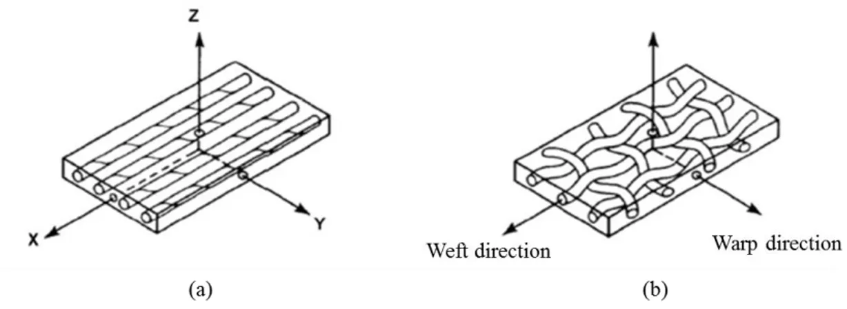
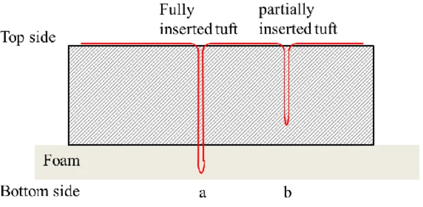
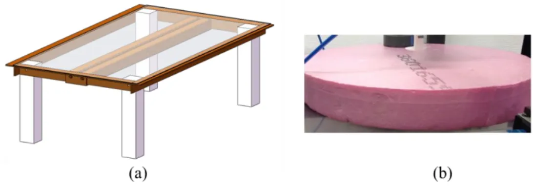
(30) Thèse de Lingshan Liu, Lille 1, 2017. 1. State of the art. bath and fabric reinforcement is dipped in the resin solution. By using a drying oven, the solvent is then evaporated off the prepreg [21]. The pre-impregnated processes are widely used in the civil and military fields, including the aeronautics sector, sports and leisure activities. High-level mechanical performance can be achieved by pre-impregnated technology. It is easy to control the properties of final parts, in particular the fibre volume fraction, but the cost of the storage and raw materials are very high.. 1.1.4 Textile preforms Composites consisting of fillers in the form of fibre or powder of relatively high strength and modulus embedded in or bonded to a matrix with distinct interface between them. [29]. .. In prepreg materials, fibres and resin are mixed together at the beginning. While for the LCM processes, reinforcing materials including mats, woven fabrics, braids, knitted fabrics and hybrid fabrics are needed. Figure 1-5 shows the fibres used to reinforce composites which are supplied in different forms: unidirectional (fabric UD), bidirectional (woven, braided), multiaxial (non-crimp fabrics, non-crimp new concept).. Figure 1-5 Different forms of reinforcement: (a) UD sheet, (b) mat, (c) woven fabric, (d) three-dimensional orthogonal woven fabric [8]. 18. © 2017 Tous droits réservés.. lilliad.univ-lille.fr.
(31) Thèse de Lingshan Liu, Lille 1, 2017. 1. State of the art. Textile preforming operations play a key role in most of the composite manufacturing processes. In textile process, there is direct control over fibre placements and ease of handling of fibres. Textile preform technologies provide homogenous distribution of matrix and reinforcing fibre. Thus, textile preforms are considered to be the structural backbone of composite structures. High performance multifilament fibres, such as glass, aramid and carbon fibres, which provide high tensile strength, modulus, and resistance to chemicals heat to various types of preforms, can be bound by necessary textile technologies. With textile preforming techniques, 2D/3D reinforced composites have achieved outstanding performances.. 1.2 Laminate fibre reinforced composites In reinforced composite material, reinforcement plays a role to fundamentally increase the mechanical properties. As previously mentioned, the typical used fibre material is carbon, glass, aramid, etc. Several thousand fibres are placed side by side with known directions and positions form textile reinforcement. Regarding the fabrication technology, the conventional textile technologies are used to design and manufacture fibre-reinforcements such as weaving, knitting, braiding and stitching. In terms of the alignment plans of the constitutive fibres, the fibre-reinforcement can be classified into three groups: 1D fibre reinforcement in which the fibre are parallel and aligned in one direction; 2D fibre reinforcement in which the fibre are aligned on one plane of the structure (XY plane); and 3D fibre-reinforcement in which a set of fibres are aligned along the orthogonal axis (Z axis) corresponding to through thickness axis of the structure [31]. .. The laminated fibre reinforced composites are 2D structures which have been used for over 65 years in maritime craft, aircraft, automobiles and civil infrastructures. It becomes the majority of highly structural sectors because of the high stiffness and strength at lowdensity, high-specific energy absorption behavior and excellent fatigue performance [32]. As a two-dimensional layered fibre structure, the laminated fibre reinforcement is made by stacking various laminas one upon the other in specific order and relative orientation which is illustrated in Figure 1-6. Each ply can be a unidirectional layer of paralleled long continuous fibres aligned on one plane, or a layer of conventional 2D woven fabrics, as shown in Figure 1-7. The orientation of the lamina refers to the orientation of the 19. © 2017 Tous droits réservés.. lilliad.univ-lille.fr.
(32) Thèse de Lingshan Liu, Lille 1, 2017. 1. State of the art. longitudinal axis of the fibres in the case of unidirectional lamina. While in the case of 2D woven fabric, it refers to the orientation of the longitudinal axis of the warp yarns. The orientation of stacked laminas could vary between -90°and +90°.. Figure 1-6 Laminate made by stacking laminas in different orientation. [33]. Figure 1-7 Lamina fibre reinforced composite: (a) lamina with unidirectional fibre; (b) lamina with 2D woven fabric. [33] Before lay-up process, unidirectional lamina made by filaments is usually saturated with resinous material which is called prepregs. The resinous materials are used as matrix which helps to maintain the aligned filaments in parallel and allows the easily handling in the next process.. 20. © 2017 Tous droits réservés.. lilliad.univ-lille.fr.
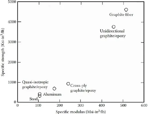
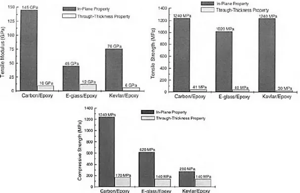
(33) Thèse de Lingshan Liu, Lille 1, 2017. 1. State of the art. The lay-up process consists of laying dry fabric layers or prepreg plies, onto a tool in specific orientation to form a laminate stack. For prepregs, filaments are already saturated with matrix material. While for dry piles, resin is applied after layup is complete. The principle lay-up processes include winding, laying and molding [33, 34]. Curing process consists of solidification of the matrix material to get the final rigid desired shape. Several curing methods are available. Cure can be accelerated by applying heat, typically with an oven, and pressure, by means of a vacuum. The laminate composites provide a number of advantages. Comparing to metallic materials, the laminate composite presents high in-plane specific strength and high in-plane specific stiffness. In Figure 1-8, the comparison of specific strength and specific modulus between metallic materials (steel and aluminum) and laminate composite (graphite fibre, unidirectional graphite/epoxy lamina and cross-ply graphite/epoxy laminate) is illustrated [35]. . The initial cost of the laminate composite material (raw material, design, fabrication. and assembly) as well the operating cost is lower than in comparison with metallic materials. [33]. . The laminate composites have a light weight but high specific strength and. specific stiffness which are used for transport applications to save the fuel cost. But the use of laminate composites in many structural applications has been limited by their several drawbacks. As a directional material, its mechanical properties are not identical in all direction and they depend on the fibres directions which is the principal drawback. Their application in some critical structures in aircraft and auto mobiles has been restricted due to the absence of the through-thickness fibre reinforcement which reduces delamination resistance, damage tolerance, impact resistance and post impact properties. [32, 36-38]. . As presented in Figure 1-9, the strength and stiffness properties, in the. through-thickness direction of the laminate, are often less about 10% of the in-plane properties. [34]. . Poor post impact mechanical properties of the laminates by showing the. degradation of the in-plane tensile and compressive strength after impact are illustrated in Figure 1-10. [34]. . Another drawback of the laminate composites is the increasing cost of. forming a complex part shape because of the process of assembling and the high labor requirement [33]. In some industries, particularly the aircraft industry, the production cost is increased when fabricating laminates from prepreg tape, because expensive refrigeration facilities are needed to prolong the shelf lives of the prepreg before the resin begins to cure. This is a major problem in the aircraft industry, where structures such as wings need to be 21. © 2017 Tous droits réservés.. lilliad.univ-lille.fr.
(34) Thèse de Lingshan Liu, Lille 1, 2017. 1. State of the art. made from a large number of smaller composite parts such as skin panels, stiffeners and stringers, rather than being fabricated as a single integral structure. [32]. . Furthermore, the. laminate composites present high thermal and moisture expansion coefficient and low operating temperature when use polymer matrix [35].. Figure 1-8 Specific strength in function of specific modulus of fibre, lamina, laminate and metals. [35]. 22. © 2017 Tous droits réservés.. lilliad.univ-lille.fr.
(35) Thèse de Lingshan Liu, Lille 1, 2017. 1. State of the art. Figure 1-9 Comparison of the in-plane tensile modulus, tensile strength and compressive strength to that in the through thickness properties for laminate composite materials. [35]. Figure 1-10 Degradation of the in-plane tensile and compressive strength after impact normalized to the strength before impact in function of the impact energy. [35]. 1.3 The 3D reinforcements In an attempt to overcome the problems appeared in laminate composites, the second generations of materials, 3D textile reinforced composite materials are obtained by applying highly productive textile technologies in the manufacture of fibre preforms. [32]. .. 23. © 2017 Tous droits réservés.. lilliad.univ-lille.fr.
(36) Thèse de Lingshan Liu, Lille 1, 2017. 1. State of the art. The aim of 3D reinforcement is to introduce reinforcements on the third direction by using through-thickness fibres to improve their damage tolerance and the impact resistance. The simplest method is to insert fibrous structure through the thickness between the different plies of the composite laminate, this link being a stiff carbon fibre rod in the case of Zpinning [40-43], or a thread (glass, carbon or aramid) in the case of stitching or tufting. [43-45]. .. These fabrics are sometimes referred to as 2.5D fabrics, as the amount of fibres in the thickness direction is less than the fibres in the planar direction of the fabric [2]. Because of the existence of reinforcements in the thickness direction, the damage tolerance and the impact resistance are increased since the trend to delamination is drastically diminished [39]. The fully integrated system where fibres are oriented in various in-plane and out-of plane directions is called 3D structures. The additional reinforcement in the through-thickness direction makes the composite virtually delamination-free. Fully integrated 3D textile structures such as 3D woven, knits, braids and non-wovens can assume complex structural shapes [2]. Composite structures made with 3D textile fabrics are potentially less expensive to manufacture and provide better through-thickness mechanical properties compared to composites made with the traditional 2D fabrics. [32]. . The through-thickness fibres inserted. by using a variety of textile processes, including 3D weaving, knitting, braiding, stitching or by specialist techniques such as z-pinning and tufting are introduced in this part.. 1.3.1 Woven fibre reinforced composites 3D woven fabric or multilayered fabric is composed of several in-plane woven layers linked together by yarns passing in the through thickness direction of the fabric called binder yarns or weaver yarns. According to different weave patterns for binder yarns, 3D woven fabrics can be classified into three categories: layer-to-layer angle interlock, through-the-thickness angle interlock and orthogonal, as shown in Figure 1-11. In layer-tolayer angle interlock, the binder yarn passes from a layer to adjacent one, then it returns to the first layer thus it links just two adjacent layers. In through-the-thickness angle interlock, binder yarns pass through whole the thickness of the fabric across more than two columns of weft yarns. In orthogonal, binder yarn passes through whole the thickness of the fabric for each column of weft yarns. There is no interlacing between warp and weft yarns and they are straight and perpendicular to each other. Z-yarns combine the warp and the weft layers by interlacing along the y-direction over the weft yarn. Interlacing occurs on the top and the bottom surface of the fabric [46-49]. 24. © 2017 Tous droits réservés.. lilliad.univ-lille.fr.
(37) Thèse de Lingshan Liu, Lille 1, 2017. 1. State of the art. Figure 1-11 Typical 3D woven architectures: (a) layer-to-layer angle interlock; (b) through-thickness angle interlock; (c) orthogonal. [31] The multilayered woven preform could be produced on a 3D weaving loom. Warp yarns are contained on a creel and fed into the weaving loom through a lifting mechanism, which selects and lifts the required yarns and creates a shed into which the weft yarns are inserted at right angles to the warp. The binder yarns can by aligned in the warp direction or inserted in the weft direction and their path through-the-thickness of the preform is controlled by the lifting sequence. [32] 3D weaving composites have many advantages comparing with 2D laminates. It can produce complex near-net-shape preforms, which can greatly reduce de cost of a component by reducing material wastage, the need for machining and joining, and the amount of material handled during lay-up. The binder yarn provides 3D woven composites with a high ballistic impact damage resistance, low-velocity impact damage tolerance, greatly increased tensile strain-to-failure values and higher interlaminar fracture toughness properties [32]. Guénon et al. [50] showed that even for low binder yarns content about 1% in 3D carbon/epoxy composite the delamination toughness for mode I is about 14% higher than for 2D carbon/epoxy prepreg laminates. Cox et al.. [51]. studied the failure mechanisms. of 3D woven carbon reinforced polymer composites on tension, compression and bending. They observed that the 3D woven composites exhibit high strain to failure in tension as well in compression. Lomov et al.. [52]. compared between non-crimp 3D orthogonal woven. composites and four-ply laminates of plain weave. He mentioned that 3D woven composites have a higher strength and failure strain.. 1.3.2 Knitted composites Knitting processes can be divided into two basic types: warp knitting and weft knitting (Figure 1-12). In weft knitting process, a single yarn is fed into the transversal direction of 25. © 2017 Tous droits réservés.. lilliad.univ-lille.fr.
(38) Thèse de Lingshan Liu, Lille 1, 2017. 1. State of the art. the knitting machine which forms a row of knit loop. In warp knitting process, multiple yarns are fed into the longitudinal direction of the machine and each yarn forms line of knit loops in the fabric direction.. Figure 1-12 (a) Shematic of weft knitted fabric; (b) shematic of warp knitted fabric 3D knitted composites can be divided into three types which are broadly categorized as sandwich, non-crimp and near-net-shape composites. With the existence of loop form, knitting composites have better formability and can produce more complex near-net-shape preforms. They can be produced on existing automatic machines with little modification. However many 3D knitting machines are under developed and cannot make thick preforms. Knitted composite exhibits fracture toughness greater than conventional 2D woven, unidirectional or random mat composite [32].And some types of 3D knitted composites have lower specific density, higher impact damage tolerance and energy absorption properties [53]. . 3D knitted composites generally have lower stiffness and strength properties. From the. experimental study weft knitted composites present a similar in-plane performance with the random mat composite, which is much lower than that of conventional 2D woven composite [54, 55]. Weft knitting of non-crimp fabrics causes breakages and distortions to the in-plane fibres [32].. 1.3.3 Braided composites Braiding was the first textile process used to manufacture a 3D fibre preform for a composite [32].. 26. © 2017 Tous droits réservés.. lilliad.univ-lille.fr.
(39) Thèse de Lingshan Liu, Lille 1, 2017. 1. State of the art. Figure 1-13 illustrates a conventional braiding machine. Braiding yarns are held on carriers which are placed on a circular platform. The warp carriers move in a counter-clockwise direction, and the weft carriers move in a clockwise direction to form a 2D braid construction. A mandrel is placed in the center of the braiding platform to allow the braid to be constructed on its entire surface. In the case of 3D braiding, the carrier platform contains several rows of carriers. The carriers travel from row to row, creating an interlocking of the two-by-two layers (Figure 1-14) [56].. Figure 1-13 (a) Overall view of a braiding machine (GEMTEX). (b) Description of the main elements of a braiding process [56].. Figure 1-14 (a) Outline of the carriers on a 3D braiding machine; (b) detailed view of the motion of a horn-gear during a 3D braiding operation [56].. 27. © 2017 Tous droits réservés.. lilliad.univ-lille.fr.
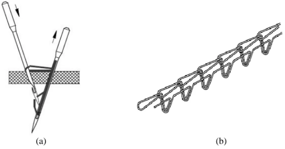
(40) Thèse de Lingshan Liu, Lille 1, 2017. 1. State of the art. Braided preforms have good conformability, drapability, torsional stability and structural integrity. It is possible to produce complex near-net-shape preforms, which makes the manufacturing cost considerably lower because it reduces the amount of fabric handling and material scrap as is the need for extensive machining and joining. [57]. . The mechanical. properties of the braided composite depend strongly on the amount of axial yarns, the angle of braided yarns and their braiding pattern. The 3D braid showed a less tensile strength in both directions and less transverse tensile modules, whereas the longitudinal compressive properties and tensile modulus were better than laminate. [43]. . 3D braiding. composites also have higher delamination resistance, better impact damage tolerance and lower notch sensitivity than 2D laminates because of the through-thickness reinforcement [32]. .. 3D braided composites have some limitations. One major limitation is that the preform size is relatively small because it depends on the braiding machine size, and most industrial machines are only capable of producing narrow preforms. Another limitation is the long set-up time of braiding machines. Some mechanical properties like stiffness and strength of 3D braided composites are generally lower than 2D laminates with an equivalent weight fraction of in-plane fibres [32].. 1.3.4 Stitched composites Stitched composites are 3D fibre reinforced composites produced by sewing high tensile strength yarn through an uncured prepreg laminate or dry fabric plies using an industrial sewing machine as illustrated in Figure 1-15. [43]. . Glass, carbon, polyester thread and. Aramid are typical reinforcing yarns. Different configuration of stitch could be sewed such as lock stitch, modified lock stitch and chain stitch. Through-thickness yarns have been stitched into composites with densities ranging from 0.4 to 25 stitches/cm2, by using a variety of sewing machines which can usually be classified as single-needle or multineedle machines [32, 43].. 28. © 2017 Tous droits réservés.. lilliad.univ-lille.fr.
Figure
![Table 1-2 Main characteristics of most used thermosetting resins [15,17]](https://thumb-eu.123doks.com/thumbv2/123doknet/3690545.109505/24.892.118.756.148.605/table-main-characteristics-used-thermosetting-resins.webp)
![Table 1-3 Typical properties of some reinforcement [17, 20]](https://thumb-eu.123doks.com/thumbv2/123doknet/3690545.109505/26.892.99.736.390.805/table-typical-properties-reinforcement.webp)

+7

Documents relatifs
The purpose of the present study is therefore to develop a patient-specific FE model of a standard cylindrical pedicle screw inserted in the lumbar vertebra, of which the
Figure 3.11 Influence of tufting pattern and density on the wrinkling phenomenon in the.. Figure 3.12 Influence of tufting pattern and density on the wrinkling phenomenon
tiques chimiqùes dans le traitement des cancers du sein. Si la tumeur n'est pas ulcérée, l'application de ces causti- ques sur la peau saine occasionne de vives
adipeux, de façon que les muscles conservaient leur- volume et augmentaient même parfois; cependant ce fait est plus rare, dans les lésions nerveuses périphé- riques que
L'état bosselé du foie n'est pas toujours un puissant auxiliaire au diagnostic, bien au contraire, et dans beaucoup de cas où nous rencontrons dans
La différence entre les résultats expérimentaux et numériques trouve peut-être ses origines, d’une part, dans les simplifications du modèle numérique (les valeurs des paramètres
The main of this work is study the mechanical behavior anddamage of tubular composite materials with glass fiber and organic matrix obtained by the filament winding
In this work theoretical and experimental studies of the behavior under static and fatigue conducted on prismatic specimens helped to highlight the effects of stacking sequences
