Université du Québec
Institut national de la recherche scientifique Énergie Matériaux Télécommunications
Reconfigurable Metamaterial-based Antenna Using
a Novel class of Miniaturized Agile Unit-cells
by
Behnam Zarghooni
A dissertation submitted in partial fulfillment of the requirements for the degree of Doctor of Philosophy (Ph. D.) in Telecommunications
Evaluation Jury
Research director Prof. Tayeb A. Denidni INRS-EMT
Internal examiner Prof. Serioja O. Tatu INRS-EMT
External examiner Prof. Cevdet Akyel
École Polytechnique de Montréal External examiner Dr. Michel Clénet
Defence Research and Development Canada
To my dear father Mr. Rahmatolah Zarghooni who inspired me to become
an engineer and to my dear mother Mrs. Touran Doroudgar who filled my heart
with love and affection and to my lovely wife and the biggest adventure of my life
Mahsa.
Abstract
In this thesis, a new class of reconfigurable and compact metamaterial unit-cells is introduced and used to present a novel technique for beam-switching antennas. Two metamaterial inspired antennas are designed and implemented using this technique at two different frequency bands i.e. S-band and millimeter-wave band.
The prospective role of reconfigurable unit-cells in the future of metamaterial theory is investigated and a novel reconfigurable metamaterial unit-cell is designed that can provide a controllable refractive index. Moreover, a novel miniaturization technique is introduced that can be applied on any rectangular-shaped metamaterial unit-cell. This technique is analytically investigated and a step-by-step guideline is provided. A combination of these two concepts is exploited to design a controllable metamaterial medium that can be easily integrated in the structure of planar antennas.
As the final objective of this work, the aforementioned artificial medium is embedded on the substrate of a planar dipole antenna and a radiation-pattern reconfigurable antenna with a switchable beam in the E-plane is designed and implemented in the S-band. The same technique is used at millimeter waves and an antenna with deflected beam in this band is presented.
Both antenna structures are fabricated and measured to validate the simulation results. Also, the designed cells in the S-band are fabricated and the performance of the unit-cells is verified by a modified version of the well-known free-space measurement method. Two custom-made dielectric lenses are designed and fabricated for this method. Furthermore, an analytical model is derived to explain the beam-tilting effect produced by the metamaterial unit-cells. This model successfully describes the behavior of both antennas at the vicinity of the metamaterial unit-cells.
Table of Contents
Chapter 1 Introduction1.1. Motivation 1
1.2. Problem statement and research Objectives 3
1.3. Organization of the Dissertation 4
1.4. List of Publications 5
Chapter 2 Reconfigurable Antennas
2.1. Introduction 8
2.2. Reconfigurable Antennas 9
2.2.1. Frequency Reconfigurable Antennas 9
2.2.2. Radiation-pattern Reconfigurable Antennas 10
2.2.3. Polarization Reconfigurable Antennas 11
2.3. Conclusion 11
Chapter 3 Millimeter Waves
3.1. Introduction 13
3.2. Tendency towards Millimeter Waves 14
3.3. Reconfiguration Techniques at Millimeter Waves 15
3.4. Conclusion 17
Chapter 4 Metamaterials
4.1. Introduction 18
4.2. History 19
4.3. Characterization of Metamaterials 20
4.3.1. The Lorentz Model 20
4.3.2 Constitutive Parameters of bulk Metamaterials 22
4.3.3. Extraction of Metamaterial Constitutive Parameters 25 4.4. Common Unit-cell geometries for bulk Metamaterials 26
4.5. Metamaterial Applications 29
4.5.1. Gain Enhancement 29
4.5.3. Beam tilting 29
4.5.4. Mutual Coupling Reduction 30
Chapter 5 Stepped-Impedance Resonator (SIR) Technique, for miniaturization of Rectangular Metamaterial Unit-cells
5.1. Introduction 31
5.2. SIR Technique 32
5.3. Effect of Higher modes 36
5.3.1. Short-circuited Stub 37
5.3.2. Open-circuited Stub 39
5.4. Case study: effect of the SIR technique on a rectangular BC-SRR and a circular ring
40
5.4.1. SIR effect on BC-SRR 41
5.4.2. SIR effect on a three-turn circular spiral 44
5.5. Conclusion 49
Chapter 6 The Unit-cell Structure
6.1. Introduction 51
6.2. The Unit-cell in S-band 52
6.2.1. The Reconfigurable Unit-cell 53
6.2.1.1. Design 53 6.2.1.2. Simulation 55 6.2.1.3. Experiment 63 6.2.2. SIR-based Unit-cells 68 6.2.2.1. Design 68 6.2.2.2. Simulation 70 6.2.2.3. Experiment 73 6.3. Conclusion 74
Chapter 7 The Antenna Structure
7.1. Introduction 76
7.2. Beam tilting Mechanism using a double-sectioned metamaterial medium in front of the antenna
77
7.3. The S-band antenna without unit-cell loading 79
7.3.1. Antenna with non-SIR Unit-cells 79
7.3.1.1. Antenna Design 79
7.3.1.2 Parametric Study 84
7.3.2. Antenna with SIR Unit-cells 86
7.4. The Millimeter-Wave Antenna Design 89
7.5. Comparison with Phased Array Technique 97
Chapter 8 The Paraffin Lens
8.1. Introduction 99
8.2. Lens Design and Simulation 100
8.3. Implementation of the Lens 104
8.4. Conclusion 106
Chapter 9 Conclusion and Future Research
9.1. Conclusion 107
9.2. Future Research 109
Chapter 10 Résumé
10.1. Introduction 110
10.1.1.Motivation 110
10.1.2. Identification du problème et objectifs de recherche 112 10.2. Technique de résonateur à impédance échelonnée pour la
miniaturisation d'une cellule métamatériau
114
10.2.1. Effet de la technique sur une cellule 114
10.2.2. Le rôle de l'impédance caractéristique 116
10.2.3. Effet des modes supérieurs 118
10.2.3.1. Le stub à court-circuit 118
10.2.3.2. Le stub à circuit ouvert 121
10.3. Conception de la cellule métamatériau 123
10.3.1. Les cellules avec des diodes idéales 123
10.3.2. Les cellules avec les diodes réelles 129
10.4. Antenne reconfigurable à bande S 131
10.5. Antenne avec les cellules SIR 135
10.6. Antenne en métamatériaux aux ondes millimétriques 137
10.7. Lentille diélectrique 143
10.8. Conclusion 146
10.9. Axes pour les traveaux futures 146
List of Figures
Fig. 1.1. Detachable beam-tilting unit 3
Fig. 3.1. Average atmospheric attenuation versus frequency [32]. 14
Fig. 4.1. Array of thin wires 23
Fig. 4.2. The constitutive parameters of the thin wire array 23
Fig. 4.3. Array of Split-ring resonators 24
Fig. 4.4. The constitutive parameters of the split-ring resonator array. 24
Fig. 4.5. Broadside-coupled SRR. 27
Fig. 4.6. Axially Symmetric SRR. 27
Fig. 4.7. Omega-shaped Resonator. 28
Fig. 4.8. S-shaped Resonator. 28
Fig. 4.9. The Snell's law of refraction. 29
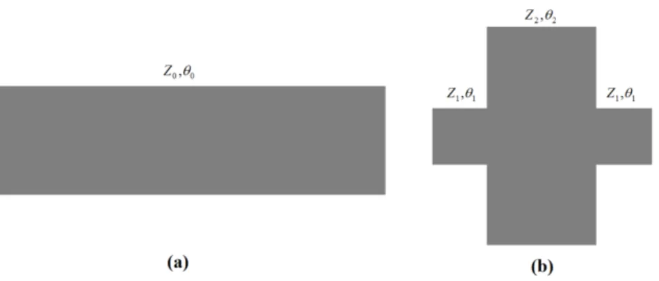
Fig. 4.10. Metamaterials for beam-tilting applications. 30 Fig. 5.1. A conventional microstrip line (a) and its equivalent SIR
configuration (b).
32
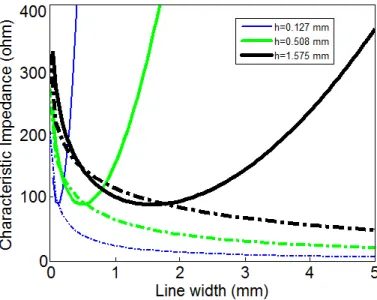
Fig. 5.2. The Paired strip transmission line [80]. 33
Fig. 5.3. The characteristic impedance of the paired-strip versus the line width.
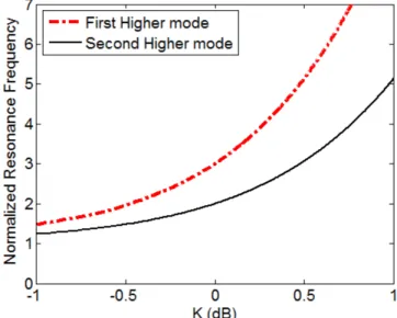
34 Fig. 5.4. Miniaturization factor for different values of M and K. 36 Fig. 5.5. The SIR configuration and its possible resonances. 36 Fig. 5.6. The normalized resonance frequency versus impedance ratio
for the first resonance when the stub is short-circuited.
38 Fig. 5.7. The normalized resonance frequency versus impedance ratio
for the second resonance when the stub is short-circuited.
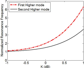
39 Fig. 5.8. The normalized resonance frequency versus impedance ratio
for the second resonance when the stub is open-circuited.
40 Fig. 5.9. A comparison between Conventional SRR (a), BC-SRR (b)
and SIR-SRR (c) unit-cells.
41 Fig. 5.10. The S-parameters of the conventional SRR (a), BC-SRR (b)
and SIR-SRR (c).
42 Fig. 5.11. The schematic view of the SIR-BC-SRR unit-cell. 43 Fig. 5.12. The simulated S-parameters for SIR-BC-SRR unit-cell. 44
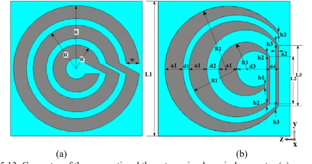
Fig. 5.13. Geometry of the conventional three-turn circular spiral resonator (a) compared to the proposed crescent-shaped unit-cell (b).
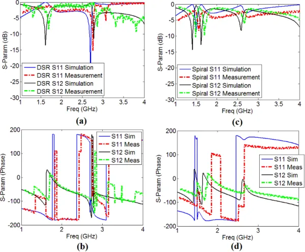
45 Fig. 5.14. The parameters S11 and S12 for crescent-shaped (a,b) and
spiral unit-cell (c,d).
46 Fig. 5.15. The current distribution for spiral (a) and crescent-shaped
unit-cell (b).
47 Fig. 5.16. The extracted constitutive parameters of the crescent-shaped
(a,b,c) and spiral unit-cell (d,e,f).
48
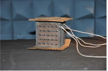
Fig. 5.17. The fabricated crescent-shaped prototype. 49
Fig. 6.1. A sample circular unit-cell in (a) DSR and (b) Spiral format (dimensions in mm: L=10, rout=4.5, rin=3.5, w=0.5, 5=0.5).
52 Fig. 6.2. The Simulated S-parameters of DSR and Spiral unit-cells. 53 Fig. 6.3. The structure of the presented reconfigurable unit-cell. 54 Fig. 6.4. Three configurations of the presented unit-cell. 54 Fig. 6.5. The S-parameters and effective refractive index for DSR 55 Fig. 6.6. The S-parameters and effective refractive index for quasiDSR 56 Fig. 6.7. The S-parameters and effective refractive index for Spiral 57 Fig. 6.8. The current distribution on different configurations of
unit-cell.
59
Fig. 6.9. The lumped-element model for the diodes. 59
Fig. 6.10. The unit-cell with bias network. 60
Fig. 6.11. The S-parameters and refractive index for unit-cell in DSR configuration.
61 Fig. 6.12. The S-parameters and refractive index of unit-cell in spiral
configuration.
62 Fig. 6.13. The fabricated prototype for measurement of S-parameters. 64
Fig. 6.14. The Measurement Results 65
Fig. 6.15. The fabricated reconfigurable unit-cell array. 66 Fig. 6.16. Measured parameters of reconfigurable unit-cells. 67
Fig. 6.17. SIR design curves. 68
Fig. 6.18. The SIR-DSR and SIR-Spiral structures. 69
Fig. 6.19. The S-parameters and refractive index for SIR-DSR 70 Fig. 6.20. The S-parameters and refractive index for SIR-Spiral 72
Fig. 6.21. The fabricated SIR-based unit-cell 73
Fig. 6.22. The measurement results for SIR Structures. 73 Fig. 7.1. Mechanism of beam tilting using two layered dielectric
media.
78 Fig. 7.2. Schematic view of the antenna top (a) and bottom (b). 79 Fig. 7.3. Antenna with metamaterial unit-cells, (a) top and (b) bottom. 80 Fig. 7.4. The radiation pattern of the antenna loaded with metamaterial
unit-cells at 3 GHz.
81 Fig. 7.5. Photograph of the antenna with metamaterial loading. 82
Fig. 7.6. Normalized Radiation pattern of antenna at: (a) 2.8 GHz, (b) 3 GHz, and (c) 3.2 GH, and (d) H-plane at 3 GHz.
83 Fig. 7.7. Measured reflection coefficient of the antenna with and
without metamaterial.
84
Fig.7.8. Parametric study on number of rows. 85
Fig. 7.9. Parametric study on distance between the antenna and unit-cells.
85 Fig. 7.10. The schematic view of the antenna with SIR unit-cells. 86 Fig. 7.11. Radiation pattern of antenna loaded with SIR unit-cells. 87 Fig. 7.12. Reflection coefficient of antenna SIR metamaterial. 88 Fig. 7.13. The reference antenna at millimeter waves. 90
Fig. 7.14. The schematic view of the MMW unit-cells. 90
Fig. 7.15. The simulated S-parameters Magnitude (a) and phase (b). 91 Fig. 7.16. Extracted effective parameters of the unit-cells. 92
Fig. 7.17. The two-sectioned metamaterial medium. 93
Fig. 7.18. Normalized Measured and Simulation radiation pattern in the E-plane.
94 Fig. 7.19. Normalized radiation pattern in the H-plane. 94 Fig. 7.20. Reflection coefficient of the antenna with and without
metamaterial.
95 Fig. 7.21. Poynting vector of the antenna with metamaterial unit-cells. 95 Fig. 7.22 The fabricated prototype at millimeter waves. 96 Fig. 7.23. The eight-element angled-dipole array derived from [91]. 97 Fig. 8.1. Schematic view of the free-space measurement setup. 100 Fig. 8.2. Lens design flowchart conventional method (a) our method (b). 102
Fig. 8.3. The simulated Poynting vector of the lens 103
Fig. 8.4. Photograph of the molding process used to fabricate the lens. 104 Fig. 8.5. The fabricated lens front view (a), and Top view (b) 105 Fig. 8.6. Paraffin dielectric lenses used in the measurement setup 106 Fig. 10.1. Bloc de reconfiguration dans un système modulaire 113 Fig. 10.2. Une ligne microruban classique, et sa structure échelonée 114 Fig. 10.3. Facteur de miniaturisation pour les différentes valeurs de M
et K
116 Fig. 10.4. Ligne de transmission ruban-jumelé (paired-strip) 116 Fig. 10.5. Impédance caractéristique de la ligne ruban-jumelé (ligne
continue) par rapport à microruban (ligne pointillée)
117
Fig. 10.6. Résonateur à impédance échelonée 118
Fig. 10.7. Fréquence de résonance normalisée par rapport à K dans le cas de court circuit
120 Fig. 10.8. Fréquence de résonance normalisée par rapport à K dans le
cas de circuit ouvert
Fig. 10.9. Fréquence de résonance normalisée par rapport à K dans le cas de circuit ouvert
122 Fig. 10.10. Trois configurations possibles pour la cellule 123 Fig. 10.11. Paramètres simulés pour la cellule DSR idéale 124 Fig. 10.12. Paramètres simulés pour la cellule quasi-DSR idéale 125 Fig. 10.13. Paramètres simulés pour la cellule spiral idéale 126 Fig. 10.14. Distribution du courant sur les cellules idéales 127 Fig. 10.15. Le prototype 3D fabriqué pour (a) Spiral et (b) DSR 128 Fig. 10.16. Résultats mesurés pour les cellules non-reconfigurables 128
Fig. 10.17. Structure de la cellule avec les diodes 129
Fig. 10.18. Réseau d'alimentation d'une cellule 129
Fig. 10.19. Les cellules reconfigurables fabriqués 130
Fig. 10.20. Les parametres mesurés des cellules reconfigurables 130
Fig. 10.21. Antenne sans les cellules métamatériaux 131
Fig. 10.22. Antenne avec les cellules reconfigurables 132 Fig. 10.23. Diagramme de rayonnement normalisé de l'antenne dans le
plan E à: (a) 2.8 GHz, (b) 3 GHz, (c) 3.2 GHz et (d) dans le plan H à 3 GHz
133
Fig. 10.24. Mécanisme de déviation du faisceau 134
Fig. 10.25. Coefficient de réflexion de l'antenne avec et sans des cellules métamatériaux
134
Fig. 10.26. Antenne avec les cellules miniaturisées 135
Fig. 10.27. Le diagramme de rayonnement et coefficient de réflexion de l'antenne avec les cellules miniaturisées
136 Fig. 10.28. Structure de l'antenne aux ondes millimétriques 137 Fig. 10.29. Structure de cellule métamatériau aux ondes millimétriques 138 Fig. 10.30. Paramètres S des cellules aux ondes millimétriques 139 Fig. 10.31. Indice de réfraction de (a) DSR et (b) spirale 140 Fig. 10.32. Diagramme de rayonnement de l'antenne aux ondes
millimétriques
141 Fig. 10.33. Coefficient de réflexion de l'antenne avec et sans
métamatérial
142 Fig. 10.34. Prototype fabriqué aux ondes millimétriques 142 Fig. 10.35. Schéma de la méthode espace-libre pour mesurer les
paramètres S des cellules métamatériaux
143 Fig. 10.36. Organigramme de (a) la méthode conventionnelle et (b) le
procédé de moulage qu'on a utilisé dans cette thèse
144 Fig. 10.37. Photo des lentilles fabriquées en utilisant le procédé de
moulage
List of Tables
Table. 5.1. Effect of the substrate permittivity on the unit-cell 47
Table. 6.1. The unit-cell dimensions 54
Table. 6.2. The parameters for the diode GMP4201 60
Table. 6.3. The dimensions of the SIR structure 69
Table. 7.1. Simulated antenna gain at S band 81
Table. 7.2. Measured antenna gain at S band 84
Table. 7.3. MMW antenna gain at different frequencies 96
CHAPTER 1. INTRODUCTION 1
Chapter 1
Introduction
1.1 Motivation
Today, modern telecommunication systems provide us with various functionalities such as high data-rate transmission, multiband performance and different diversities, but at the same time, it should be low-cost, robust, compact and easy to use. All these points show that if multiple functions can be preformed by a single system, the cost and complexity of the system can be reduced significantly. That is why intelligent systems have been deployed extensively in a variety of commercial, industrial and military applications. On the other hand, the antenna design is an inseparable part of any telecommunication system and improvement of this section can have a significant effect on the overall performance of the communication system. Therefore, employing reconfigurable antennas that are capable of providing diversity at different levels is a promising solution to enhance the system performance.
CHAPTER 1. INTRODUCTION 2
Based on the abovementioned facts, the research area of reconfigurable antennas has received ever-growing attention since several decades [1]. In fact, there are a lot of researches conducted on different aspects of reconfiguration such as radiation-pattern, directivity, polarization and frequency [2-5]. To achieve these objectives, various approaches including mechanically and electronically controlled antenna arrays or single elements have been used. In accordance with the application of the system, different techniques can be employed to implement each approach. However, it is needless to say that electrically controlled single agile antennas are always amongst the most interesting subjects due to their vast applications in modern communication systems in the form of independent antennas or array elements.
Millimeter-wave (MMW) bands (30-300 GHz) have drastically gained much focus and attracted researchers in the past few years. They have a great potential to meet the modern demands of emerging communication systems and applications. Beside the high-speed, large bandwidth and high capacity, at this regime, the integration of compact and high-efficiency antennas is very easy. These attributes make the millimeter-wave band a suitable choice for many applications such as Gigabit wireless communications, imaging sensors, automotive radars and deep-space communications [6-9]. All these systems require low-cost and high-efficiency integrated antenna solutions. Many millimeter-wave communication and radar systems require antennas with a reconfigurable radiation pattern to achieve beam-scanning or beam-shaping capabilities. Some examples are point-to-point and point-to-multipoint links, ground stations for satellites, automotive radars, deep-space communication links and Gigabit wireless indoor communication systems 43]. However, millimeter-wave bands suffer from the high attenuation characteristics associated with multipath fading, high conductor losses and mutual coupling problems. To overcome these issues and improving the system’s signal to noise ratio (SNR), bit-error rate (BER) and channel capacity, different aspects of reconfigurability such as frequency-reconfiguration, polarization reconfiguration, and pattern reconfiguration can be used.
On the other hand, in the last decade, metamaterials have provided novel solutions to overcome limitations and difficulties of conventional microwave components [10] and have been extensively used in a variety of antenna applications. Today, different types of metamaterials such as zero-index, high-index and low-index materials are used in different applications [11]. However, there is still more to achieve in the metamaterial theory and features such as nonlinear and reconfigurable metamaterials are to be explored [12]. Reconfigurable metamaterials have shown a great potential in providing features required in intelligent antenna and microwave components. Moreover, to reach the final goal of the metamaterial theory, which is imitating the behavior of the atoms, one must focus on the reconfigurable metamaterial structures.
CHAPTER 1. INTRODUCTION 3
The abovementioned matters about reconfigurable antennas and millimeter waves along with the extensive applications of metamaterials have motivated us to conduct a comprehensive research in the field of reconfigurable metamaterial antennas at S-band and also millimeter waves. Consequently, this project aims to design, fabricate and test a miniaturized and reconfigurable metamaterial unit-cell in the S-band and then use this unit-cell in an integrated structure with a planar single element antenna to provide the beam-switching capability. In addition to the S-band, this antenna will be simulated and implemented at millimeter wave frequencies. We will prove that this method of beam-switching has several advantages over other conventional methods including the very low-profile structure and being free from gain drop when the beam is tilted.
1.2. Problem statement and research objectives
Recent works in the literature have presented different techniques for beam-tilting applications in different frequency bands [13]. Using controllable metamaterial unit-cells can be a promising solution for beam-switching and at the same time gain enhancement [14]. On the other hand, to be able to integrate metamaterial unit-cells with modern compact-sized antennas used in today's telecommunication systems, the size of the unit-cell should be reduced as much as possible. Different methods have been used to reduce the size of metamaterial unit-cells such as using fractal and Greek-key structures [15]. However, no controllable method has been formulized until today. Designing a reconfigurable metamaterial unit-cell is another challenging task that can help us to obtain more agility and wider bandwidth from a single unit-cell [16]. Reconfigurable unit-cells also provide the possibility to design an independent and detachable reconfigurable unit that can be attached to or be separated from the main antenna unit as needed as shown in Fig 1.1.
CHAPTER 1. INTRODUCTION 4
In this work, a new class of compact and reconfigurable metamaterial unit-cells is introduced. The name of RMDS, which stands for Reconfigurable Miniaturized DSR-Spiral is chosen for the unit-cell, because it can switch between a compact DSR-Spiral and an optimized Double Split-ring Resonator (DSR). Both of these configurations are miniaturized using a novel algorithm developed in this thesis that is based on the application of stepped-impedance resonators (SIRs). This unit-cell is used as an integrated metamaterial loading, which can be controlled independently in front of a planar antenna. This mechanism provides a very effective method to control the antenna beam in its azimuth plane. It is important to mention that unlike other conventional methods of beam tilting, there is no gain drop in our proposed approach and in fact, even a slight gain enhancement is noticed when the beam is tilted. To prove the effectiveness of our method, two sets of unit-cells and antennas will be developed, functioning in the S-band and millimeter waves, respectively.
As the specific objectives of our project, the two designed antenna systems must operate at 2.45 GHz and 60 GHz, respectively. Both antennas provide a sweep on the whole azimuth plane with the step of 60o over a bandwidth of 15%, while the realized gain is kept more than 6 and 9 dB for the S-band and millimeter-wave prototype respectively. This feature is highly needed in adaptive antennas capable of providing space diversity.
1.3. Organization of the Dissertation
In this section, a short explanation on the organization of this thesis is presented and the purpose of each chapter is discussed. First and foremost in Chapter 2, a literature review is performed on the concept of reconfigurable antennas. In this chapter, different aspects of reconfiguration and the existing solutions for each aspect are investigated. Secondly in Chapter 3, a brief survey is done on the millimeter waves and a variety of the applications of this band in the modern communication systems are discussed. In this chapter, pattern reconfiguration is introduced as a suitable solution to overcome the problems of the millimeter-wave band and feasible methods of reconfiguration at this band are briefly discussed. Moreover in Chapter 4, a detailed study is presented on the concept of metamaterials and various applications of these structures in reconfigurable antennas and at millimeter wave frequencies are investigated. Following all the aforementioned chapters, a comprehensive study on our novel miniaturization technique for metamaterial unit-cells is presented in Chapter 5. Furthermore, the structure of stepped impedance resonators and their applications in metamaterial unit-cells are discussed and the issues of this method for miniaturization of metamaterial structures are studied. This chapter plays an important role in the organization of the thesis and its contents are used for the design
CHAPTER 1. INTRODUCTION 5
and implementation of our metamaterial structure. The Chapter 6 is totally devoted to design, simulation, fabrication and measurement of the novel RCSD cell. This unit-cell relies on DC-biased PIN-diodes to provide a reconfigurable structure. However, in this chapter first for the proof of the concept the unit-cells are replaced by short circuit and open circuit in the ON and OFF state, respectively and then real diodes are modeled and used in the structure of the unit-cell. Two different sizes of this unit-cell are presented for the S-band and the MMW band respectively. It has to be mentioned that the reconfigurable unit-cell at the MMW band is not in the scope of our work in this thesis and it will be used along with a dipole antenna to provide a millimeter-wave antenna with the tilted beam. The technique of multiple feed lines will be used to switch the beam of this antenna at the MMW band. After the design of the unit-cell, we focus on the design and implementation of the antenna in Chapter 7 and two different antennas are presented, one for each frequency band. The experimental and simulation results for all the prototypes are presented in the same chapter. In Chapter 7, we also try to reduce the effect of the bias network for the S-band antenna as much as possible. Finally, the work is concluded in Chapter 8 and a summary of the accomplishments of the thesis is presented. Furthermore in this chapter, some new ideas are introduced for possible future investigations. A detailed summary of the thesis is provided in Chapter 10 in French.
1.4 List of The Publications
[1] B. Zarghooni and T. A. Denidni, “New Compact Metamaterial Unit-cell Using SIR Technique,” IEEE Microw. Compon. Lett., vol. 24, no. 5, pp. 3150317, March 2014. [2] B. Zarghooni, A. Dadgarpour and T. A. Denidni, "Effect of Stepped-Impedance Resonators on Rectangular Metamaterial Unit-cells," Wiley Intl. Journal of RF &
Microw. Computer Aided Eng. Feb. 2015.
[3] B. Zarghooni, A. Dadgarpour and T. A. Denidni, “Greek-key Pattern as a Miniaturized Multiband Metamaterial Unit-cell,” IEEE Antennas Wireless Propag. Lett. vol. 14, pp. 1254-1257, Feb. 2015.
[4] B. Zarghooni, A. Dadgarpour and T. A. Denidni, "Reconfigurable Planar Metamaterial Unit-cell," IET Microw. Antennas Propag., March 2015.
[5] B. Zarghooni, A. Dadgarpour and T. A. Denidni, "Beam-switching Antenna Using Reconfigurable Metamaterial Unit-cells," Submitted to IEEE Trans Antennas Propag., Aug 2015.
CHAPTER 1. INTRODUCTION 6
[6] B. Zarghooni, A. Dadgarpour and T. A. Denidni, "Dielectric Lens for Metamaterial Measurement," Submitted to IEEE Trans Antennas Dielectric and Insulation, June 2015. [7] B. Zarghooni, A. Dadgarpour and T. A. Denidni, “Millimeter-wave Antenna Using Two-Sectioned Metamaterial Medium,” Accepted with revision in IEEE Antennas
Wireless Propag. Lett. May 2015.
[8] B. Zarghooni, A. Dadgarpour and T. A. Denidni, “Crescent-Shaped Metamaterial Unit-cell,” Submitted to IEEE Antennas Wireless Propag. Lett. May 2015.
[9] B. Zarghooni and T. A. Denidni, “Supershaped Metamaterial Unit-cells Using the Gielis Formula,” in IEEE Int. Symp. on Antennas and Propag. (APSURSI), Vancouver, Canada, July 2015.
[10] B. Zarghooni and T. A. Denidni, “Reconfigurable Metamaterial Dipole Antenna,” in IEEE Int. Symp. on Antennas and Propag. (APSURSI), Memphis, USA, July 2014. [11] T. A. Denidni and B. Zarghooni, “Stepped Impedance Resonator Technique for Metamaterial Miniaturization,” invited paper in Int. Symp. on Antenna Tech. and Applied
Electromagnetics (ANTEM), Victoria, Canada, July 2014. (Invited Paper)
[12] B. Zarghooni and T. A. Denidni, “New Fractal Metamaterial Unit-cell for Microwave Applications,” in European Conference on Antennas Propag. (EuCap), April 2014.
[13] B. Zarghooni and T. A. Denidni, “Miniaturized DNG Superstrate for Microstrip Antenna Applications,” in IEEE Int. Symp. on Antennas and Propag. (APSURSI), Orlando, USA, July 2013.
[14] B. Zarghooni and T. A. Denidni, “Design and Simulation of Novel Compact Unit-cell for DNG Metamaterials based on Stepped-Impedance Resonator Technique,” in
IEEE Int. Symp. on Antennas and Propag. (APSURSI), Chicago, USA, July 2012.
[15] B. Zarghooni and T. A. Denidni, “Agile Double Negative Metamaterial Unit-cell for Advanced Antenna Applications,” in Int. Symp. on Antenna Tech. and Applied
Electromagnetics (ANTEM), Toulouse, France, June 2012.
[16] B. Zarghooni and T. A. Denidni, “Design and simulation of Novel Compact and Reconfigurable Double Negative Metamaterial Unit-cell,” in Int. Conf. on Metamaterials Photonic Crystals and Plasmonics (META), Paris, France, April, 2012.
CHAPTER 1. INTRODUCTION 7
[17] B. Zarghooni and T. A. Denidni, “A partially filled substrate for a rectangular patch antenna,” in IEEE Int. Symp. on Antennas and Propag. (APSURSI), Washington, USA, July 2011.
[18] A. Dadgarpour, B. Zarghooni, B. S. Virdee and T. A. Denidni, “Beam Tilting Antenna using Integrated Metamaterial Loading,” IEEE Trans. Antennas Propag., vol. 62, no. 5, pp. 2874-2879, Feb. 2014.
[19] A. Dadgarpour, B. Zarghooni, B. S. Virdee and T. A. Denidni, “Millimeter-Wave High-Gain SIW End-Fire Bow-tie Antenna,” IEEE Trans. Antennas Propag., vol. 63, no. 5, pp. 2337-2342, Feb. 2015.
[20] A. Dadgarpour, B. Zarghooni and T. A. Denidni, "High-gain end-fire bow-tie antenna using artificial dielectric layers," IET Microw. Antennas Propag., May 2015. [21] A. Dadgarpour, B. Zarghooni, B. S. Virdee and T. A. Denidni, “Beam-Deflection Using Gradient Refractive-Index Media for 60 GHz End-Fire Antenna,” IEEE Trans.
Antennas Propag., June. 2015.
[22] A. Dadgarpour, B. Zarghooni and T. A. Denidni, “Mutual-Coupling suppression for 60 GHz MIMO Antenna using Metamaterials,” in IEEE Int. Symp. on Antennas and
Propag. (APSURSI), Vancouver, Canada, July 2015.
[23] A. Dadgarpour, B. Zarghooni and T. A. Denidni, “Beam forming bow-tie antenna for Millimeter-wave Applications using Metamaterial Lens,” in IEEE Int. Symp. on
Antennas and Propag. (APSURSI), Vancouver, Canada, July 2015.
[24] A. Dadgarpour, B. Zarghooni and T. A. Denidni, “High gain planar Bow-tie Antenna Using Zero-index Metamaterials,” in IEEE Int. Symp. on Antennas and Propag.
(APSURSI), Memphis, USA, July 2014.
[25] A. Dadgarpour, B. Zarghooni and T. A. Denidni, “High Gain End-fire Bow-tie Antenna Array Using Low-index Metamaterial,” in Int. Symp. on Antenna Tech. and
CHAPTER 2. RECONFIGURABLE ANTENNAS 8
Chapter 2
Reconfigurable Antennas
2.1. Introduction
In recent years, demands on high quality, low cost, and high data rate communication systems, capable of adapting to unpredictable environment conditions have led to rapid growth of some attractive research subjects called adaptive or reconfigurable antennas [17,18]. The purpose of these research areas is to overcome the restrictions of conventional antennas. Of course there are some efficient techniques to use non-reconfigurable antennas in smart arrangements such as phased array systems, but using smart antennas as elements of these intelligent networks, can lead to better parameters such as scan angles and considerably enhance the overall performance of the communication system. On the other hand, if a single reconfigurable element is used instead of an intelligent array, the cost and complexity of the system can be significantly reduced.
CHAPTER 2. RECONFIGURABLE ANTENNAS 9
In this chapter, the reconfigurable antennas are divided into three main groups from the aspect of the adjustable parameters i.e. bandwidth of operation, radiation-pattern and polarization. Moreover, the most common methods for each group is presented and discussed. Finally, a brief discussion about reconfigurable antennas in the millimeter-wave bands is deliberated.
2.2. Reconfigurable Antennas
2.2.1. Frequency-Reconfigurable Antennas
Today, in modern telecommunication systems, we can see many conditions where a system works in different frequency bands. The simplest scenario is the case where a transceiver transmits signals in one frequency and receives at another frequency. In this case, instead of using a separate antenna for each band, a frequency-reconfigurable antenna is used to reduce the system cost and also make it easier to implement and less bulky. The most important objective in the design of these antennas is to keep the desired radiation-pattern and polarization characteristics over all the operational frequency bands. This is a challenging task because normally the physical size of the antenna cannot be easily modified during the operation. Of course it is always possible to use mechanical switches to actually change the antenna’s physical characteristics, but the alternative solution is to modify the current distribution on the antenna and change the electrical length of the structure.
Techniques in Frequency-Reconfigurable Antennas
All the various techniques used in frequency reconfiguration can be categorized in three main groups: mechanical approaches, electrical techniques and finally the methods that work on controlling the properties of the materials used in the antenna’s structure.
In the mechanical methods, the antenna structure is moved or reshaped by means of electromechanical switches. As two examples of these methods, we can mention Piezo-electric actuators [19, 20] and micro-machined plastic deformation [21]. The main advantage of mechanical frequency-reconfiguration methods is that they can cover a wide range of frequencies. The other benefits of these techniques are their relatively low loss, linear behavior and low inter-modulation harmonic level. However, their major drawbacks, i.e. bulky structures and low switch speed of the actuators make them incompatible with most of modern applications.
The electrical methods usually use an array of controllable switches such as PIN-Diodes FETs and radio frequency micro-electro-mechanical switches (RF-MEMS) or variable
CHAPTER 2. RECONFIGURABLE ANTENNAS 10
capacitors. These methods are much faster than mechanical methods but they have their own drawback, which is the requirement of a relatively complicated biasing network to control the switch elements.
2.2.2. Radiation-pattern Reconfigurable Antennas
Another interesting subject in smart antennas is the radiation-pattern reconfiguration. This term is used for beam-steering techniques as well as methods for controlling the antenna gain in both azimuth and elevation planes. The purpose of the radiation-pattern reconfigurable antennas is usually enhancing the link quality by simply focusing the signals to a desired direction, or to be able to alter the gain to change the coverage area. It is evident that the main method to implement these features is to control the current distribution of the antenna, which in turn leads to modify the frequency behavior and consequently the impedance matching of the antenna. Therefore, keeping the desired matching properties has to be considered when the beam or gain of the antenna is being changed.
Techniques in Radiation-Pattern-Reconfigurable Antennas
As for the frequency reconfiguration, various electrical or mechanical methods can be used to provide a reconfigurable pattern. Imagining a mechanical approach to steer the beam of the antenna is pretty easy, and all we need is to mount the antenna on a rotating structure. However, same as the previous section, these structures have the important drawback of being bulky and low-speed. Therefore, using electrically controlled elements and materials should be considered for modern communication systems. Active elements such as PIN-diodes RF-MEMS, and controllable media such as ferroelectric, ferromagnetic [22-24] are some of the common methods that are used in the literature. There is also one more and very important method of configuration for this type of reconfigurable antennas i.e. phased array approach. In this method, a linear or multi-dimensional array of antennas is used along with a controlled feed network, which adjusts the phase of each element. The outcome of this system is the ability to control the direction of the radiated electromagnetic waves from the antenna. The phased array method is free of some of the above-mentioned difficulties for other methods. However, in this method the design of phase shifters is a challenging task and involves a lot of loss. One other interesting method that can be used to modify the radiation pattern of an antenna is to utilize a reconfigurable artificial medium in vicinity of the antenna. Examples are reconfigurable EBG structures with controllable PIN-diodes around a dipole antenna to actively change the direction of the antenna beam [25-29]. However,
CHAPTER 2. RECONFIGURABLE ANTENNAS 11
these EBG structures have their own drawbacks which include having a large-sized unit-cell compared to the wavelength, and the negative effect of the bias network that is used to control active unit-cells on the antenna parameters.
On the other hand, metamaterial structures possess very small unit-cells compared to the wavelength (λ/10), which enable us to reduce the size of the bias network. Moreover, Reconfigurable metamaterials provide the unique ability to control the effective constitutive parameters of the medium which can be very helpful to deflect and steer the antenna's beam in a desired direction.
2.2.3. Polarization-Reconfigurable Antennas
Antennas with the polarization-reconfigurable capability are used when we need to avoid the interfering signals in unpredictable environment conditions and also to provide additional degrees of freedom for antenna diversity to enhance a link quality. Polarization-reconfigurability is realized by controlling the direction of the current distribution. This is usually done by modifying the antenna itself, or the feed network. The main challenge in designing these types of antennas is to keep a good impedance matching and radiation-pattern while the polarization reconfigurability is maintained. Techniques in Polarization-Reconfigurable Antennas
According to the available reported researches, switching techniques are among the most practical approaches to design and implement polarization-reconfigurable antennas. These methods include the application of electrically controlled elements such as PIN-diodes and RF-MEMS. Other techniques such as mechanical methods and controlling material properties are not so popular because of the difficulty of implementation and due to a high level of loss.
2.3. Conclusion
According to the survey done in this chapter, design and implementation of reconfigurable single-element antennas is a challenging task and more research is needed to be conducted in this field. The current feasible methods for reconfiguration of different parameters of the antennas suffer from high cost and complexity level, which makes it crucial to tend to novel techniques for this purpose. Using the new approaches like reconfigurable metamaterials not only enables us to exploit adaptive antennas as components of intelligent phased-array systems, but also help us to have single-element
CHAPTER 2. RECONFIGURABLE ANTENNAS 12
smart antennas, which can be extremely useful in the design and implementation of low-cost, high-performance, and low-profile telecommunication systems.
CHAPTER 3. MILLIMETER WAVES 13
Chapter 3
Millimeter Waves
3.1. Introduction
As mentioned in the objectives, one of the important goals of this thesis is to present a low-profile and efficient solution for reconfiguration of the radiation pattern in the millimeter-wave frequency band. More precisely, this design can be used for future generation of indoor Gigabit wireless LAN networks [30]. In this chapter, first the ever-growing tendency toward the millimeter waves is studied and the applications of this frequency band are briefly explained and then, the feasible reconfiguration techniques for this band are investigated. It has to be mentioned that using metamaterials for beam-tilting and reconfigurable metamaterial unit-cells for beam-switching applications is one of the novelties of our work, which is successfully designed and implemented for a planar S-band antenna (presented in Chapter 7, Section 4). The same idea has been implemented for a planar millimeter-wave (Chapter 7, Section 5).
CHAPTER 3. MILLIMETER WAVES 14
3.2. Tendency towards the Millimeter Waves
Millimeter-wave (MMW) bands (30-300 GHz) for practical applications have regained significant interest since the last few years. They have already demonstrated a great potential to meet stringent demands for emerging wireless systems and applications thanks to the availability of potentially more matured low-cost MMW technologies. In addition to larger bandwidth, better resolution and smaller size, the integration of compact and high-efficiency antennas can be made very easy with circuit systems. Those basic attributes make MMW bands a suitable choice for a large number of anticipated applications such as gigabit wireless communications, innovative imaging sensors, efficient automotive radars and deep space communications [31].
Fig. 3.1. Average atmospheric attenuation versus frequency [32].
Moreover, according to the well-known atmospheric absorption curve shown in Fig. 3.1, the attenuation of electromagnetic waves in the air decreases significantly over certain frequency ranges such as E/W-band (75-110 GHz) [32]. This physical phenomenon has spurred the main motivation for creating unique wireless systems for communications, sensing and other applications. A wide range of applications have attracted much attention from industry and academia to the exploitation of E/W-band (75-110 GHz) [25-26]. The E/W-band spectral window offers possibility great potential of gigabyte data wireless transmission over several kilometers in normal weather conditions [5]. Frequency bands of 71-76 GHz, 81-86 GHz (usually referred as E-band), and 94.1-97 GHz (part of W-band) are all allocated by the US Federal Communication Commission (FCC) as gigabyte wireless spectrum [33,34]. Over those frequency windows, the atmospheric absorption drops to less than 1dB/Km and spells out the capability of long-range gigabyte point-to-point wireless services [32]. Obviously, wide bandwidth and low
CHAPTER 3. MILLIMETER WAVES 15
atmospheric loss allow for the E/W-band implementation of high resolution and long-range radars [35], detectors, and imaging sensors [36], which may be used in helicopter, aircraft/automobile collision avoidance radar, passive millimeter wave imaging, and radar sensors [37]. Furthermore, there are some interesting potentials in the lower section of the millimeter-wave band, where the oxygen molecule absorption causes a significant attenuation around 60 GHz. This section has been proposed for Short Range Devices (SRD). In other words, since there is a high attenuation at this frequency, it can be used for communication between two devices without causing any interference for the adjacent receivers and transmitters. The other interesting feature is the very high bandwidth at 60 GHz that is capable of providing Gigabit per second data transmission rate. Having these features makes the 60 GHz a suitable choice for the frequency of future high-speed indoor wireless LANs.
All of the abovementioned systems require low-cost and high-efficiency integrated antenna solutions. Some of those MMW systems are specified with antennas having reconfigurable radiation beam pattern to achieve beam-scanning and/or beam-reshaping capabilities that may demand for a smart use of variable gain and polarization. Those technical measures are proposed to tackle a number of problems encountered in beam-to-beam alignments and in intelligent channel capability enhancement for point-to-point backhaul applications [38].
On the other hand, from the system developer’s point of view, MMW bands may suffer from high attenuation hurdles associated with potential multipath fading in special environments, high conductor/propagation losses and mutual coupling problems. To overcome these issues and improve signal-to-noise ratio (SNR), bit-error rate (BER), channel capacity and interference reduction of system, different re-configurability techniques such as frequency hopping or diversity, polarization switching or diversity, and pattern beam smartness or diversity can be deployed.
3.3. Reconfiguration techniques at Millimeter waves
In this section, we review the most common techniques used at millimeter waves to realize reconfigurable antenna structures. As we have previously mentioned in Chapter 2, there are different aspects of reconfigurability such as, frequency, polarization, radiation-pattern and directivity. However, only one of these aspects, which is the radiation-pattern diversity is in the scope of this thesis. Therefore in this section, we focus our attention to some of the feasible techniques for radiation-pattern reconfiguration at the millimeter waves. Although we have named various techniques for pattern diversity in the previous chapter, we have to keep in mind that not all of them are easy to implement in the
millimeter-CHAPTER 3. MILLIMETER WAVES 16
wave frequency band. For example, all the methods involving ferromagnetic and ferroelectric materials are not suitable for millimeter waves because of the high level of loss and also high power consumption [39]. On the other hand, it is evident that liquid crystals are not a good choice for millimeter waves because of the difficulty of implementation in this band [40]. Moreover, mechanical techniques are not usually used at the millimeter-wave band because of the lack of the ability of integration with the circuits [41]. In the following paragraphs we name some of the feasible techniques to be used for design and implementation of radiation-pattern reconfigurable antennas at the millimeter-wave frequency bands.
Using frequency as the variable factor for providing pattern diversity is one of the most effective techniques at the millimeter waves [42]. In these methods, the antenna is designed to operate at two or more frequency bands and in each of them a particular pattern is realized. Therefore, when the frequency of operation is changed, the radiation-pattern of the antenna is also changed. As examples of this method, we can point to leaky-wave antennas [43], where the angle of the antenna beam can be controlled by altering the frequency. In general, employing these methods provides the advantage of avoiding the active elements such as diodes and FETs, which are expensive, lossy and hard to implement at the millimeter waves. However, providing a completely reconfigurable pattern at one frequency is not possible. The other solution that is very useful at lower frequency bands is to use electrically controlled PIN diodes. With this approach, we can easily change the structure of the antenna and thus provide the desired pattern. But we have to keep in mind that this solution is much more expensive in millimeter waves and also the biasing network that is used to control the diodes may cause serious problems in the performance of the antenna. Nevertheless, with the recent advances in the on-cheap fabrication technology and SIW structures, high frequency PIN-diodes are attracting more attention and are being used in a variety of applications.
RF-MEMS (Radio Frequency Micro Electro-Mechanical Switches) are one of the most interesting choices at millimeter waves. This technology that was originally invented by IBM research laboratory [44] involves surface micromachining techniques and can be used for a wide range of frequencies. In fact, in this approach we can achieve RF functionality by moving sub-millimeter sized parts. Some factors such as integrated biasing solutions and compact packaging make them ideal for millimeter-wave applications. However, the difficult process of design and implementation is one of the limiting factors. If we want to avoid the difficulties of working with RF-MEMS and the lossy nature of PIN-diodes and keep the reconfigurable pattern for a single frequency, one of the easiest ways is to use antennas with multiple feeds. This method is usually used in literature to verify the performance of some novel prototypes [45]. But a
CHAPTER 3. MILLIMETER WAVES 17
combination of this method along with SPDT (Single Pole Double Throw) switches can be used to implement reconfigurable-pattern antennas. In fact, we can design multiple feed lines with different beam angles and then switch the feeds and obtain the desired radiation-pattern. The SPDT switches are very easy to use and can be controlled with an external DC command circuit that doesn't affect the performance of the antenna [45].
3.4. Conclusion
Like other types of antennas at other frequency bands, different aspects of reconfigurability such as frequency, polarization, radiation-pattern and directivity can be used in millimeter-wave antennas. However, radiation-pattern reconfiguration is a crucial technique to be used at the millimeter waves to overcome some of the inherent limitations of this frequency band. To implement this technique in a cost-effective and easy way, it is evident that not all the techniques can be used and some special methods are required for millimeter waves. In this chapter, a number of special approaches have been named and briefly investigated such as frequency-dependent pattern diversity, high-frequency PIN-diodes, RF-MEMS and multiple-feed antennas with SPDT switches.
C
HAPTER 4.M
ETAMATERIALS 18Chapter 4
Metamaterials
4.1. Introduction
Artificial periodic structures have been the area of debate in the last 20 years. There is a variety of names by which these materials are called such as DNG (Double Negative), EBG (Electromagnetic Bandgap), PBG (Photonic Bandgap) or FSS (Frequency Selective Surface). All of these structures are composed of periodically repeated sub-structures that are called unit-cells. The periodicity and dimensions of the unit-cells are different in each structure, for example in DNGs the periodicity is in order of λ/10 and in EBG and PBG structures is in the order of λ/2. Each of these periodic arrangements has its own application for example the EBG and PBG structures are capable of prohibiting the propagation of electromagnetic waves in a certain frequency range and thus providing a band-gap. DNGs on the other hand, provide a homogeneous medium which is capable of showing negative effective constitutive parameters such as permittivity (ε), permeability (µ) and refractive index (n) to the incident wavelength. Today, the term metamaterial is used for all the periodic structures with periodicity in the order of λ/10 regardless of the sign of the constitutive parameters. The metamaterial technology has enabled us to provide custom dielectrics with double negative, near-zero refractive-index, or
high-C
HAPTER 4.M
ETAMATERIALS 19index double positive that do not exist in the nature or they are very hard to reach with conventional dielectrics.
4.2. History
One of the first efforts in the realization of artificial materials was the experiment of J. C. Bose, the British-Indian scientist, on twisted structures in 1898 [46]. K. F. Lindman, the Finnish physicist, was another pioneer in this field who worked on chiral media in 1914 [47]. Furthermore, in another experiment in 1948, W. E. Kock, the well-known American researcher in the field radar and electromagnetic waves, made an experiment on metal-lens antennas [48]. However, the first serious work on metamaterials was the famous paper of Victor Veselago, the Russian physicist in 1967 where he solved the Maxwell's equations for materials with simultaneously negative permittivity and permeability [49]. But, it took more than 30 years for the first metamaterial prototype to be implemented. First, in 1996 Pendry et al. presented an artificially electric plasma using thin wires to produce negative permittivity [50]. Only three years later in 1999, the same group realized the first artificially magnetic plasma using split-ring resonators (SRRs) [51]. Finally in 2001, Smith et al. implemented the first artificial double negative media using a combination of SRRs and thin wires [52]. Since then, various types of unit-cells with different characteristics have been designed and implemented for metamaterials and many different applications have used these structures including the famous concept of perfect lens and super lens [53]. In 2002, a non-resonant class of metamaterials called transmission-line metamaterials was developed by three research groups almost at the same time [54-56]. These research groups used the distributed model of conventional transmission lines, composed of series inductors and shunt capacitors, and turned into a left-handed media by switching the place of inductors and capacitors. Furthermore, they presented the concept of CRLH (Composite Right-Left Handed) media, which is capable of demonstrating both left-handed and right-handed behaviors by embedding inductors and capacitors in both shunt and series stubs.
Despite the very exciting features of metamaterials in changing the constitutive parameters of the mater, the resonant nature of metamaterials remains an unsolved problem which leads to narrow bandwidth and high loss for these structures and limits their application in many aspects. However in 2005, the gradient-index metamaterials were realized and defined a category of novel applications involving the bending of the electromagnetic waves [56]. Examples of these applications include invisibility cloak [55].
C
HAPTER 4.M
ETAMATERIALS 20 i L i i L i P P E dt d P dt d χ ε ω 0 2 0 2 +Γ + = ) ( ) ( 2 0 0 2 ε ω ω ω ω χ ω i L L i E j P + Γ + − =4.3 Characterization of Metamaterials
Regardless of the type or the application, the most important thing in the investigation of a metamaterial medium is to extract its effective constitutive parameters i.e. electric permittivity (ε), magnetic permeability (µ) and the refractive index (n). In periodic metamaterials, the unit-cells play the role of the atoms in conventional materials. Therefore, if the size of the unit-cell is much smaller than the wavelength, the periodic structure can be considered as a homogeneous medium and the macroscopic-scaled electromagnetic fields inside the medium and consequently the relative permittivity and permeability can be calculated by averaging the local fields [56]. These average parameters are similar to the parameters of Lorentz and Drude models, which are developed for static and quasi-static conditions [57]. These models can be used to explain the behaviour of a resonant system versus frequency simply by considering the system as a mass and spring mechanical equivalent. It is important to mention that these models can explain only the behavior of a single unit-cell and the real behaviour of the material is the sum of all resonant particles. To better clarify the behavior the Lorentz-based and Drude-based metamaterials, a brief description of each model is explained in the following subsections.
4.3.1 The Lorentz Model
We use the Lorentz model to explain the behavior of permittivity and permeability versus frequency. This model is in fact derived by describing the electron's motion as a driven damped harmonic oscillator [57]. Two famous special cases of this model are the Debye and Drude models. The main application of the Lorentz model is to describe the temporal response of a component of the polarization field to the same component of the electric field in one medium as below
(4-1)
Where Pi is , ΓL is, ω0 is, χL is and Ei is .
Where the first term shows the acceleration of the charges, the second term is the damping factor, the third one is responsible for the resonance frequency and the right hand of the equation shows the coupling factor. Solving this equation for , we can write
(4-2)
As we know the relation of the electric susceptibility, the electric field and the polarization, we can say
C
HAPTER 4.M
ETAMATERIALS 21 2 0 2 0 , ) ( ) ( ) ( ω ω ω χ ω ε ω ω χ + Γ + − = = L L i i Lorentz e j E P ] 1 [ ) ( 0 e,Lorentz Lorentz ω ε χ ε = + i d i i d P P E dt d χ ε ω 0 2 0 = + Γ 2 0 , ( ) ω ω χ ω χ + Γ = d d Debye e j i D i D i P E dt d P dt d χ ε0 2 2 = Γ + ω ω χ ω χ D D Drude e jΓ + − = 2 , ( ) ) 2 | (| " 1/2 0 2 / 1 0 0 ε ε ε ε ε ε ε ε ε r r r j j j ′′ + − ≈ − = (4-3)Where
χ
e,Lorentzaccounts for the electric susceptibility.Having the electric susceptibility, we can easily find the permittivity as below
(4-4)
There are two important special cases for the Lorentz model
(a) The Debye Model: when the acceleration term can be neglected, we will have
(4-5) (4-6)
(b) The Drude Model: when the resonance term can be neglected, we will have
(4-7) (4-8)
From the above equations, some important points can be inferred. (1) In high frequencies, the permittivity goes to in all the models.
(2) If the coupling coefficient is positive, only Lorentz and Drude models can produce negative permittivity.
(3) In the Lorentz model, because of its resonant nature, the negative permittivity occurs only in a small frequency range after the resonance.
(4) In the Drude model, the negative permittivity occurs whenω< ωp
2
− ΓD2
which is a wider frequency range than the Lorentz model.
According to Ziolkowski and Heyman, in a double negative (DNG) media, the refractive index n can be negative [56]. In this case for a low loss media we can write
C
HAPTER 4.M
ETAMATERIALS 22 ) 2 ( 1/2 0 2 / 1 0 0 µ µ µ µ µ µ µ µ µ r r r j j j ′′ + − ≈ ′′ − = )] ( 2 1 1 [ 0 0 2 / 1 2 / 1 µ µ µ ε ε ε µ ε ω µ ε ω r r r r j c k= ≈− + ′′ + ′′ )] ( 2 1 1 [ 0 0 2 / 1 2 / 1 0 ε ε ε µ µ µ ε µ η ε µ η r r r r j ′′ − ′′ + ≈ = 2 / 1 0 0 0 0 0 0 )] ( ) [( µ ε µ ε µ ε µ µ ε ε µ ε µ µ ε ε ω r r r r j kc n= = =− − ′′ ′′ + ′′ + ′′ )] ( 2 1 1 [ 0 0 2 / 1 2 / 1 µ µ µ ε ε ε µ ε r r r r j ′′ + ′′ + − ≈ (4-10)For the wave number and the wave impedance we have
(4-11) (4-12)
and the refractive index is
(4-13)
(4-14)
According to the above equations, and because of the passive nature of the DNG medium, both of the real and imaginary parts the refractive index n must be negative.
4.3.2 Constitutive Parameters of bulk Metamaterials
The basic engineering parameters of metamaterials are the relative permittivity εr, and the
relative permeability µr. Based on these two parameters, we can categorize metamaterials
in three general groups: DPS (Double Positive), in which both εr and µr are positive, SNG
(Single Negative), which has either negative εr or only µr but not both at the same time
and finally, DNG (Double Negative), where εr and µr are both negative. Methods of
characterization of metamaterials involve measurement of the transmission and reflection coefficients of a sample slab.
The majority of bulk metamaterials is based on two structures; here we describe both structures and explain the mechanism of producing negative permittivity and permeability for each one of them.
(a) Array of thin wires
Considering an array of parallel wires, it has been proved that this array has a high-pass behavior for an incoming wave with the electric field parallel to the wires [58]. It means that, for a structure shown in Fig. 3.1, below a cut-off frequency, we have the condition of total reflection.
C
HAPTER 4.M
ETAMATERIALS 23 π γ ε ε ε 2 1 2 2 " ' f j f f j z p z z + − = − =Fig. 4.1. Array of thin wires.
The total reflection in the wire array is similar to wave propagation in plasmas, thus if the spacing between the array’s elements is very small compared to the wavelength, the thin wire array can be seen as a plasma. In this case we have
(4-15)
Where is plasma cutoff frequency, is the loss factor and f is the frequency. We should note that equation (4-15) is only for in the Z direction, and for X and Y directions, εr is always a positive number. The diagram shown in Fig. 4.2 is the simulated
behavior of the real and imaginary parts of the relative permittivity based on the equation (4-15).
C
HAPTER 4.M
ETAMATERIALS 24 π γ µ µ µ 2 1 2 0 2 2 0 2 f j f f f f j mp − − − − = ′′ − ′ =(b) An array of Split-Ring Resonators (SRR)
A single SRR is in fact a small loop antenna, loaded by a capacitance, which works slightly above the resonance; therefore its magnetic field is out of phase with the magnetic field of the incident wave and therefore, the induced magnetic field is smaller than that of the incident field. This means that the relative permeability of such a media is negative.
Fig. 4.3. Array of Split-ring resonators.
For SRRs, permeability is governed by equation (4-16) [59].
(4-16)
Where fmp or magnetic plasma frequency (the frequency where µeff=0), f0 is the resonance
frequency, and γ is the loss factor. The general behavior of magnetic permeability of SRRs is depicted in Fig. 4.4.
C
HAPTER 4.M
ETAMATERIALS 25 = lr tr µ µ µ µ 0 0 0 E k E r r ε µ 2 0 1 ) (∇× = × ∇ − 0 0 2 2 0 =ω µ ε kThe SRR is an anisotropic media. Therefore, only for a magnetic field perpendicular to the SRR, it possesses a negative permeability and for a magnetic vector parallel to the SRR, the permeability is positive. To have a nearly isotropic two-dimensional SRR-based metamaterial, we should have a 3D unit-cell with one SRR located in the XY and the other in the YZ plane. This general SRR-based metamaterial is described by a permeability tensor as follows [11,57]:
(4-17)
Where µtr is the relative permeability in transversal direction and µlr the relative
permeability in the longitudinal direction.
Double Negative Metamaterials are fabricated by combination of thin wire arrays and SRR structures. Because the spacing between metamaterial’s array elements is much smaller than a wavelength, DNG Metamaterials can be described by macroscopic parameters (ε and µ). The permittivity is a scalar number originated from thin wire array and the permeability is a uniaxial 2×2 tensor originated from the SRR structure.
We can write the wave equation for a waveguide filled with metamaterial as follows [57]
(4-18) (4-19)
Solving this equation for a conventional DPS dielectric shows that there is a cut-off frequency above which we have propagation with the wave number of βy>0 (Forward
Propagation). For isotropic ENG or MNG materials, there is no propagation. For isotropic DNG materials, we have propagation above a cut-off frequency with βy<0
(Backward Propagation). Finally, for the case of uniaxial MNG metamaterials, we have backward (βy>0) propagation below the cut-off frequency. It has to be mentioned that due
to energy conservation law, every passive material should be dispersive [11,57]. Therefore, negative µ and ε exist only in a limited bandwidth.
4.3.3. Extraction of Metamaterial Constitutive Parameters
To be able to extract the effective constitutive parameters more accurately, a numerical retrieval method based on the S-parameters of the metamaterial is introduced in [60]. This method is much more accurate than the Lorentz and Drude models, but because of the complexity of the method, it's difficult to use it in the design of metamaterials, and is rather used in analysis of the metamaterial unit-cells. In the retrieval method explained in
C
HAPTER 4.M
ETAMATERIALS 26 d nk j d nk j e R e R S 0 0 2 2 01 2 01 11 1 ) 1 ( − − = d nk j d jnk e R e R S 0 0 2 2 01 2 01 12 1 ) 1 ( − − = 2 12 2 11 2 12 2 11 ) 1 ( ) 1 ( S S S S z − − − + ± = 2 1 0 Xk j X ejnkd = ± − )]) Re[ln( 2 )] (Im[ln( 1 0 0 0 d jnk d jnk e j m e d k n= + π−[60], the S-parameters of the unit-cell i.e. S11 and S12 are considered as reflection and transmission coefficients. The relation between these parameters and the refractive index
n and the impedance z can be found from the following equations.
(4-20)
(4-21)
Where R01=(z-1)/(z+1) and d is the distance that the incident wave travels inside the unit-cell. The impedance and refractive index can be simply obtained from the above equations
(4-22) (4-23) (4-24)
Where X=1/(2S12(1-S112+S122)). Since the metamaterial slab is a passive material, the real part of z and also imaginary part of n must be positive. The imaginary part of n can be uniquely determined, but to calculate the real part, we need to use the branch of the logarithm function. Various methods can be used to solve the equation and calculate n and z. In this thesis, we use a method based on Kramers-Kronig relationship explained in [61].
4.4. Common Unit-cell Geometries for bulk Metamaterials
After the successful realization of metamaterials by arrays of SRRs and thin wires, other types of unit-cells have been developed to enhance the bandwidth performance, facilitate the fabrication process or to miniaturize the unit-cell structure. As four particular examples of these efforts, we can name, broadside-coupled SRR (BC-SRR) [62], axially symmetric SRR [63], Omega-shaped resonators [64] and S-shaped unit-cells [65]. In the following paragraphs a brief explanation is given about each of these important unit-cells designs.
C
HAPTER 4.M
ETAMATERIALS 274.4.1. Broadside-Coupled SRR
The BC-SRR unit-cell is a creative structure that provides a very good miniaturization factor in a simple design. This structure consists of two split-rings printed on the top and bottom layer of the substrate as shown in Fig. 3.5.
Fig. 4.5. Broadside-coupled SRR.
This unit-cell is excited by an electromagnetic wave incident from the edges. More comparison between the frequency response of the BC-SRR and conventional SRR is accomplished in [62,66].
4.4.2. Axially symmetric SRR
As shown in Fig. 3.6, this unit-cell has a symmetric structure in both elevation and azimuth planes that results in a very good field transmission and field symmetry [63].
C
HAPTER 4.M
ETAMATERIALS 284.4.3. Omega-shaped Resonator
Omega resonator is another creative design, which is shown in Fig. 3.7. This structure in fact combines a line with a half-ring but suffers from an inherent unsymmetrical configuration that leads to bi-anisotropic behavior. To overcome this problem, two printed layers of the omega geometry are usually used at the top and bottom layer of the substrate.
Fig. 4.7. Omega-shaped Resonator.
4.4.4. S-shaped Resonator
A schematic view of the S unit-cell geometry is shown in Fig. 3.8. This structure has the advantage of providing the resonance in permittivity and permeability in a single geometry. Another advantage of the S unit-cell is the relatively wide bandwidth.