HAL Id: hal-02165785
https://hal.archives-ouvertes.fr/hal-02165785
Preprint submitted on 26 Jun 2019
HAL is a multi-disciplinary open access
archive for the deposit and dissemination of
sci-entific research documents, whether they are
pub-lished or not. The documents may come from
teaching and research institutions in France or
abroad, or from public or private research centers.
L’archive ouverte pluridisciplinaire HAL, est
destinée au dépôt et à la diffusion de documents
scientifiques de niveau recherche, publiés ou non,
émanant des établissements d’enseignement et de
recherche français ou étrangers, des laboratoires
publics ou privés.
Let there be Chaining: How to Augment your IGP to
Chain your Services
Adrien Wion, Mathieu Bouet, Luigi Iannone, Vania Conan
To cite this version:
Adrien Wion, Mathieu Bouet, Luigi Iannone, Vania Conan. Let there be Chaining: How to Augment
your IGP to Chain your Services. 2019. �hal-02165785�
Let there be Chaining: How to Augment your IGP
to Chain your Services
Adrien Wion
∗†, Mathieu Bouet
∗, Luigi Iannone
†, Vania Conan
∗ ∗Thales, Gennevilliers, France{firstname.name}@thalesgroup.com
†Telecom ParisTech, Paris, France
{firstname.name}@telecom-paristech.fr
Abstract—Ever since Network Functions Virtualization has replaced dedicated appliances, ISPs have been able to add a degree of flexibility in their traffic engineering. However, it also has increased the complexity of the optimization problem, because it is now necessary to place virtual functions and route traffic jointly. Insofar, a logically centralized approach has been taken, where a so-called orchestrator, having full knowledge of the network, the virtual functions, and the traffic, run complex algorithms to find a suitable solution to the problem. The outcome of the algorithms are then translated to network configurations to be pushed to all of the appliances. We argue that there is no need to fully centralize every decision, rather we can leverage existing network intelligence to achieve the same goal. In particular we propose to augment the routing layer with the notion of services, so to rely on the robustness and scalability of Interior Gateway Protocols (IGP). Our solution leverages on existing distributed routing protocols where, in addition, autonomous nodes announce information about the virtual services they provide. Our design is modular and incrementally deployable and has been implemented in what we call a NFV Router. In our evaluation, we show that (i) NFV Routers distributed chaining decisions are close to optimal centrally-computed paths, (ii) on a large scale testbed deployment, NFV Routers efficiently steer traffic through chains and only add a small overhead to control traffic and (iii) our distributed system, because of its local control loop, has a faster reaction to network events than centralized solutions.
I. INTRODUCTION
Network services used to be built as an ordered set of physically wired hardware appliances that processed traffic for security or optimization purpose. With Network Functions Vir-tualization (NFV), middleboxes are more and more software-based running on top of virtualization-enabled commodity equipment, thus allowing cost reduction and network flexi-bility. Nevertheless, with this new paradigm, new challenges have arisen. Indeed, the set of service functions, often chained to offer complex services, are completely separated from the physical topology and virtual Service Functions (vSF) are more ephemeral and dynamic in nature. Steering traffic through these sparsely located virtual entities, without com-promising end-users’ sessions and Quality of Service (QoS), is therefore a complex challenge.
Even though Internet Service Providers (ISPs) critically rely on middleboxes for security and policy compliance [1], most of existing NFV management solutions rely on an omnipotent logically centralized entity, generally named orchestrator. Such centralized approaches, as they require a holistic view of
the whole network to perform service chaining, introduce control reactivity and resiliency (e.g., single point of failure) issues. Also, this may be quite costly for operators, since it requires the deployment of a whole new management and control infrastructure. In addition, the control part, which is meant to modify network configuration so to implement the orchestrator decisions, tends to be poorly interoperable with legacy appliances and is thus hard to deploy incrementally.
We believe that centralizing every orchestration decision for service function chaining is not necessary. Even if some high-level long-term decision should remain centralized, we believe that service chain establishment is not one of them. We argue that service availability would gain from a distributed and dynamic design. To that extent, we propose to augment the network routing layer to make it service-aware. In particular, we argue in this paper that it is possible to leverage on any Interior Gateway Protocol (IGP), anycast addressing, and any service chaining encapsulation, to construct a dis-tributed service-aware control-plane. We propose a modular architecture that we name NFV-Router (NFV-R for short). We show that it does not require complex elements and remains interoperable with legacy appliances. We analytically compare NFV-R’s distributed chaining decisions to a centralized ap-proach, formulating the service chaining problem as an Integer Linear Program. In this way, we were able to evaluate the cost and the path stretch induced by hop-by-hop routing. We also implemented an NFV Router and emulated real-world ISP topologies. We show how our system successfully steers traffic through the intended service chains. We also evaluated the induced overhead and the network dynamics in different configurations.
The rest of the paper is organized as follows. First, we overview related work in Sec. II. We then introduce in Sec. III our modular approach to augment IGP so to allow distributed service chaining. We detail in Sec. IV the architecture of our augmented node: the NFV Router. In Sec. V, we describe the methodology we used in our evaluation. In Sec. VI, we sow the results obtained through the analytic analysis and a large-scale emulation. Finally, Sec. VII concludes the paper.
II. RELATEDWORK
Most of existing solutions manage service chains by relying on a central control. Based on a holistic network view, they
run an offline resource allocation algorithm to place vSF and assign flow paths [2], [3]. Even if these solutions provide theoretical optimized placement for batch of requests, they can hardly be ported in real networks. Indeed, they assume that (i) requests are known in advance, and (ii) vSF and flows can be placed at the same time. Some works, integrate in their orchestration scheme the technical limitations induced by their chain placements, such as vSF flow affinity [4]. Nonetheless, they mainly rely on real-time response from a remote central controller to monitor vSF and network state and enforce per flow static path, which thus increases their system fragility (single point of failure, control loop delay). We instead propose to decouple traffic steering and vSF placement decision: service chains should be steered in a fast loop so to enforce traffic engineering policies on existing vSFs, while a slower decision loop should adapt vSF provisioning.
To enforce service function paths, several traffic steering techniques have been proposed. Most of existing works lever-age on a central controller to populate fine-grained forwarding rules on every network appliances along a flow path [4]–[8]. Several limitations of this approach have been identified. First, these rules grow with the number of flows, policies and chains’ size, while forwarding state on network appliance is limited by costly memory [9]. Second, they grow in complexity when a vSF make a hard to handle change in network headers (e.g., Network Address Translation service) [7], [8], [10]. Recent works, instead, propose to (i) encode service chains as a set of waypoints in the packet header, and (ii) rely on the network routing layer for waypoint connectivity [9], [11], [12]. This approach is not only interoperable with regular IP networks but also reduce forwarding state. Indeed, flow path is either fully described in packet headers [9], [11] or stored on waypoints at flow initialization [12]. Several techniques have been proposed to encode the path of service function chains [11]–[13]. In Segment Routing v6 [11] and Dysco [12], an ingress node is in charge of setting a list of locations to reach before being delivered using IPv6 and TCP extensions respectively. Recent work at the Internet Engineering Task Force (IETF) proposes Network Service Header (NSH) as a dedicated encapsulation header for service chaining [13]. We follow this line of thoughts to build service functions chains and, in addition and differently from previous work, we propose a generic method to build a distributed control plane based on existing routing protocols for service chaining.
The majority of vSFs, store session state about the flow they process, which hardens service elasticity. Indeed, vSF instances can be created, scaled or destroyed due to fluctuation in flow volumes, migrated for resource optimization, or just recovered due to failure. When these events happen, flow’s paths can be modified and flow’s session state can be migrated from a vSF to another. Some solutions have been proposed to coordinate forwarding and session state. OpenNF [5] and Split/Merge [14] propose to add an open interface on vSF so to allow a central control point to coordinate flow re-routing and session state migration with a make-before-break approach. Dysco [12] argue instead that forwarding and session state
IDS @IPFW
@IPFW @IPIDS
FW
FW
(a) Network topology.
FW IDS
(b) IGP logical view.
Fig. 1: Network topology composed of 6 NFV-Rs, with 3 of them hosting a vSF instance (Fig. 1a). The IGP views the two FW instances as a single entity, since they announce the same anycast IP address (Fig. 1b). A first flow (plain red line) is routed through the IDS and the top FW instance. A second flow (dashed blue line) is then routed through the IDS and the bottom FW instance as the top FW instance is already loaded with the first flow.
should be consolidated in vSFs and rely on a distributed session protocol to reconfigure a service chain. Kablan et al. [15] avoid this state coordination problem by making vSF stateless. They consolidate session state in a consistent high-speed back-end data store, which limits this solution to vSF sharing the same location. We argue that even if state coordination and consolidation are suitable for local changes (happening on the same Point of Presence); they do not scale to multi-site environment, which would be better served by a distributed protocol.
III. DISTRIBUTEDCHAINING WITHIGP SERVICE
AUGMENTATION
In this section, we present how the network routing layer can be augmented to enable distributed service function chaining. For shortness and clarity, we explicitly limit our scope to Interior Gateway Protocol (IGP) and let the case of external gateway protocol for future work. Indeed, any network IGP can be directly leveragedto convey the location, the type, and the necessary information associated to a virtual appliance and build an augmented network view. Based on this enhanced topology, any routing scheme can be used to steer traffic through service functions, that is to chain services. Such an approach enables to fully benefits of the IGP field-proven scalability and robustness.
An IGP enables gateways (in general routers) to exchange routing information. This routing information is then used by each gateway to construct an IGP network view and route
network-layer protocols. We propose to augment such a view with the concept of service. We call it the service plane topology. It is composed of two types of nodes: NFV Routers (NFV-R), which are equivalent to IGP gateway nodes, and virtual Service Functions (vSF), which is a new type we introduce. NFV-Rs are physical appliances that not only run the IGP but also host vSFs. NFV-Rs can be classic IP routers with VNF hosting capabilities, Points of Presence or even datacenters. vSFs correspond to virtual service function, also named virtual network function, instances. They can provide different services depending on their type: Intrusion Detection System (IDS), Firewalling, NAT, stream encoding etc. These instances are hosted by NFV-Rs, which allow them to directly announce on the IGP the functions they can provide.
We also propose to leverage on anycast addressing to in-clude vSF in the service plane topology. All the vSF instances providing a same service are announced, by the NFV-Rs that host them, with the same IP address but with their own vSF cost. Thus in the service plane topology, a type of service is represented by a vSF node while an instance is represented by a link (see Fig. 1). This approach has multiple advantages. First, it reduces the number of vSF routes announced on the IGP. Second, a service chain can be explicitly and unambigu-ously described as an ordered sequence of waypoints to reach (the anycast addresses) and rely on the network routing layer to choose the vSF instances and the path to use. Finally, NFV-Rs only have to announce a vSF to make it immediately available for new incoming flows without any further configuration. Nonetheless, anycast routing is known to have shortcomings: packet belonging to a same flow can be routed to different vSF instances if the best path changes, which would break vSF flow affinity. To prevent this behavior, we enhance vSF announces with a forwarding address: a dedicated unicast address on the NFV-R acting as a vSF proxy (e.g., a router loopback interface). We also leverage on flow routing to consistently steer all the packets belonging to a same flow in the same sequence of vSF instances and thus provide statefullness at the flow level. To do so, NFV-Rs cache the initial routing decision they make when the first packet of a flow is sent to the chosen vSF forwarding address.
Figure 1 illustrates with a toy example the approach we propose. Figure 1a represents the network topology constituted of NFV-Rs. Each vSF instance of a given type is announced on the network with the same anycast address. In particular the two Firewall (FW) instances announce the same address: @IPf w. Flows have to be processed here by a unique chain: IDS + F W . The first flow is thus routed through the IDS instance and then through the top FW instance. Indeed, in this example, this vSF instance is at one hop from the NFV-R that hosts the IDS instance. The NFV-Rs that host the used vSFs advertise their neighbors with the new experienced load or any other relevant information. When the second flow arrives, the Firewall instance at the bottom is preferred, resulting in load balancing among the FW instances (Figure 1b). Since the route of the first flow has been cached, it continues to be driven to the top FW instance even if the best path has changed. Note
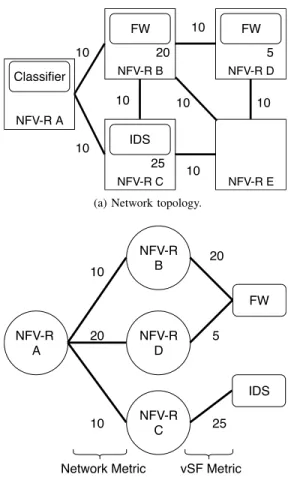
NFV-R A NFV-R D NFV-R C NFV-R B NFV-R E FW FW IDS Classifier 10 10 10 10 10 10 10 20 5 25
(a) Network topology.
NFV-R A NFV-R C NFV-R B NFV-R D FW IDS 10 20 10 20 5 25
Network Metric vSF Metric
(b) Service plane topology seen at the NFV-R A.
Fig. 2: Each NFV-R builds its service plane topology (example at Node A on Fig. (b)) with the Network costs and vSF costs so as to compute the next hop(s).
that in Figure 1b, since the same address is announced but no adjacency is made between the vSF (the two Firewall instances in our example), the flows that use a link to reach a service function (drawn as boxes) have to use the same link to go out of it. However, note as well that this link is only virtual, since it is the representation of the vSF instance in the IGP, but in reality, is running directly on an NFV-R.
Augmenting the IGP modularly allows to fully benefit from what is already done at the network layer routing. Anycast addressing leverages IGP information sharing to build the augmented topology. Based on this topology a routing decision maps vSF type to the appropriate next(s) NFV-R(s) based on network and instances metric. Finally, the IGP gives us robust IP connectivity between NFV-Rs to steer flows through the correct set of instances. Note that the IGP prevents from flow remapping in case of link failure. Indeed, once the IGP has converged, connectivity to NFV-Rs is restored without any change in cached routing decisions. Moreover, NFV-Rs can be incrementally deployed in domains where they coexist with classical routers. Indeed, since services are announced as IP addresses, classical routers will advertise them to their neighbor. Based on this raw IP topology, an NFV-R is able to reconstitute the service plane topology.
is responsible to configure high level policies on the NFV-R. As for any IGP, these policies are common to all the nodes. They allow controlling the decision-making at each NFV-R. Such policies include flow classification rules, to map traffic to the needed service chain. They also concern routing decisions since all NFV-Rs must share the same routing objectives. Based on the service plane topology, the NFV-Rs can use any path computation algorithm (e.g., shortest path first), to choose which instance of the next vSF of the chain the flow will go through. Additionally, high level policies can define as well how to compute vSFs’ IGP costs, stating which data to use and the function to translate such data in a cost.
Our approach can rely on network encapsulation to convey the necessary information so to drive flows through the as-sociated service chain. This information can be used to take routing decision at the source or at every NFV-R processing the flow (hop-by-hop). This header should include (i) part or all of the service chain identified at the classification step at the ingress of the network, (ii) the next service step in this chain, and iii) a consistent flow identifier to cache the routing decision. For instance, in the example in Figure 1, the NFV-R that hosts the IDS instance must have a mean to know that a packet belonging to a specific flow has been assigned to the service chain IDS + F W , that the next service to apply is F W , and which of the F W instances it actually has to go through.
In the rest of the paper, we focus on hop-by-hop routing, although source routing is applicable too, and take OSPF as an example for the IGP. Fig. 2 illustrates how a service plane topology is constructed from a network topology. In this approach, every NFV-R computes the shortest path to every vSF type in terms of network and vSF cost and map each vSF type to the associated NFV-R forwarding address. This mapping can be easily computed by running Dijkstra algorithm on the topology presented in Fig. 2b and by getting the last hop before the destination in the shortest path to a vSF type. The cost that each NFV-R associates to the announced prefix, i.e. the IGP cost to reach such an address, represents the vSF state and can be based on a plethora of parameters [16], [17] (e.g., its available capacities, its load etc.). Note however that the used metrics (link and service) should be in the same order of magnitude. More importantly, they have to be additive, so to guarantee loop-free convergence even when considering multiple constraints [18], [19]. Using OSPF, NFV-Rs, as classic routers, already compute routing table to get aggregated network costs to NFV-Rs. Thus, the algorithm to find the route to the next vSF instance has to run only on a graph of depth 2 and add very low compute overhead to the routing system. In Section VI, we discuss the cost overhead induced by a hop-by-hop routing decision compared to centrally computed end-to-end path.
IV. NFV-R ARCHITECTURE
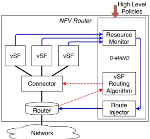
In this section, we describe the architecture of a NFV-R and the design its main modules. An NFV-R, as illustrated in Figure 3, is composed of a normal IP router providing
NFV Router Connector Network vSF vSF vSF Resource Monitor Route Injector vSF Routing Algorithm High Level Policies Router D-MANO
Fig. 3: NFV-R architecture. Doted arrows illustrate vSF routing control flow. Solid arrows show how vSFs state is monitored, transformed in a cost, which is then injected in the IGP.
network connectivity, a connector, which attaches the router to the different vSF instances, the vSFs themselves, providing the services, and a Distributed MANagement and Orchestra-tion (D-MANO) component, which allows local autonomous management of the node.
Router: The router connects our system to the network and participates in this network IGP. It is directly connected to the connector external interface and announces this interface’s IP address on the IGP, making the connector forwarding address reachable. The router only conveys packet based on their destination IP and is unaware of the service chaining encapsulation. It exposes a control interface used by the D-MANO to inject or remove vSF anycast addresses, announcing the services available on the node and the associated costs. This control interface is also used to get the IGP topology to build the service plane topology.
Connector: The connector acts as a proxy for the vSF and allows dispatching traffic to them. It exposes an external interface whose IP address is used as forwarding address in anycast announce. It enforces chaining decisions as follows. It forwards incoming packets to the intended vSF instance, based on the encapsulation header. Once the packets have been processed, the vSF forwards them back to the connector, which enforces a forwarding decision toward the next vSF instance location (i.e., its connector) according to the service topol-ogy. These forwarding decisions are cached in the connector, indexed by a hash computed using flow-related information.
The connector also exposes a control interface, used by the D-MANO, to populate the service-aware routing table and the mapping between service function and vSF instance unicast address. This information is used by the connector to enforce chaining decisions for outgoing traffic, and locally balance the load among the vSF instances that provide the same service (same prefix).
Names Nodes Edges Demands Type
RF1755 87 322 7527 Rocketfuel inferred RF3967 79 294 6160 Rocketfuel inferred
SYNTH50 50 276 2449 Synthetic
TABLE I: Evaluation dataset.
vSF: vSF instances process service flow packets according to the service they provide. Once a packet has been processed, the vSF instance updates the chaining encapsulation header to point to the next service. Each instance is monitored and managed by the D-MANO.
Distributed MANO: The D-MANO controls and manages the other NFV-R’s components. It is configured with high level policies, which guide its autonomous orchestration decisions. It has three essential control functions (illustrated in Figure 3). The first one consists in monitoring vSF instances, deriving from them vSF costs and the second one in injecting such costs in the IGP, via the router. The third function consists in getting IGP information from the router to build the service plane topology, computing the service-aware routing table and then pushing it in the connector.
V. EVALUATIONMETHODOLOGY
In this section, we describe the methodology we followed to evaluate our proposal. We present the publicly available ISP topologies. We introduce the mathematical formulation of the SFC routing problem we use to compare the chaining decision taken by a holistic centralized orchestrator and the decision taken hop-by-hop (at each next vSF hosting waypoint) by NFV-Rs. Then, we present our implementation of NFV-R and the Grid’5000 testbed [20] we use to emulate and evaluate NFV-R networks.
A. Dataset
We use three ISP topologies that were previously used in [9] and made publicly available [21]. They are summarized on Table I. The first one was synthetically generated, while the two others were inferred in the Rocketfuel project [22]. They include path delays. We use the weights provided with the dataset to configure the IGP link costs. We consider all the nodes as NFV-Rs able to host vSF instances. The dataset also contains demand matrices that we use for service chain demands.
For each experiment, we randomly select 5% of the overall demands to build our service requests (ingress, egress, bitrate), as in [9]. We run two types of scenarios. In scenario 1, all the requests have to be steered through one vSF. Only one type of vSF is present on the network. There are 10 instances of it. In scenario 2, all the requests have to be steered through a vSF of type 1 and then a vSF of type 2. There are 5 instances of each type. In both scenarios, the vSF instances are placed on the nodes that have the highest betweenness centrality, i.e., the nodes traversed by the highest number of IGP shortest paths. Such selection criteria has been shown to be efficient for vSF chaining in centralized approaches [23].
Parameters G Graph representing the network N Set of routers and NFV-Rs
P Subset of N representing the NFV-Rs E Set of links
R Set of SFC requests to serve V Set of available vSF types
lv,p Boolean. An instance of vSF v is located on NFV-R p
cn1,n2 IGP link cost between node s1 and node s2 ur Number of vSFs in the service chain of the request r
ir Ingress node for the request r
er Egress node for the request r
br Bandwidth used by the request r
vi
r ithvSF type asked by the request r
Decision variables
xi,vr Boolean representing where vri is placed
yl,n1,n2
r Float representing flow from vSF vl−1r to vSF vlr
TABLE II: Notations.
B. Analytical comparison between centralized and distributed chaining decisions
In this subsection, we describe the models for the central-ized and the distributed chaining schemes.
1) SFC routing model parameters: We formulate as an Integer Linear Program (ILP) model the SFC routing problem. The notations for the variables and parameters are summarized in Table II. The network is represented by a directed graph G = (N , E), where N is the set of nodes (classic routers and NFV-Rs) and E is the set of edges. P represents the subset of nodes that are actually NFV-Rs. The set of different vSF types is depicted by V. On our topology, vSF instances placement is represented by the input lv,p. We describe a SFC request with the following parameters: ir the ingress node, er the egress node, br the bitrate, Vr= (vr1, vr2, ..., vrlr) the set of requested vSF types.
2) Cost function: As explained in Section III, we consider two types of costs in our system: the vSF cost and the network link cost. We model these costs as follows.
vSF Cost: The vSF cost represents the cost to use vSF instances. It is proportional to the requests’ bandwidth, which may be expressed in packet or Bytes per second.
Cp=X p∈P X r∈R ur X i=1 brxi,pr (1)
Link Cost: The link cost corresponds to the network cost defined on the IGP. cn1,n2is the IGP static link cost of the link
n1, n2. Note that in our model the link cost is proportional to the used bandwidth to take into account shortest paths.
Cl= X (n1,n2)∈E X r∈R ur+1 X l=1 yl,n1,n2 r c n1,n2 (2)
3) Problem formulation: The goal of a centralized orches-trator is to find a path for each request, which minimizes both network and processing costs, while steering traffic through the correct sequence of vSFs. The problem is formulated as follows:
Objective:
Subject to:
∀p ∈ P, ∀r ∈ R, ∀i ∈ [1 : ur], xi,pr ≤ lp,vi
r (4) ∀r ∈ R, ∀i ∈ [1 : ur], X p∈P xi,pr = 1 (5) ∀r ∈ R, ∀(n1, n2) ∈ E , ∀u ∈ [1 : ur+ 1], yu,n1,n2 r >= 0 (6) ∀r ∈ R, ∀n1∈ N , X n2/(n1,n2)∈E yi,n1,n2 r − X n2/(n1,n2)∈E yi,n2,n1 r = (xi−1,n1 r − xi,nr 1) · br, 2 ≤ i ≤ ur (1 − xi,n1 r ) · br, f or n1= ir, i = 1 (xi,n1 r ) · br, f or n16= ir, i = 1 (xi−1,n1 r − 1) · br, f or n1= er, i = ur+ 1 (xi−1,n1 r ) · br f or n16= er, i = ur+ 1 (7) The objective function aims at minimizing both the vSF cost and the link cost. Equation 4 ensures that requests are only routed to instantiated vSF. Equation 5 ensures that each request uses only 1 vSF instance to process their flow at each step of the chain. Equation 6 ensures that the amount of resource unit on a link is not negative. Equation 7 ensures network flow conservation.
Note that in this model, we do not take into account the capacity of the links or of the vSF instances. We directly use the IGP cost and the vSF cost. We consider that traffic engineering or vSF scaling decision should not be taken at the routing layer.
This formulation models the decision of a central orches-trator to find the overall best paths for each request. We adapt it to also model the distributed hop-by-hop decision taken by NFV-Rs. Indeed, we run the ILP segment by segment: from the ingress nodes to the first vSF instances, then from these vSFs instances to the next ones and so on until the egress nodes. We implemented these ILP formulations with CPLEX Optimization Studio. In Section VI, we compare these two routing schemes.
C. Emulation on Grid5000 testbed
In this subsection, we describe our NFV-R prototype imple-mentation and the testbed environment used to experimentally evaluate our proposal on large emulated network topologies.
1) NFV-Router prototype: In the following paragraph, we detail the we made technical choices to build our NFV-R and describe the implementation of each components presented in Section IV.
We build our implementation on top of the Open Shortest Path First (OSPF) protocol. This IGP is widely used and easily extensible thanks to opaque Link State Advertisements (LSAs). We leverage these opaques to announce information
related to the vSF instances and call them vSF LSA. These LSAs do not trigger SPF computation when received by routers. Thus our solution does not affect the IGP stability. The only overhead induced by flooding vSF LSAs is the additional traffic control. We show in section VI that this overhead is negligible. We convey 3 pieces of data with these LSAs: i) the anycast address of a vSF instance (i.e. the provided service), ii) the associated vSF cost, and iii) the associated forwarding address (i.e., the location of this vSF instance). In our implementation, we choose to use a simple vSF metric: the number of packet per second processed by a vSF instance. We use the Network Service Header (NSH) [13] encapsula-tion format to steer traffic through service funcencapsula-tion chains. We motivate our choice since this standard is explicitly designed for SFC use cases and has been adopted by a plethora of opensource framework [24]–[27]. In NSH, the Service Path Identifier (SPI) field uniquely identifies a set of abstract service functions (i.e., the Service Function Chain), while the Service Index (SI) points to the next function the packet has to be delivered to in the SPI set. NSH also provides extensible metadata fields that we leverage to convey the hash value used to consistently identify a flow along its chain even if a vSF modify the original packet. Such hash value is computed at the classification step with the 5-tuple of the original packet.
We build our NFV-R using Linux and package it as an LXC container [28]. We isolate each of the architectural components using Linux network namespace.
Router: In our implementation, we use FRRouting [29], an open source IP routing protocol suite, to implement our OSPF router. In particular, we use the OSPF API offered by FRRouting to mirror the Link-State Database (LSDB) in the D-MANO and to inject vSF opaque LSAs.
Connector: We implemented the connector logic in P4, a language for programming the dataplane [30]. In our imple-mentation, we add the classification function to the Connector to ease NSH encapsulation. On each NFV-R, the connector is connected to a traffic generator. Based on the traffic matrix, UDP traffic is generated and forwarded to the Connector. The connector then enforces a classification policy: based on the UDP destination port, it encapsulates incoming packet with the associated NSH header, choose the next vSF to reach based on its vSF routing table and forward it to the router. Our P4 code is run on the simple switch target [31]. Its runtime CLI is exposed to the D-MANO to configure the switch (e.g., with classification policy) and populate the vSF routing table at runtime.
vSF: vSFs are implemented as simple socket servers, which parse incoming packets, decrement their NSH SI field, and forward them back to the connector. The focus of our work being on the routing system, we purposely choose simplistic vSFs for the time being. The Python psutil library enables us to monitor the resources used by the vSF processes.
D-MANO: The D-MANO has been implemented in Python. Its main loop runs as follows. First, it polls the resource use of the local vSF instances to build the related costs. The costs are then announced on the network with vSF opaque
LSAs. Second, the D-MANO gets the vSF announces from its mirrored LSDB. With these data, it builds a service view (see Fig. 2b). Based on this topology, it computes the shortest path to every vSF type present on the network, get the associated forwarding address, and update the vSF routing table on the connector.
2) Grid’5000 environment: We deployed emulated topolo-gies of NFV-Rs on the Grid’5000 testbed [20]. Grid’5000 is a large scale and versatile testbed, which provides access to a large amount of resources (12000 CPU cores) distributed on different sites and interconnected by a 10Gb/s WAN. This testbed is highly reconfigurable, which makes it a great tool for experiment-driven research. In our experiments, we use Distem [32], a network emulation tool, to deploy NFV-R LXC on bare-metal servers. For each NFV-R, Distem uses Linux cgroups to allocate 4 vCPUs (i.e., 4 CPU cores) to each NFV-R. Distem connects NFV-R with VXLAN tunnels to emulate the topology links. We run our experiments on a cluster of 48-nodes with the following host main characteristics: Intel Xeon E5-2630L v4 (Broadwell, 1.80GHz, 2 CPUs/node, 10 cores/CPU), 10Gb Ethernet interface. We deployed the topologies and scenarios with these tools.
Traffic is generated at the granularity of an UDP flow. We fix flows arrival rate, duration and packet size. Packet rate of each flow is then accommodated to correspond to the demand’s bandwidth in bits per second. Thus, once the steady state is reached (i.e., when a first flow duration period has elapsed), each demand generates the dataset input bandwidth with k UDP flows, k corresponding to the flow duration divided by the arrival rate, which we set to 50s and 2 flow/s respectively. Even if this uniform traffic distribution is simplistic, it gives a first assessment on our system behavior. In future work, we will use more realistic traffic patterns.
VI. EVALUATION
In this section we evaluate our proposal following the methodology explained in Section V. First, we use our ILP formulations to compare the additional cost and path stretch induced by a distributed decision. Then, we outline the control reactivity induced by a centralized orchestrator compared to a distributed solution. Finally, we evaluate with emulation the dynamics of the system and the additional control traffic overhead.
A. Centralized vs. distributed chaining decisions
First, we compare the overall cost addition and path stretch induced by our distributed hop-by-hop chaining decision. For each combination of topology and scenario, we run 20 experi-ments with different traffic matrices (computed as explained in Section V). In each experiment, we compute with our ILP the cost of each demand and the path length in both the centralized and distributed cases. We then make the ratio of the distributed cost and centralized cost for each demand. We apply the same methodology to compute the path stretch distribution.
Fig. 4 presents the cost ratios. We can observe that with chains of 1 vSF, the median costs are the same for cen-tralized and distributed decisions. For 75% of the demands,
RF1755
1 vSF
RF3967
1 vSF
Synth50
1 vSF
RF1755
2 vSF
RF3967
2 vSF
Synth50
2 vSF
Topology
Scenario
1.0
1.2
1.4
1.6
Cost ratio
Fig. 4: Cost ratio between centralized and distributed chaining decisions for chains with 1 and 2 vSFs.
RF1755
1 vSF
RF3967
1 vSF
Synth50
1 vSF
RF1755
2 vSF
RF3967
2 vSF
Synth50
2 vSF
Topology
Scenario
1.0
1.5
2.0
Path stretch
Fig. 5: Path stretch between centralized and distributed chain-ing decisions for chains with 1 and 2 vSFs.
the cost difference is below 4% on the two largest topolo-gies (RF1755 and RF3957) and below 20% for the smallest topology (Synth50 with 50 nodes). Logically, the cost ratio increases when the number of vSFs per chain increases. The distributed decision scheme still well performs on the two largest topologies. The median goes up to 1.2 for the synthetic topology.
This limited cost increase with the distributed chaining scheme is counter-balanced by the control reactivity. Indeed, while NFV-Rs take routing and chaining decisions almost instantaneously, since they use the augmented IGP, that is the service plane topology, a centralized system will rely on an control node to monitor and take decision.
On each topology, we place the central network orchestrator on the node with the highest betweenness centrality and compute the Round Time Trip (RTT) to every node on the network. This RTT corresponds to the control loop of a central control node, it first gets the data from the network nodes and then enforces a decision on it. Fig 6 shows the control loop latency induced by a centralized orchestration. This overhead can reach 14ms in worst case scenario for inferred topologies and 16ms for the synthetic one. Even if these values can seem small, they are significant for a controller, which applies chaining decision on network appliances forwarding traffic at
rf1755
rf3967
synth50
Topology
2.5
5.0
7.5
10.0
12.5
15.0
RTT to controller (ms)
Fig. 6: Centralized controller reactivity.
linerate. In addition, they have to be compared to the reactivity of the NFV-Rs that is almost instantaneous.
B. Additional control overhead and traffic steering on emu-lated networks
We now present the results of our large-scale experiments. We compare different update period for vSF LSAs and discuss the tradeoff between the network traffic control overhead induced by these LSAs and the network dynamics.
Fig. 7 and Fig. 8 show the additional overhead generated by NFV-Rs with one and two types of vSFs respectively. In both cases, there are at all 10 instances in the network. Logically, when the frequency is low, the overhead is low. We can also observe that it is slightly higher with two vSFs types than with one. Indeed, the routers have to propagate distinctive LSAs.
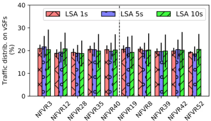
The control overhead has to be discussed with the dynamics of traffic steering. Indeed, a low LSA period results in a less accurate view of the network at routers. Fig. 9 shows the traffic distribution when there is one vSF type on the largest topology. We can see that the load is well distributed on the instances, considering also OSPF weights. When the LSA period increases, the traffic distribution tends to be less stable but remains quite fair. Fig. 10 presents the results when there is two vSF types. The load doubles on the instances as there are five of each type. We can also observe that the spread slightly increases with increase of the LSA period. Finally, we summarize in Table III and Table IV the experiment results for the two other topologies with one and two vSF types respectively. They are conform to the above observations.
Topology RF3967 SYNTH50
LSA Period 1s 5s 10s 1s 5s 10s
Worst NFV-R MeanStd 12.200.27 12.250.78 11.251.68 10.331.80 10.363.57 11.056.01 Best NFV-R Mean 7.70 8.38 8.60 9.80 9.62 7.46
Std 0.59 1.55 2.21 1.74 3.15 4.56
TABLE III: Traffic distribution (%) for 1 vSF chains.
VII. CONCLUSION
In this paper, we have proposed to augment the network routing layer, thus relying on the robustness and scalability of IGPs, to steer traffic into service chains. We have presented
1
5
10
LSA update period (s)
0
500
1000
1500
2000
OSPF additional control traffic
(bytes/s/link)
rf1755
rf3967
synth50
Fig. 7: OSPF overhead induced by NFV-Rs with various LSA update periods for 1 vSF chains.
1
5
10
LSA update period (s)
0
500
1000
1500
2000
OSPF additional control traffic
(bytes/s/link)
rf1755
rf3967
synth50
Fig. 8: OSPF overhead induced by NFV-Rs with various LSA update periods for 2 vSF chains.
NFVR8 NFVR3NFVR42NFVR40NFVR52NFVR39NFVR12NFVR28NFVR19NFVR35
0
5
10
15
20
Traffic distrib. on vSFs
(%)
LSA 1s
LSA 5s
LSA 10s
Fig. 9: Traffic distribution over vSF instances with various LSA update periods for 1 vSF chains on the RF1755 topology.
NFVR3NFVR12NFVR28NFVR35NFVR40NFVR19NFVR8NFVR39NFVR42NFVR52
0
10
20
30
40
Traffic distrib. on vSFs
(%)
LSA 1s
LSA 5s
LSA 10s
Fig. 10: Traffic distribution over vSF instances with various LSA update periods for 2 vSF chains on the RF1755 topology, type 1 vSFs on the left, type 2 vSFs on the right.
Topology RF3967 SYNTH50 LSA Period 1s 5s 10s 1s 5s 10s Worst NFV-R (Type 1 vSF) Mean 22.34 20.99 21.09 23.92 27.08 31.38 Std 2.04 2.75 4.61 2.84 6.30 10.50 Worst NFV-R (Type 2 vSF) Mean 25.71 25.44 25.21 20.10 21.42 20.72 Std 0.27 0.58 0.78 2.38 5.84 9.90 Best NFV-R (Type 1 vSF) Mean 18.82 18.91 18.10 18.84 17.52 14.50 Std 1.48 2.37 2.97 2.67 3.41 5.13 Best NFV-R (Type 2 vSF) Mean 16.46 16.91 17.30 19.92 19.31 19.21 Std 0.70 2.08 2.06 2.32 4.77 8.92
TABLE IV: Traffic distribution (%) for 2 vSF chains.
our solution, described the architecture of our augmented node (called NFV-Router) and built a proof of concept, which can be incrementally deployed on current networks. We have evalu-ated our proposal on ISP topologies and demand matrices. The evaluation shows that NFV Routers’ chaining decisions are close to optimal centralized decisions, while ensuring a quasi instantaneous reactivity. Moreover, our large-scale emulation results show that, with a small control traffic overhead, NFV-Routers smoothly steer traffic through chains.
In future works, we plan to study: (i) if this solution could be applied to external gateway protocol so to provide inter-domain service chaining, (ii) which meaningful metrics could be used for vSF and (iii) to which extent our distributed service plane topology could be leveraged to take distributed vSF provisioning decisions.
REFERENCES
[1] J. Sherry, S. Hasan, C. Scott, A. Krishnamurthy, S. Ratnasamy, and V. Sekar, “Making middleboxes someone else’s problem: Network pro-cessing as a cloud service,” in Proc. of the ACM SIGCOMM Conference, 2012, pp. 13–24.
[2] M. Ghaznavi, N. Shahriar, S. Kamali, R. Ahmed, and R. Boutaba, “Distributed service function chaining,” IEEE Journal on Selected Areas in Communications, vol. 35, no. 11, pp. 2479–2489, 2017.
[3] J. G. Herrera and J. F. Botero, “Resource allocation in NFV: A comprehensive survey,” IEEE Transactions on Network and Service Management, vol. 13, no. 3, pp. 518–532, 2016.
[4] S. Palkar, C. Lan, S. Han et al., “E2: A framework for NFV appli-cations,” in Proc. of the Symposium on Operating Systems Principles (SOSP), 2015, pp. 121–136.
[5] A. Gember-Jacobson, R. Viswanathan, C. Prakash, R. Grandl, J. Khalid, S. Das, and A. Akella, “OpenNF: Enabling innovation in network func-tion control,” in ACM SIGCOMM Computer Communicafunc-tion Review, vol. 44, no. 4, 2014, pp. 163–174.
[6] Y. Zhang, N. Beheshti, L. Beliveau et al., “Steering: A software-defined networking for inline service chaining,” in Proc. of IEEE Network Protocols (ICNP), 2013, pp. 1–10.
[7] S. K. Fayazbakhsh, V. Sekar, M. Yu, and J. C. Mogul, “Flowtags: Enforcing network-wide policies in the presence of dynamic middlebox actions,” in Proc. of the ACM SIGCOMM Workshop on Hot Topics in Software Defined Networking, 2013, pp. 19–24.
[8] A. Gember, A. Krishnamurthy, S. S. John, R. Grandl, X. Gao, A. Anand, T. Benson, A. Akella, and V. Sekar, “Stratos: A network-aware orchestration layer for middleboxes in the cloud,” CoRR, vol. abs/1305.0209, 2013. [Online]. Available: http://arxiv.org/abs/1305.0209 [9] R. Hartert, S. Vissicchio, P. Schaus, O. Bonaventure, C. Filsfils, T. Telkamp, and P. Francois, “A declarative and expressive approach to control forwarding paths in carrier-grade networks,” in ACM SIGCOMM computer communication review, vol. 45, no. 4. ACM, 2015, pp. 15–28. [10] Z. A. Qazi, C.-C. Tu, L. Chiang et al., “SIMPLE-fying middlebox policy enforcement using SDN,” in Proc. of the ACM SIGCOMM, 2013, pp. 27–38.
[11] A. Abdelsalam, F. Clad, C. Filsfils et al., “Implementation of virtual network function chaining through segment routing in a linux-based NFV infrastructure,” in Proc. of the IEEE Conference on Network Softwarization (NetSoft), 2017, pp. 1–5.
[12] P. Zave, R. A. Ferreira, X. K. Zou, M. Morimoto, and J. Rexford, “Dynamic service chaining with dysco,” in Proc. of the Conference of the ACM Special Interest Group on Data Communication, 2017, pp. 57–70.
[13] P. Quinn, U. Elzur, and C. Pignataro, “Network service header (NSH),” Internet Requests for Comments, RFC 8300, 2018.
[14] S. Rajagopalan, D. Williams, H. Jamjoom, and A. Warfield, “Split/merge: System support for elastic execution in virtual middle-boxes,” in Proc. of the USENIX Conference on Networked Systems Design and Implementation (NSDI), 2013, pp. 227–240.
[15] M. Kablan, A. Alsudais, E. Keller, and F. Le, “Stateless network functions: Breaking the tight coupling of state and processing,” in Proc. of the USENIX Conference on Networked Systems Design and Implementation (NSDI), 2017, pp. 97–112.
[16] “nfv-vital.”
[17] P. Naik, D. K. Shaw, and M. Vutukuru, “NFVPerf: Online performance monitoring and bottleneck detection for NFV,” in Proc. of the IEEE Conference on Network Function Virtualization and Software Defined Networks (NFV-SDN), 2016, pp. 154–160.
[18] Z. Wang and J. Crowcroft, “Bandwidth-delay based routing algorithms,” in Proc. of the IEEE Global Telecommunications Conference (GLOBE-COM), vol. 3, 1995, pp. 2129–2133.
[19] J. J. M., “Algorithms for finding paths with multiple constraints,” Networks, vol. 14, no. 1, pp. 95–116.
[20] D. Balouek, C. Amarie et al., “Adding virtualization capabilities to the Grid’5000 testbed,” in Cloud Computing and Services Science, ser. Communications in Computer and Information Science. Springer International Publishing, 2013, vol. 367, pp. 3–20.
[21] “Defo website,” https://sites.uclouvain.be/defo/.
[22] N. Spring, R. Mahajan, and D. Wetherall, “Measuring ISP topologies with rocketfuel,” ACM SIGCOMM Computer Communication Review, vol. 32, no. 4, pp. 133–145, 2002.
[23] N. Tastevin, M. Obadia, and M. Bouet, “A graph approach to placement of service functions chains,” in IFIP/IEEE Symposium on Integrated Network and Service Management (IM), 2017, pp. 134–141.
[24] “fd.io,” https://fd.io/. [25] “Opnfv,” https://opnfv.org.
[26] “Opendaylight,” https://www.opendaylight.org/. [27] “Onos,” https://onosproject.org/.
[28] “Linux container (lxc),” https://linuxcontainers.org/. [29] “Frrouting,” https://frrouting.org/.
[30] P. Bosshart, D. Daly, G. Gibb et al., “P4: Programming protocol-independent packet processors,” ACM SIGCOMM Computer Commu-nication Review, vol. 44, no. 3, pp. 87–95, 2014.
[31] “P4 software switch,” https://github.com/p4lang/behavioral-model. [32] “Distributed systems emulator (distem),” https://distem.gforge.inria.fr/.