HAL Id: hal-00516263
https://hal.archives-ouvertes.fr/hal-00516263
Submitted on 9 Sep 2010
HAL is a multi-disciplinary open access
archive for the deposit and dissemination of
sci-entific research documents, whether they are
pub-lished or not. The documents may come from
teaching and research institutions in France or
abroad, or from public or private research centers.
L’archive ouverte pluridisciplinaire HAL, est
destinée au dépôt et à la diffusion de documents
scientifiques de niveau recherche, publiés ou non,
émanant des établissements d’enseignement et de
recherche français ou étrangers, des laboratoires
publics ou privés.
Measuring the erodibility of soil materials constituting
earth embankments: a key input for dams and levees
safety assessment
J.R. Courivaud, J.J. Fry, S. Bonelli, N. Benahmed, P.L. Regazzoni, D. Marot
To cite this version:
J.R. Courivaud, J.J. Fry, S. Bonelli, N. Benahmed, P.L. Regazzoni, et al.. Measuring the erodibility
of soil materials constituting earth embankments: a key input for dams and levees safety assessment.
Hydro 2009, Lyon, 26-28 octobre 2009, Oct 2009, Lyon, France. 9 p. �hal-00516263�
Measuring the erodibility of soil materials constituting
earth embankments: a key input for dams and levees
safety assessment
J.-R. Courivaud, J.-J. Fry EDF- Hydro Engineering Centre. Savoie Technolac
73373 Le Bourget du Lac Cedex France
S. Bonelli, N. Benahmed
Cemagref - Hydraulics Engineering and Hydrology Research Unit.
3275 route de Cézanne, CS 40061, 13182 Aix-en-Provence Cedex 5 France P.-L. Regazzoni, D. Marot Institut GeM. UMR CNRS 6183. 44600 Saint Nazaire France
Introduction
Ensuring the safety of hydraulic embankment structures, including earth embankment dams, levees and dykes, is a major concern all over the world. Still today, about one to two large dams fail every year and hundreds, probably thousands of dykes, levees and small dams fail every year throughout the world. Embankment hydraulic structures can be subject to three potential failure modes: instability, internal erosion and external erosion. The physical parameters driving instability are the pore pressures inside the embankment and its foundation. This failure mode covers both general slope sliding and instabilities due to seismic loadings. Statistics show that 6% of the failure of large embankment dams are due to that process [1]. Internal erosion can be initiated in the embankment and/or in its foundation by four several types of processes: concentrated leak erosion, backward erosion, contact erosion and suffusion [2]. Concentrated leak erosion and backward erosion can lead to one of the most sudden and dangerous failure mode: piping flow erosion. Statistics show that 46% of the failures of large embankment dams are due to that process [1]. External erosion is due to the detachment of the embankment material by the overtopping flow. Erosion of the upstream toe of dykes and levees can also lead to failures. Statistics show that 48% of the failures of large embankment dams are due to these processes of external erosion [1].
Studies of real cases of embankment dam failures and research works performed in the last two decades on hydraulic embankments erosion both show that (1) breach parameters (such as the breach peak outflow, the final breach length or the breach opening duration) can not be correctly predicted only by geometrical parameters of the embankment and the upstream reservoir and (2) that the erodibility of a soil material can not be directly correlated to usual geotechnical parameters (such as cohesion, dry density or permeability). Taken into account the behaviour of the embankment and foundation material under the flow action, that is called the material erodibility, is now considered essential for safety assessments of that type of structures.
Different experimental devices, called erodimeters, have been developed for studying sediment transport in rivers or earth embankment erosion. Their use is always based on an assumption of an erosion law, which is the relation between the rate of erosion (i.e. quantity of eroded material per time unit per surface unit) and parameters characterizing the flow and the soil material.
Two erodimeters have been selected for the assessment of the erodibility of hydraulic embankment structures. This selection was based on the physical processes these tests are representing and also on their practical
characteristics. These two erodimeters are the Jet Erosion Test (JET) and the Hole Erosion Test (HET). After presenting the physical principles of these two tests and the modelling upon which they are based, their engineering application is illustrated as well as the research needs that remain.
1) Needs of embankment hydraulic structures safety assessment studies
The safety of embankment hydraulic structures (earth embankment dams, dykes, levees) needs to be periodically assessed in order to provide to the owner the knowledge necessary to adapt its plans of maintenance and eventually decide to rehabilitate the structure and/or reinforce the monitoring. The primary objective of the safety assessment studies is to evaluate the level of risk of failure of the embankment by each of the three potential failure modes: instability, internal erosion and external erosion. In some cases, this safety assessment can be completed by a preliminary design of a rehabilitation and/or a monitoring reinforcement if needed.
1.1 Analysis of the risk of failure by instability
The analysis of the risk of failure by instability requires to define four models of the embankment and its foundation:
a geometrical model, that defines the geometry of the embankment generally by 2D vertical cross sections, based on topographic measurements. The main objective of this model is to point out the anomalies in the geometry, i.e. the differences between the design geometry and the actual one that can have an impact on the safety. A geological and hydrogeological model, that defines the nature and geometry of the layers constituting the foundation and the position and fluctuations of the ground water table.
A geotechnical model, that defines the geotechnical parameters that characterize the soil material constituting the embankment and its foundation.
A hydraulic model, that defines the hydraulic characteristics of the soil constituting the embankment and its foundation as well as the hydraulic boundary conditions.
Input data of these analysis are provided from topographic, geophysical and geotechnical surveys. Geotechnical engineers have a long experience of that kind of analysis, for both static and dynamic instabilities. For a large majority of case studies, the conventional tools used for in situ surveys, laboratory tests and numerical modelling are satisfactory.
However, similar conventional tools are not available to perform assessment of failure embankment hydraulic structures by internal or external erosion, that represent 94% of failures of large embankment dams and also the primary risk of failure of small structures.
1.2 Analysis of the risk of failure by overtopping erosion
External erosion by overtopping has been studied both in Europe and in the US during the past fifteen years ([3], [4], [5], [6]). These research efforts have been focused on both numerical modelling and large field or laboratory tests of overtopping erosion and breach development.
From the laboratory and field tests performed at the USDA-ARS Hydraulic Laboratory in Stillwater, Oklahoma, USA [6] and in Norway [7], engineers gained a better comprehension of the physical processes that drive the overtopping erosion process. Studies performed at the USDA-ARS Hydraulic Laboratory were focused on cohesive embankments. They describe the overtopping erosion into four phases, starting by the erosion of the downstream face of the embankment and ending by the breach widening. They have underlined the headcut migration phenomenon and the attack of the embankment soil by plunging jets. They have shown that the soil erodibility is the key soil parameter that drives the erosion dynamics. From the study of this physics, the USDA-ARS Hydraulic Laboratory has developed an experimental device, the Jet Erosion Test (JET) [8], in addition with a numerical modelling of this process, in order to quantify the erodibility of a given soil and predict its erosion when submitted to an overtopping flow.
The Norwegian tests explored different types of materials and zoning: homogeneous clay, homogeneous gravels and zoned embankment with a moraine core and rock fills upstream and downstream. The general physics shown by these tests is in agreement with the one shown by the USDA-ARS tests despite the grain size distribution of the soil materials tested was broader. Results of these tests have been used for numerical model testing by the European IMPACT project [4] and by the ongoing CEATI-DSIG “Erosion of Embankment Dams” project [9].
This CEATI-DSIG project aims to develop next-generation numerical models of embankment dam failure by overtopping taking into account these recent contributions in the physics comprehension.
Before next-generation numerical models are available to the engineers, one must recognize that still today no industrial numerical model able to represent correctly the physical processes of overtopping erosion and providing predictive capabilities is available for engineering studies. However, as it has been shown that soil erodibility plays a key role in the overtopping erosion process ([6], [4], [9]) and an experimental device designed to measure and quantify this erodibility already exists, the analysis of the risk of failure by overtopping can be significantly improved till now by estimating this parameter with the JET.
1.3 Analysis of the risk of failure by internal erosion
Internal erosion can be initiated by four different physical processes [2]: Concentrated leak erosion;
backward erosion; suffusion;
contact erosion.
Safety assessment studies must analyse the risk of initiation of each of these four processes.
Concentrated leak erosion may occur in a crack in an embankment or its foundation or it may occur in a continuous permeable zone containing coarse and/or poorly compacted materials which form an interconnecting void system. The concentration of flow causes erosion of the walls of the crack or interconnected voids.
Backward erosion involves the detachment of soil particles when the seepage exits to a free unfiltered surface. The detached particles are carried away by the seepage flow and the process gradually works its way towards the upstream side of the embankment or its foundation until a continuous pipe is formed.
Suffusion involves selective erosion of fine particles from the matrix of coarser particles (coarse particles are not floating in the fine particles). The fine particles are removed through the voids between the larger particles by seepage flow, leaving behind an intact skeleton formed by the coarser particles.
Contact erosion involves selective erosion of fine particles from the contact with a coarser layer for instance along the contact between silt and gravel sized particles.
These four processes of initiation of internal erosion lead to radically different time scales of the erosion process. Concentrated leak and backward erosion, when they are not stopped by proper filtration, can result in the formation of a tunnel called a “pipe” between the upstream and the downstream faces of the embankment or its foundation. The time scale of that erosion process is typically several hours. Very different is the time scale of suffusion and contact erosion which can be tens of years. It is not known if slow erosion processes, like suffusion or contact erosion can suddenly evolve to a quick erosion process, like concentrated leak erosion or backward erosion.
Taking into account the time scales of these processes, it is crucial to devote significant efforts to the analysis of the risk of failure by piping flow erosion which is the most dangerous type of internal erosion process.
Research efforts led during the ten past years mainly in Australia and France on the piping flow erosion are now able to provide to the engineers a methodological framework including both experimental and numerical tools, that can predict the kinetics of the erosion process for a given embankment hydraulic structure and given hydraulic boundary conditions ([10], [11]). The experimental device designed to characterize the soil erodibility when it is submitted to a piping flow erosion is the Hole Erosion Test (HET). Cemagref at Aix-en-Provence, France, has developed jointly one of these experimental devices and a mechanically justified numerical model of the test. These experimental and numerical tools provide essential input information for the analysis of the risk of failure by piping flow erosion.
2) The Jet Erosion Test
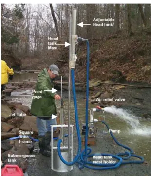
The JET is an erodimeter developed by the USDA-ARS Hydraulic Laboratory, Stillwater, Oklahoma, USA. This test is normalized by the ASTM norm D5852 (2003). It consists in measuring in time the scouring of a soil under a vertical submerged impinging jet. It can be performed both in the field or in laboratory. The apparatus is principally constituted of an adjustable head tank, a jet tube, nozzle, point gage and a jet submergence tank (see Fig. 1).
Fig. 1. Jet Erosion Test performed in situ (picture from USDA-ARS)
Measurements of the scour versus time are made by the operator by mean of the point gage which is in the axis of the impinging jet. The model of interpretation of the JET developed by the USDA-ARS Hydraulic Laboratory assumes that the erosion occurring during the test is principally due to the shear stress applied to the soil near the jet axis (see. Fig. 2). This model is based on the theory of an immerged jet impinging a plane surface.
Fig. 2. Principal of the Jet Erosion Test developed by USDA-ARS and stress distribution around the jet axis
Head Water Surface Original Bed J J J p i e Potential Core Diffused Jet Scoured
Bed Jet Centerline
do Stress Distribution 2 i p o i J J ττττ ==== ττττ for Ji > Jp Where τo = ρ Cf U2
The erosion rate (
•
ε
, rate of the eroded volume of soil in m.s-1) is linked to the shear stress (τ) by the excess stress equation:(
)
>
−
≤
=
• c c D csi
K
si
τ
τ
τ
τ
τ
τ
ε
0
where: cτ
is the critical stress;D
K
is the erodibility coefficient.The model of interpretation of the JET developed by the USDA-ARS Hydraulic Laboratory provides the erodibility parameters
K
D andτ
c.3) The Hole Erosion Test
The HET developed by Cemagref has been designed to test both disturbed or intact soil samples taken in situ from the embankment (see Fig. 3). The test procedure has been carefully defined in order to ensure reproducible tests and to avoid any dependence on the operator. Intrumentation includes pressure probes, a flowmeter and a turbidimeter. The acquisition time step is one second. One test last about three to six hours without taking into account the time for preparing the sample. Sample preparation also follows a precise procedure.
Fig. 3. The Hole Erosion Test device developed by CEMAGREF
The principle of the test is simple: a 3 mm radius pipe is initially sunk into the soil sample, then a flow of water circulates through the conduit in a controlled way in order to start the erosion process. A sample of kaolinite before and after the test is shown on the Fig. 4.
(a) (b) (c) Fig. 4. Hole Erosion Test on a kaolinite sample.
(a) Sample before test (b) Sample after test (c) longitudinal cut of the sample after test
Clean water (in) Sample Water + particles (out)
Pressure in Pressure out
The mechanically justified modelling of that test developed by Cemagref relies on an erosion law, which is the classical excess stress equation:
(
)
>
−
≤
=
• c b c b er c bsi
k
si
m
τ
τ
τ
τ
τ
τ
0
where: •m
is the eroded mass rate in kg.m-2.s-1;b
τ
is the shear stress in Pa;c
τ
is the critical stress in Pa;er
k
is the erosion kinetics coefficient in s.m-1.Once the HET has been performed, the numerical model is used to determine the two parameters of the excess stress equation:
k
erandτ
c. These two essential parameters drive the erosion kinetics.k
eris a key input to quantify the failure time of the embankment. They can range from 1 Pa to about 200 Pa forτ
cand from 10-1 s/m to 10-7 s/m fork
er.The numerical modelling of the HET developed by Cemagref has been validated upon extensive data of HET results performed in different laboratories [12].
Based on that modelling, Cemagref developed simplified relations that predict failure time and peak outflow in case of an hydraulic embankment failure by piping flow erosion [13]
4) Interpretation of erodibility tests results in hydraulic embankment structures safety
assessment studies
Detecting the presence of eventual highly erodible areas inside an embankment or its foundation is an essential objective of the safety assessment studies. Such erodible areas can be underlined by several indices provided by the review of historical data, visual inspections, geophysical and geotechnical surveys. Erosion parameters, KD,
Ker and τc provide a key complementary information to assess the level of erodibility of the suspected weak
areas.
Using their extensive data of HET results, Wan and Fell, from the University of New South Wales, Australia, defined a soil classification according to their erodibility [14]. The erosion celerity is classified from extremely slow to extremely rapid depending on the erosion rate index, Ie (see Fig. 5):
Ie = - log10 Ker
Where Ker (in s . m-1 ) is the erodibility coefficient of the excess stress equation used by the model of
interpretation of the HET.
A similar approach has been conducted with data of JET results by G.J. Hanson of the USDA-ARS Hydraulic Laboratory. In this study, the erosion resistance of the soil is classified from very resistant to very erodible depending on both the erodibility coefficient KD and the critical shear stress τc [15]. One should notice that this
study focused on streambed soils in a loess area. The erodibility of that kind of soils could differ from that of hydraulic embankment structures and this classification could consequently evolve when a similar approach will be applied to embankment structures. The Hanson classification is shown in the Fig. 6.
The evaluation of the erosion parameters with the JET and/or the HET in the frame of hydraulic embankment safety assessment studies provide direct for use information on the level of erodibility of the embankment material that can lead to the following assessments:
- is there a risk that the hydraulic loads lead to overtopping or internal flows with shear stresses larger than the critical shear stress of the embankment material?
- Are there areas in the embankment where the level of erodibility is significantly higher than in the other parts of the structure?
Fig. 9. Wan and Fell classification of soil erodibility
Fig. 6. Hanson classification of soil erodibility
5) Conclusion: recommendations and research needs
As external and internal erosion are the main potential risks of failure of the earthen embankment hydraulic structures, it is essential to characterize the embankment soil erodibility in the frame of safety assessement studies. During the last decade, several erodimeter devices have been developed together with their model of interpretation. The JET and the HET have been used extensively and provide quantified erosion parameters. Both are relatively simple tests and the experimental devices are robust. The erosion parameters determined by these tests allow the engineer to identify weak zones of high erodibility into an embankment, estimate the risk of initiation of erosion for given hydraulic load condition (load condition leading to a given shear stress applied by the flow on the soil) and locate the level of erodibility of the embankment versus other embankment hydraulic structures.
However some unknowns remain inducing research needs. Research work comparing HET et JET results on the same soils prepared in the same conditions shows differences in the erosion parameters that are not presently well understood [16]. These differences could be explained by the different type of effort applied by the flow on the soil in these two tests. The main research need to fill this gap is to develop a unified mechanically justified model of interpretation for these two tests. Another research need is to extend the characterization of soil
Fell guidelines 0 1 2 3 4 5 6 7 1 10 100 1000 E ro s io n r a te i n d e x I e Fell Data
Critical shear stressττττc (Pa)
Moderatly rapid Very rapid Moderatly slow Very slow Extremely slow Extremely rapid
erodibility to coarse soils, including alluvial soils with broad grain size distributions. Both JET and HET tests are presently limited to 3 mm maximum grain sizes.
Despite these gaps to be filled and research needs, JET and HET are presently ready to provide to the community of embankment hydraulic structure owners and engineers essential and valuable information to assess the risk of failure by external or internal erosion. It is recommended to use systematically these tests as soon as the risk of failure of an embankment dam, a dyke or a levee has to be assessed.
References
1. Foster, M and Fell, R. “Assessing embankment dams, filters which do not satisfy design criteria”, J. Geotechnical and Geoenvironmental Engineering, ASCE, Vol. 127, N°.4, May 2001.
2. Fell, R. and Fry, J.-J. “The state of the art of assessing the likelihood of internal erosion of embankment dams, water retaining structures and their foundations”, Internal Erosion of Dams and their Foundations, Robin Fell & Jean-Jacques Fry – editors, Taylor & Francis, 2007.
3. CADAM (Concerted Action for Dam Break Modelling),
www.hrwallingford.co.uk/projects/CADAM
4. IMPACT (Investigation of Extreme Flood Process and Uncertainty), www.samui.co.uk/impact-project
5. FloodSite (Integrated Flood Risk Analysis and Management Methodologies), www.floodsite.net
6. Hanson G.J., Cook K.R., Hunt S.L. “Physical Modelling of Overtopping Erosion and Breach Formation of Cohesive Embankments”, Transactions of the ASAE, Vol. 48(5): 1783-1794, 2005. 7. Lovoll A. “Breach formation in rockfill dams. Results from Norwegian field tests”. Q 86 – R.4. ICOLD
Congress, June 2006.
8. Hanson G.J., Cook K.R. “Procedure to estimate soil erodibility for water management purposes”, ASAE/CSAE International meeting. Paper n° 992133. Toronto, Ontario, Canada. July 19-21, 1999. 9. Wahl T., Hanson G.J., Courivaud J.-R., Morris M.W., Kahawita R., McClenathan J.T., Gee D.M.
“Development of next-generation embankment dam breach models”, USSD Conference, Portland, Oregon, USA. 2008.
10. Wan C.F., Fell R. “Investigation on internal erosion and piping of soils in embankment by Slot Erosion Test and the Hole Erosion Test”, UNICIV Report n° R-412, 2002.
11. Bonelli S., Brivois O., Borghi R., Benahmed N. “On modelling of piping erosion”, Compte Rendus de Mécanique, Vol. 8-9, n°334, p. 555-559. 2006.
12. Bonelli S. and Brivois O. “The scaling law in the hole erosion test with a constant pressure drop”, International Journal for numerical and analytical methods in geomechanics, 2007.
13. Bonelli S., Benahmed N., Philippe P., Bernard A, Grémeaux Y, Nunes G. “Evaluer le temps de rupture d’une digue en remblai érodée par conduit traversant”, Ingénieries n° spécial, p. 85 – 94, 2009. 14. Wan C.F. and Fell R. “Investigation of rate of erosion of soils in embankment dams”, Journal of
Geotechnical and Geoenvironmental Engineering, 130 (4), p. 373-380.
15. Hanson G.J and Simon A. “Erodibility of cohesive streambeds in the loess area of the Midwestern USA”, Hydrological Processes, 15, 23-28. 2001.
16. Regazzoni P.L, Marot D., Courivaud J.R., Hanson G.J., Wahl T. “Soils erodibility: a comparison between the Jet Erosion Test and the Hole Erosion Test”, Inaugural International Conference of the Engineering Mechanics Institute, EM 2008.
The Authors
J.-R. Courivaud graduated from Institut National Polytechnique de Grenoble, is a hydraulic specialist at the Hydro Engineering Centre of EDF, in the Expertise & Development Branch. He is leading the EDF R&D project on prevention of erosion in embankment hydraulic structures and performs engineering studies of safety evaluation for that type of structures. J.-J. Fry. As an engineer with a doctorate in Soil Mechanics, Jean-Jacques FRY has devoted his 28 years of professional activity to this subject and its application to the design and study of earthfill and rockfill dams. He has participated in the studies and construction of most of the earthfill dams dealt with by EDF over the past 20 years, both in France and abroad, and in particular in China, India, Sweden, Chili, Algeria, Gabon, Cameroon, Poland, Bangladesh (dyke protection against floods), and Vietnam. Jean-Jacques FRY actively participates in the development of calculation codes in the fields of stability and dynamic analysis for earthfill dams. Furthermore, as an Expert in Soil Mechanics for the United Nations, he carried out expert consultancy missions in geotechnics for 10 years for the UNDP.
N. Benahmed, MSc, PhD in Geotechnics from National School of Bridges and Roads (ENPC), Paris, France. Research Fellow at Bristol University, United-Kingdom. Currently Research Scientist in Geomecanics at Cemagref, France. Research interests include mechanics and micro mechanics behaviour of geomaterials (in particular the instability and liquefaction of granular materials, creep behaviour and destructuration of clay), erosion process of hydraulics works with a particular emphasis on the development of new experiments to characterize erosion phenomenon.
P.-L. Regazzoni