Electric Field Measurement In Rod-discontinued Plane Air Gaps Using Distributed Capacity Probe
10
0
0
Texte intégral
(2) A. Khechekhouche et al.. J Fundam Appl Sci. 2014, 6(1), 1-10. 2. 1. INTRODUCTION In the field lightning protection several models had been suggested by different authors [1],[2] and [3]. The more studied case is the negative descending strike. In such case, when the steeped leader reaches its critical position, the final jumps occur with a probability overloading to the principal discharge (return strike) characterized by the ascending positive current flow from the earth to the storm cloud, neutralizing the negative charges situated at the basis of this later [3]. The electrogeometrical model considers that the earth is plate and perfectly conducting. In reality the earth could be heterogeneous and constituted with conducting and not conducting parts. For that we had carry out investigations on the attracting zones of an horizontal and vertical lightning conductors situated as well as homogenous or heterogeneous earths [4],[5], [6] and[7]. With regard to Horvath investigation on the lightning protection modelisation [3], we may verify the electrogeometrical model using a laboratory experimental rod-plane air gap arrangement with a lightning conductor (Franklin rod or horizontal conductor). The stepped leader could be represented by the rod electrode under a negative lightning impulse voltage having a level leading to breakdown with 100% probability (U100%). We have found that these zones could be greater than defined by the electrogemetrical model, but could be also lower especially in the case of a lightning discharge occurring in the neighborhood of the interface of different parts of heterogeneous earth [7], [8] and [9]. To explain this fact we have carried out investigation on the influence of earth heterogeneity on the breakdown voltage of rod air gaps [10]. In this paper, we present some results of investigation carried out to measurement the electrical field concerning the discontinuous earth. In a first part we will show the results concerning the electrical breakdown under lightning impulse voltage, and in a second part the results concerning the electric field measurement using a distributed capacity probe.. 2. EXPERIMENTALL SET UP 2.1. CASE OF HOMOGINUOUS EARTH The used arrangement with homogeneous system is made up of a square metallic sheet (Fig.II.1). The high voltage (HV) rod is made up of steel with 4.8mm diameter, and hemispheric end shape. The applied voltage is given by a (-1.2/50µs) lightning impulse generator of 600 kV, 4 kJ. The position of the rod is determined by its height h compared to the earth..
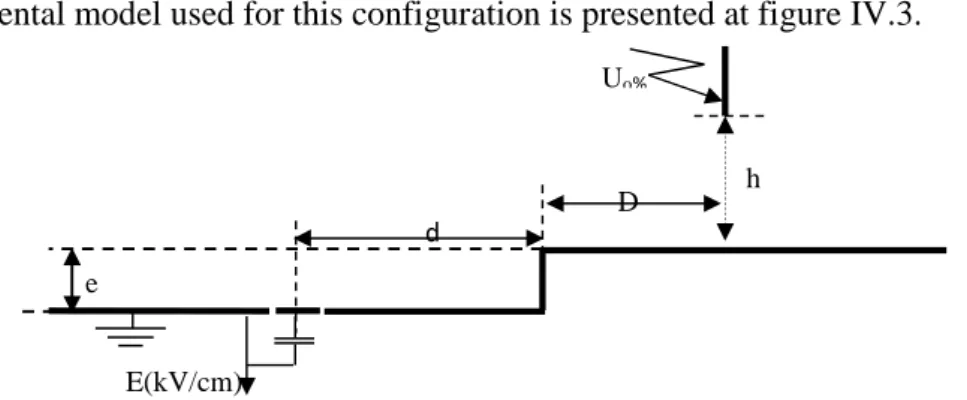
(3) A. Khechekhouche et al.. J Fundam Appl Sci. 2014, 6(1), 1-10. 3. -1.2 / 50s. h. d. Probe. Fig.II.1. Experimental arrangement for electric field measurement with homogenous earth.. 2.2. CASE OF DISCONTINUOUS EARTH The studied earth called “discontinuous earth” is made up of a square metallic sheet with 10 mm thickness and having two different levels of respective surface 1.2×1.2 m2 (Fig.II.2).. Uo%. h D d e E(kV/cm). Fig. II.2. First configuration: Experimental arrangement for electric field measurement discontinuous earth.. The position of the rod is determined by its height (h) compared to the earth and the distance (D) between its axis and the interface. This distance is considered positive when the rod is located above the high and negative part in the other case. The distances h are the same one as in homogeneous system, but the distances d and D are.
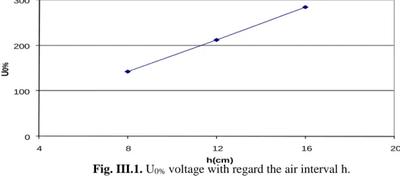
(4) A. Khechekhouche et al.. J Fundam Appl Sci. 2014, 6(1), 1-10. 4. selected so that the tests are carried out for d/h report/ratio and respectively identical D/h for various values of h. The applied voltage level to use is 0.5U0% of the rod-plane corresponding system, at each selected distance h. For a given height h, we as well apply the same applied voltage level for the rod located above the high part as above the low part of the discontinuous plane. Thus it is the same level of applied voltage U0% which is taken into account for a given height h and the corresponding height h+e when the rod is located above the low part of the discontinuous plan.. 3. BREAK OF ROD-PLANE AIR GAP We are interesting to the U0% voltage of disruptive discharge in order to determine the voltage level of selected test equal to 0.5U0%. This applied voltage level allow to avoid the disruptive discharges on the level of the probe because of its sensitivity to the high currents. 300. U0%. 200. 100. 0 4. 8. 12. 16. 20. h(cm). Fig. III.1. U0% voltage with regard the air interval h. . We consider U0% as being the voltage having a probability of discharge equal to 0.1% on the Gausso-arithmetic scale. According to measurements, we note that the applied voltage U0% grows linearly with the increase length of the interval of air h (Fig.III.1). The obtained values of U0% for 8, 12 and 16 cm are also taken as voltage level of tests in the case of the measurements of field for the positions of the stem to the top of the low part of the discontinuous plane; the corresponding distances as far as field will be respectively 18, 22 and 26 cm..
(5) A. Khechekhouche et al.. J Fundam Appl Sci. 2014, 6(1), 1-10. 5. 4. ELECTRIC FIELD 4.1. ELECTRIC FIELD WITH HOMOGINUOUS EARTH In order to obtain a reference for the comparison between the results of the discontinuous system and those of the homogeneous system, we determine initially the distribution of the field in the case of the homogeneous system, according to the position of the probe axis and the height h of the stem under high voltage in the case of the selected voltage level 0.5 U0% (Fig.II.1). With the applied voltage level 0.5U0%, we notice that, the intensity of the electric field tends towards a constant value, as the probe moves away from the rod under voltage starting from a relative position d/h higher or equalizes to 2. When the probe approaches the axis of the rod for r/h lower than 2 the intensity of the field increases slightly and takes a maximum value for d/h ≤1, then decreases in the vicinity of the rod d/h≈0. This last reduction would be due to the space charge phenomenon, whose evaluation by a mathematical model for example, remains still not controlled (Fig.IV.1). For the various positions of the probe (d/h) for the applied voltage level, we notice that the length of the air interval (h) has a great influence on the value of the field on the earth. Indeed, we notice that the intensity of the field increases with the height h. This increase would be due to the applied voltage level to the rod, corresponding to 0,5U0% of the interval. For the intervals h= 18cm, 22cm and 26cm, one same applied voltage U0% as the intervals h=8cm, 12cm and 16cm respectively, which explains the reduction in the field for these great intervals. The increase in the field on the earth could be explained by the presence of the field creates by the space charge in the vicinity of the rod, when the applied voltage level increases (Fig.VI.1).. 4.2. ELECTRIC FIELD WITH DISCONTINUOUS EARTH After the determination of the voltage U0% for the various heights h and the measurement of the electric field of the homogeneous system conducting, we proceed to the study of the various discontinuous earth configurations (Fig.II.2). We distinguish two system requirements rod-plan in the case of the discontinuous earth which were defined according to respective positions of the rod and the probe compared to the two parts of the discontinuous earth.. 4.3. CASE OF THE ROD AT THE TOP OF THE HIGH PART 5. DISCONTINUOUS EARTH.
(6) A. Khechekhouche et al.. J Fundam Appl Sci. 2014, 6(1), 1-10. 6. In this case, we are interested first to two possible configurations corresponding to the two positions of the probe. In the first case the probe is over the high part( Fig.II.2) and the second one the probe is on the low part( Fig.IV.3). In these two cases, the rod is located only above the high part of the plane. 6. 6. 5. 5. 4 h=8cm. 3. h=12cm h=16cm. E(kV/cm). E(kV/cm). 4. h+e=18cm h+e=26cm. 2. 2. 1. 1. 0. h+e=22cm. 3. 0 0. 1. 2. 3. 4. 5. 6. 0. 1. 2. d/h. 3. 4. 5. 6. d/h. Fig.IV.1. Electric field measured on the earth according to the position d/h of the probe (Voltage level U = 0.5U0%) 6. 5. E (kV /cm ). d /h = 5 d /h = 2 d /h = 1. 4. d /h = 0 .5 d /h = 0. 3. 2 4. 8. 12. 16. 20. 24. 28. h (c m ). Fig.IV.1. Electric field measured on the earth according to the h of the probe The obtained results presented in the figures for various relative positions of the D/h rod maintained constant and the positions of the probe d/h varying -5 to +5.. 5.1. FIRST CONFIGURATION: THE PROBE LOCATED ON THE HIGH PART OF 5.1.1. THE DISCONTINUOUS EARTH The experimental model used to study the first configuration is given by the figure II.2. For the applied voltage level 0.5U0% and for the positions of the probe far from the interface (d/h > 2), we notice that the intensity of the field measured on the high part of the discontinuous earth Fig.IV.2. Electric field measured on the earth according to the h of the probe. is practically equal to that corresponding to the case of the system with homogeneous earth (Fig.IV.4). Thus, when the rod moves away from the interface towards the long distances, one.
(7) A. Khechekhouche et al.. J Fundam Appl Sci. 2014, 6(1), 1-10. 7. tightens towards the good conducting rod-plan system of the same length (Fig.IV.4). Near the interface (d/h<2), the results obtained show a kind of discontinuity in the evolution of the electric field. This discontinuity is due to the role of the interface which would have the same effect as a point, transforming the system rod-plan into system rod-rod. This fact explains the abrupt increase in the field above the interface and the reduction in the rigidity of the interval rodinterface and the phenomena of discharge observed in preceding research tasks [03] [04]. Indeed, even for relatively large D/h distances, electric discharges can occur between the rod and the interface and not between the rod and the plan according to the path the shortest correspondent with the height h (Fig.IV.2). We notice that the air interval rod-interface constitutes preferable path for the lines of field. Indeed, the system rod-interface which behaves as a system point-point is less rigid than the system point-plan. This also justifies in our case obtaining sometimes disruptive discharges on the interface, for the low values of the D/h ratio.. 5.2.2. SECOND CONFIGURATION: THE PROBE LOCATED ON THE LOW PART OF 6. THE DISCONTINUOUS EARTH The experimental model used for this configuration is presented at figure IV.3. Uo %. d. D. h. e E(kV/cm). Fig. IV.3. Second configuration: Experimental arrangement for electric field measurement discontinuous earth..
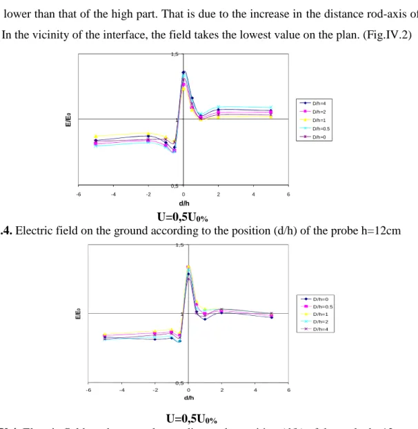
(8) A. Khechekhouche et al.. J Fundam Appl Sci. 2014, 6(1), 1-10. 8. With regard to the field on the low part of the discontinuous earth, the results show that the field intensity is lower than that of the high part. That is due to the increase in the distance rod-axis of the probe. In the vicinity of the interface, the field takes the lowest value on the plan. (Fig.IV.2) 1,5. D/h=4. E/E0. D/h=2. 1. D/h=1 D/h=0.5 D/h=0. 0,5 -6. -4. -2. 0. 2. 4. 6. d/h. U=0,5U0% Fig. IV.4. Electric field on the ground according to the position (d/h) of the probe h=12cm 1,5. D/h=0. E/E0. D/h=0.5. 1. D/h=1 D/h=2 D/h=4. 0,5 -6. -4. -2. 0. 2. 4. 6. d/h. U=0,5U0% Fig.IV.4. Electric field on the ground according to the position (d/h) of the probe h=12cm For the first case where the rod is located above the high part of the plan (Fig IV.5), we notice that report (E/E0) is close to the unit, for the position of the probe far from the interface (d/h>1). On the level of the interface, where the system rod-interface behaves as a system rod-rod which is less rigid than the system rod-plan, the relationship between the two systems takes the value maximum (E/E0=1.25) which corresponds to the value where there is a great probability of having disruptive discharges direct on the interface (Fig. IV.5)..
(9) A. Khechekhouche et al.. J Fundam Appl Sci. 2014, 6(1), 1-10. 9. 7. CONCLUSION Our work is directed towards the experimental determination of the distribution of the field on a discontinuous earth, in order to confirm the influence of the interface. The study developed in our memory highlighted the performances of the probe at capacity distributed in the measurement of the intensity of the electric field on the earth. Using this method of measurement (probe with left again capacity), we determined the distribution of the field on the earth, as well in the case of a homogeneous plan as in that of a discontinuous plan with an interface of constant depth (e). The test results obtained carry out us to make the following observations: - The intensity of the field measured on the level of the interface, is much more significant than that in other points of the earth. This is due to the fact that the interface locally reinforces the electric field, which causes the rise in this one, and the appearance sometimes of discharges on the interface in certain cases (d/h=0 and D/h=0), in spite of the choice of voltage level relatively low tests compared to the voltage level U0% corresponding to 0% of disruptive discharge in the case of the homogeneous earth. - In the vicinity of the interface, we observe a kind of discontinuity in the evolution of the intensity of the electric field. This one, while decreasing, becomes lower than the value obtained in the case of the good conducting homogeneous earth of the same length.. 8. REFERENCES [01]. Golde R. H. « Lightning : T2 », Academic Press, 2ème édition, London,(1981).. [02]. Le Roy G., Gary C., Hutzler B., J. Lacot, C. Dubaton : « Les propriétés diélectriques de. l’air et les très hautes tensions», Ed Eyrolles, Paris, 1984, pp : 92-251. [03]. T. HORVATH : « Computation of Ligthning Protection», Research Studies Press LTD,. England 1991. [04]. A. Boubakeur, J. Ferras : « Négative lightning breakdown of rod-plane air gaps with. heterogeneous earth », 5ème ISH, paper 14-26, Braunschweig ,RFA, 1987. [05]. A. Boubakeur, S. A. A. Boumaza, R. Belaicha, R. Boudissa : « Influence of earth. heterogeneity on negative lightning breakdown of rod-plane air-gaps », 24th ICLP, Birmingham, 1998, pp : 473-477..
(10) A. Khechekhouche et al. [06]. J Fundam Appl Sci. 2014, 6(1), 1-10. 10. A. Rahmani, A.Boubakeur, S. A. A. Boumaza: “The effect of earth conductivity,. homogeneity and heterogeneity on lightning breakdown of short air gaps” 6eme Conférence de la Société Française d’Electrostatique, july 7-9, 2008, Paris (France) pp. 291-296. [07]. A. Rahmani, A. Boubakeur, H. Brouri; “ Model of an horizontal lightning conductor. protection in the case of earth discontinuity” International Symposium on Electromagnetic Compatibility EMC EUROPE 2002, (Sorrento) Italy 2002, pp 267-270 [08]. A. Rahmani, O. Rahmani and A. Boubakeur “Influence of the Position of an Horizontal. Lightning Conductor in the Case of Earth Discontinuity” 4eme Conférence SFE 2004 ISBN: 29505432-4-3 Poitiers, (France) 2004 pp353-357 [09]. A. Rahmani and A. Boubakeur, H. Brouri; “Protection Model of an Horizontal Lightning. conductor in the case of earth discontinuity”, IEEE-PES, paper N° 633; ISBN: 5-93208-034-0, St-Petersburg, Russia, June 2005. [10]. A.Rahmani, A.Boubakeur, S. A. A. Boumaza; "The effect of earth conductivity,. homogeneity and heterogeneity on lightning breakdown of short air gaps". 6eme Conférence de la Société Française d’Electrostatique, SFE2008, july 7-9, 2008, Paris (France) pp. 291-296.. How to cite this. article: Khechekhouche A. Benattous D. Mekhaldi A. Boubakeur A. Electric field measurement in roddiscontinued plane air gaps using distributed capacity probe. J Fundam App Sci. 2014, 6(1), 1-10.
(11)
Figure

Documents relatifs
integrate one photomultiplier output while the other channel was used for the output of the photodiode placed in the laser beam after the cell. Their ratio,
Abstract Head-on collisions between negative and positive streamer discharges have recently been suggested to be responsible for the production of high electric fields leading to
L’archive ouverte pluridisciplinaire HAL, est destinée au dépôt et à la diffusion de documents scientifiques de niveau recherche, publiés ou non, émanant des
This dipolar interaction is on the para-axis (and hence nearly parallel to the long molecular axis) aad, thus, should not be influenc- ed by hindering of rotational
Laboratoire de Spectrometric Physique (CNRS UA-08 and Greco Celphyra), Universit6 Scientifique, Technologique et MBdicale de Grenoble, BP 87, F-38402 Saint-Martin-d'Heres
Abstract : The present paper deals with the influence of insulating barriers on the breakdown and the electric field distribution in the Point –insulating barrier- plane air gap
Figures (11 to 15) show the electric field distribution on the plan electrode for different applied voltages for x position of the barrier, thickness e=1.2mm and a
The experimental data of about 30 spectra for P^La^^Ala specimens at all scattering angles were processed as per the programme taking account into the resolution function (see
