HAL Id: hal-02369105
https://hal.archives-ouvertes.fr/hal-02369105
Submitted on 18 Nov 2019
HAL is a multi-disciplinary open access archive for the deposit and dissemination of sci-entific research documents, whether they are pub-lished or not. The documents may come from teaching and research institutions in France or abroad, or from public or private research centers.
L’archive ouverte pluridisciplinaire HAL, est destinée au dépôt et à la diffusion de documents scientifiques de niveau recherche, publiés ou non, émanant des établissements d’enseignement et de recherche français ou étrangers, des laboratoires publics ou privés.
Application of Lagrangian Energy Approach to
determine the Response of Isotropic Circular Plates
subjected to Air and Underwater Blasts
Ye Pyae Sone Oo, Hervé Le Sourne, Olivier Dorival
To cite this version:
Ye Pyae Sone Oo, Hervé Le Sourne, Olivier Dorival. Application of Lagrangian Energy Approach to determine the Response of Isotropic Circular Plates subjected to Air and Underwater Blasts. 7th International Conference on Marine Structures - MARSTRUCT 2019, May 2019, Dubrovnik, Croatia. �hal-02369105�
1 INTRODUCTION 1.1 State-of-the-art
Both in-air and underwater explosions have long been a major threat for military and civil structures since World War I and II. Such loadings usually involve explosion with very high pressure, causing serious detrimental effects onto the structures. It is thus im-portant to understand the underlying physics concern-ing with these loadconcern-ings to promote the structural safety as well as to propose better and safer designs.
Generally, both in-air and underwater blast load-ing can be viewed as classical impulsive loadload-ing problem in which the initial kinetic energy is dissi-pated as an elastic or plastic strain energy of the struc-ture. Indeed, a considerable body of literature already existed for this kind of problem. Mair (1999) re-viewed and compiled existing analytical, empirical and numerical approaches to determine the sub-merged structural response of underwater explosions. Porfiri & Gupta (2009) presented a comprehensive literature review on noticeable worldwide research efforts in the field of impulsive loading submitted to the marine structures.
Theoretical studies regarding the impulsive re-sponse of steel plates or diaphragms began during the World War II. Taylor (1950), Hudson (1951) and Richardson & Kirkwood (1950) were among the first to conduct experimental and analytical studies on the
dynamic plastic behavior of thin plates. Later, Hop-kins & Prager (1954) studied about dynamic plastic response of simply-supported circular plate subjected to a uniformly distributed load which is brought on suddenly and then removed abruptly after a certain time interval. However, only bending deformation was considered in their analytical model and the cal-culation steps were given depending on the intensity of applied pressure. Symonds & Wierzbicki (1979) obtained exact theoretical membrane solution by ex-amining the impulsively loaded circular plate behav-ior. Jones (1989) also proposed various analytical models for predicting infinitesimal and finite dis-placements of beams, plates and shells with or with-out taking into account the membrane action, trans-verse shear deformation and rotatory inertia effect. Later, this work was extended by Qiu et al. (2004) to apply for underwater shock response of monolithic and sandwich circular plates with clamped boundary condition. In this paper as well, the solutions are split into small and large displacement regime.
So far theoretical solutions from the past decades have been presented. It would however be insufficient without mentioning about the experimental tests. Florence (1966) made experimental study on large impulsive response of simply-supported circular plates and then compared with Wang (1955)’s theo-retical bending solution of impulsively loaded rigid-plastic plates. It was found that disregarding the
Application of Lagrangian Energy Approach to determine the Response
of Isotropic Circular Plates subjected to Air and Underwater Blasts
Y.P. Sone Oo
GeM Institute (UMR CNRS 6183) - Calcul-Meca, Nantes, France
H. Le Sourne
GeM Institute (UMR CNRS 6183) - ICAM Nantes campus, France
O. Dorival
Clément Ader Institute (FRE CNRS 3687) – ICAM Toulouse campus, France
ABSTRACT: This paper presents a simplified analytical formulation that uses Lagrangian Energy Approach to predict air and underwater blast response of air-backed simply-supported circular steel plates. Triangular and exponential pressure profiles are considered for air and underwater blast loading respectively. Calculation of the response is divided into two stages. In the first stage, maximum impulsive velocity is determined by assum-ing that the plate has negligible deformation and then by usassum-ing the conservation of linear momentum for air blast and Taylor’s one-dimensional analytical model for underwater blast. In the second stage of calculation, elastic deformation is obtained by applying the initial conditions determined from the first stage, also taking into account the rotatory inertia and water-added inertia effect. The obtained analytical solutions are tested with various plate aspect ratios as well as various loading levels and the results are compared with those from non-linear finite element explicit simulations. It is found that the proposed formulations correlate well with the finite element results giving only 5–20% discrepancy provided that the plate deflections are supposed to remain small compared to its thickness. Finally, the advantages and limitations of the present method are discussed.
membrane forces could seriously overestimate the fi-nal permanent deflection. A recent experimental and analytical study about the response of metallic circu-lar plates subjected to air blast loading can be seen in Gharababaei et al. (2010). It compares the clamped plate responses using various analytical formulations available in the literature.
Coming back to the underwater explosion, Cole (1948) systematically presented about the underwater explosion and its related physical effects. Compila-tion of some of the earliest research works can be found through three volumes of ‘‘Underwater Explo-sion Research’’ issued by the office of Naval Re-search in 1950. Taylor (1941) proposed a one-dimen-sional fluid-structure interaction (FSI) model when a free-standing rigid plate with an infinite length is im-pacted by a plane shock wave. The finding of this pa-per has been proved expa-perimentally by Deshpande et al. (2006) several decades later. Liu & Young (2008) also extended Taylor’s air-backed model into water-backed FSI model. Rajendran (2001) performed ex-perimental tests to investigate linear elastic shock re-sponse of circular and rectangular steel plates. Strain distributions across the specimen were analyzed and compared with the semi-analytical results and good agreement was achieved. A recent analytical study of cylindrical shell-shock interaction can be found in Brochard et al. (2018) which is an extension of string-on-plastic foundation model originally proposed by Hoo Fatt (1992).
According to Felippa (1980), a structure sub-merged in an infinite acoustic medium needs to sat-isfy the three-dimensional scalar wave equation and the associated FSI effect could be expressed by the exact formulation of Kirchhoff’s Retarded Potential Formula (RPF). However, direct application of RPF to transient response calculations could be computa-tionally expensive due to the need to store a vast amount of historic data when solving coupled motion equations numerically for each time step. This limita-tion is especially obvious when the time steps were to increase. For these reasons, approximate FSI models such as Doubly Asymptotic Approximation (DAA) model developed by Geers (1978) are applied in the field of FSI modelling. The occurrence of cavitation, see Schiffer et al. (2012), and the time evolution of water-added inertia mass also adds more complexities to the study of underwater explosion.
Nowadays, together with the advancement in com-putation power, it becomes possible to study the FSI problem using advanced numerical code such as Un-derwater Shock Analysis (USA) code. The main ad-vantage of this method is that the governing equations are expressed in terms of wet surface variables only and thus, it is not necessary to explicitly model the surrounding fluid. Due to its robustness and relative accuracy, USA code has been incorporated with var-ious commercial finite element codes such as LS-DYNA, NASTRAN, etc. The application of USA
code in shipbuilding can be found in DeRuntz Jr. (1989) and Le Sourne et al. (2003).
1.2 Motivation & Objectives
Even though the application of numerical methods such as LS-DYNA/USA mentioned above seems promising, it is still prohibited in the preliminary de-sign stages due to its complicated modelling steps and expensive computation time. In this regard, analytical solutions become very useful since they could not only provide a wide variety of design choices in a short amount of time but also give more physical in-sights to the problem studied.
Indeed, the objective of this paper is to propose an analytical solution when isotropic circular plates are subjected to air and underwater blasts. The plate is considered as an air-backed plate with simply-sup-ported boundary condition at the edge. Both bending and mid-plane stretching are considered, also taking into account the rotatory inertia and water-added in-ertia effects. The displacements are assumed to be small compared to the plate thickness and the material stress-strain relationship obeys Hooke’s law. Strain rate effect and failure are not considered in this anal-ysis. The obtained analytical solutions are then com-pared with the results of non-linear finite element ex-plicit code LS-DYNA. It is worth mentioning that the finding of this research will be utilized in the future investigation of dynamic behavior of submerged composite plates when subjected to underwater ex-plosion with or without considering the post-damage response by making the same assumption on small displacements presented in this paper.
2 EXPLOSIVE LOADING 2.1 Air-blast loading
Assume that a circular steel plate having radius 𝑎, thickness ℎ𝑠 and density 𝜌𝑠 is loaded by uniformly
distributed pressure pulse which has triangular profile as follows: 𝑃(𝑡) = { 𝑃0(1 − 𝑡 𝜏) 0 ≤ 𝑡 ≤ 𝜏 0 𝑡 ≥ 𝜏 (1) where P0 is the peak pressure; and τ is the decay time
of the shock wave.
The pressure loading in Equation 1 is used to cal-culate the impulse which will be transmitted to the plate as: 𝐼 = ∫ 𝑃0(1 − 𝑡 𝜏) 𝑑𝑡 𝜏 0 = 1 2𝑃0𝜏 (2)
Taking the conservation of linear momentum at 𝑡 = 0 gives the following initial impulsive velocity: 𝑣𝑖𝑎 = 𝑃0𝜏
where the superscript ‘a’ is used to distinguish the air blast loading from water blast loading.
2.2 Underwater-blast loading
The pressure submitted to the plate due to underwater explosion can be considered as near-field or far-field depending on the stand-off distance. The treatment on the compressibility of water and other important physical parameters can vary for near-field and far-field explosions. For the present analysis, it is as-sumed that the plate is sufficiently far enough from the explosive charge so that a plane shock assumption can be considered. Then, the pressure loading which acts on the target can be split into two phases. In phase I, early-time approximation is considered and the im-pulsive velocity is derived based on the procedures given in Cole (1948) and Taylor (1941). In phase II, long-time approximation is considered. Simplified RPF expression for circular plate is applied, assuming that there is no more incident pressure and the water-added inertia arises during plate deceleration.
2.2.1 Pressure loading in Phase I
Now suppose that a circular steel plate with radius 𝑎, thickness ℎ𝑠 and density 𝜌𝑠 is in contact with water of density 𝜌𝑤 on one side and air on the other side. It is
then loaded by a planar exponentially decaying pres-sure pulse having a peak prespres-sure P0, decay time τ and
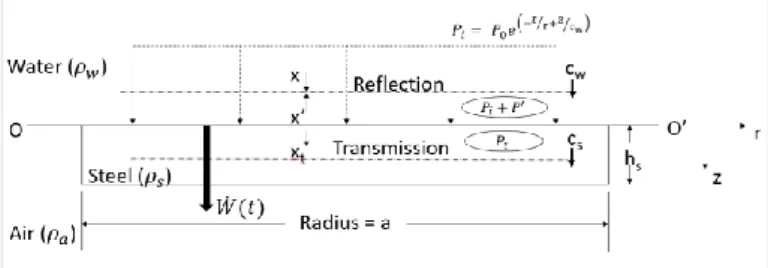
traveling at sonic speed 𝑐𝑤 in water towards the plate as shown in Figure 1. The one-dimensional incident pressure wave 𝑃𝑖 at any arbitrary time 𝑡 and at any distance 𝑧 from the fluid-structure boundary OO’ can be written as:
𝑃𝑖(𝑡) = 𝑃0𝑒(−𝑡/𝜏 + 𝑧/𝑐𝑤) 0 ≤ 𝑡 ≤ 𝜏 (4) Note that polar coordinate (r, θ and z) system is used. The origin of the coordinate is taken at the boundary OO’ and at the centre of the plate. The z-axis is positive for downward direction which is also the same direction for the incident wave.
The peak pressure P0 and decay time τ involved in
Equation 4 can be determined by using the principle of similarity. The principle of similarity states that the pressure and other properties of the shock wave will be the same if the scales of length and time are varied by the same scale factor. Using this principle and the property of TNT explosive, the peak pressure and de-cay constant can be given as a function of explosive mass W in kg and stand-off distance R in m as: 𝑃0 = 52.117 × 10⁶(𝑊1/3 𝑅 ) 1.18 (Nm-2) (5) 𝜏 = 0.09 × 𝑊1/3(𝑊1/3 𝑅 ) −0.185 (ms) (6)
Figure 1. Pressure and particle velocity fields at the boundary As shown in Figure 1, the problem is treated as a 1D problem in which only the transverse displace-ments are considered. Henceforth, the tangential components of the velocity for both particles and the plate are assumed to vanish. The particle velocities for incident, reflected and transmitted wave in the transverse direction are denoted as 𝑥, 𝑥′ and 𝑥𝑡 re-spectively and the plate velocity as 𝑊̇. Note that the plate in this case is assumed to behave like a free-standing plate with negligible amount of deformation until it reaches the maximum impulsive velocity 𝑣𝑖𝑤. Upon arrival of the pressure wave at OO’, part of the incident pressure is reflected back into the fluid while the other part is transmitted into the plate de-pending on the mechanical impedance of the plate’s material. For steel, the mechanical impedance can be expressed as:
𝑍𝑠 = 𝜌𝑠𝑐𝑠 (7)
where 𝑐𝑠 = √
𝐸(1−𝜈)
𝜌(1+𝜈)(1−2𝜈) is the sonic speed in steel.
Let us say the incident pressure at the interface (z = 0) is:
𝑃𝑖 = 𝑃0𝑒−𝑡/𝜏 (8)
The reflected pressure can be described as:
𝑃′ = 𝑃0𝜑(𝑡) (9)
where 𝜑(𝑡) is a temporal function to be determined. Note that 𝜑(𝑡) will decay with time and is actually a component of the reflection and radiated waves due to the transverse movement of the plate 𝑊̇(𝑡). The transmitted pressure can be written as a function of incident pressure according to Cole (1948):
𝑃𝑡= 2𝜌𝑠𝑐𝑠
𝜌𝑠𝑐𝑠+𝜌𝑤𝑐𝑤𝑃𝑖 (10)
By taking the velocity continuity at the fluid-struc-ture interface OO’ and by assuming pressure and par-ticle velocities for sufficiently small disturbances as has been done by Cole (1948), the following equation for 𝜑 can be derived:
𝜑 = 1
𝑃0(𝜇𝑃0𝑒
−𝑡/𝜏− 𝜌
𝑤𝑐𝑤𝑊̇) (11)
where 𝜇 =𝜌𝑠𝑐𝑠−𝜌𝑤𝑐𝑤
𝜌𝑠𝑐𝑠+𝜌𝑤𝑐𝑤 is the reflection parameter. In
the case of rigid boundary, 𝜌𝑤𝑐𝑤 ≪ 𝜌𝑠𝑐𝑠 so that the reflection parameter 𝜇 ≈ 1.
By substituting Equation 11 in Equation 9 and then using Equation 8, the total pressure for phase I can be expressed as:
𝑃(𝑡)𝐼 = (1 + 𝜇)𝑃0𝑒−𝑡/𝜏− 𝜌𝑤𝑐𝑤𝑊̇ (12)
Now by considering the plate initial kinetic energy and the external pressure loading from Equation 12, the following equation of motion can be obtained: 𝜌𝑠ℎ𝑠𝑊̈ + 𝜌𝑤𝑐𝑤𝑊̇ = (1 + 𝜇)𝑃0𝑒−𝑡/𝜏 (13)
The solution of Equation 13 has already been given by Taylor (1941) and the plate will reach the maxi-mum impulsive velocity:
𝑣𝑖𝑤 = (1+𝜇)𝜉𝑃0𝜏
𝜌𝑠ℎ𝑠 (14)
at corresponding cavitation inception time as: 𝑡𝑐𝑤 = 𝜏 𝑙𝑛𝜓 𝜓−1 (15) where 𝜉 = 𝜓− 𝜓 𝜓−1; and 𝜓 =𝜌𝑤𝑐𝑤𝜏
𝜌𝑠ℎ𝑠 . Here again, the
su-perscript letter ‘w’ is introduced to differentiate the water-blast parameters from the air-blast ones. 2.2.2 Pressure loading in Phase II
As discussed above, the deformation of the plate is supposed to commence in the second phase of the re-sponse. By assuming that the incident pressure field vanishes and the associated plate deceleration pro-duces the water-added inertia mass, the approximate form of Kirchhoff RPF for circular plate will take the following: 𝑃(𝑡)𝐼𝐼 ≈ −𝜌𝑤 2𝜋∫ ∫ 𝜕𝑤̇ 𝜕𝑡 𝑎 0 𝑑𝑟𝑑𝜃 2𝜋 0 (16)
In applying Equation 16 to the assumed deformed shape, it should be aware that the added mass will evolve over time starting from 𝑡𝑐𝑤 until the plate
reaches the maximum deformation. The additional impulse caused by the added mass pressure is given as:
𝐼𝑎𝑑𝑑 = ∫ 𝑃(𝑡)𝐼𝐼𝑑𝑡 𝑇𝑚𝑎𝑥
𝑡𝑐𝑤 (17)
where 𝑇𝑚𝑎𝑥 = the time required for the plate to reach maximum deformation.
Considering this effect in the derivation makes the equations non-linear and thus, equivalent parameter 𝐶∗ is introduced in this paper. By assuming 𝑡
𝑐𝑤 ≪ 1,
the equivalent parameter 𝐶∗ can be expressed as a lin-ear function of the ratio ℎ/𝑎 of the circular plate as: 𝐶∗ = 𝐼𝑎𝑑𝑑
𝑃(𝑡)𝐼𝐼𝑇
𝑚𝑎𝑥 ≈ 𝐾𝑎 ℎ
𝑎 (18)
where 𝐾𝑎 = approximation factor for added mass for 0 ≤ 𝐾𝑎 ≤ 𝑎/ℎ. The constant 𝐾𝑎 also depends on the type of plate geometry. In this paper, 𝐾𝑎 is taken as 9
which is obtained by fitting the numerical results us-ing various h/a ratios of circular plates and various applied impulses. Nevertheless, it is clear that this ap-proximation factor is valid only for circular plates and such method to account for water inertia effects needs to be improved in the future.
3 ANALYTICAL FORMULATION 3.1 Problem formulation
The same circular plate from the previous section is considered. To calculate the plate deformation, as-sume that the plate’s transverse displacement is sepa-rable into temporal and spatial variables as:
𝑤(𝑟, 𝑡) = 𝑊(𝑡) (1 −𝑟2
𝑎2) 0 ≤ 𝑟 ≤ 𝑎 (19)
where 𝑊(𝑡) is the maximum deflection at the plate center; 𝑟 the radial coordinates; and a the radius of the plate.Note that the above equation is in consistence with the hypothesis of the parabolic axisymmetric de-formation profile of circular plates under impulsive loads. Equation 19 also satisfies simply-supported boundary condition requirement at 𝑟 = 𝑎 and 𝑟 = 0.
Moreover, the following assumptions are further imposed.
• In-plane displacements are negligible com-pared to the transverse displacement:
|𝑢|, |𝑣| ≪ |𝑤|
• The problem is axisymmetric (no θ term is considered in Eq. 19)
• The loading is uniform pressure pulse distrib-uted all over the plate or impulsive velocity • Radial and circumferential strains are the only
significant terms while:
𝜀𝑧𝑧 ≈ 𝜀𝑟𝑧≈ 𝜀𝜃𝑧 ≈ 𝜀𝑟𝜃 ≈ 0
• Mid-plain strain is derived by using Cauchy strain expression for circular plate and then by expanding into Taylor series and keeping only the first two terms as:
𝜀𝑟 = √1 + ( 𝜕𝑤 𝜕𝑟) 2 − 1 ≈1 2( 𝜕𝑤 𝜕𝑟) 2 (20) • The curvature has the following relationship:
𝜅𝑟 = −𝜕2𝑤 𝜕𝑟2 𝜅𝜃 = − 1 𝑟 𝜕𝑤 𝜕𝑟 (21)
• The plate is assumed to be made with isotropic materials. Then, the flexural rigidity D can be given as:
𝐷 = 𝐸ℎ3
12(1−𝜈2) (22)
where E and v are Young modulus and Pois-son’s ratio of the material respectively. • The stress-strain relations obey Hooke’s law:
[𝜎𝜎𝑟 𝜃] = 𝐸 1−𝜈2[ 1 𝜈 𝜈 1] [ 𝜀𝑟+ 𝑧𝜅𝑟 𝑧𝜅𝜃 ] (23)
The above assumptions lead to the following strain energy for mid-plane radial stretching as:
𝑈𝑠 =1 2∫ ∫ ∫ [𝜎𝑟 1 2( 𝜕𝑤 𝜕𝑟) 2 ] 𝑎 0 2𝜋 0 𝑟𝑑𝑟𝑑𝜃𝑑𝑧 ℎ/2 −ℎ/2 (24)
and the general bending strain energy as follows:
𝑈𝑏 = ∫ ∫ 𝐷 2[( 𝜕2𝑤 𝜕𝑟2 + 1 𝑟 𝜕𝑤 𝜕𝑟) 2 − 2(1 − 𝑎 0 2𝜋 0 𝜈)𝜕2𝑤 𝜕𝑟2( 1 𝑟 𝜕𝑤 𝜕𝑟)] 𝑟𝑑𝑟𝑑𝜃 (25)
Using Equations 19-25 will yield the following non-linear strain energy expression in which the first term corresponds to stretching strain energy and the second term corresponds to bending strain energy: 𝑈 = 2𝜋ℎ𝐸 3(1−𝜈2)( 𝑊2 𝑎 ) 2 + 4𝜋𝐷(1 + 𝜈) (𝑊 𝑎) 2 (26) Similarly, the kinetic energy T is also derived us-ing the followus-ing general expression:
𝑇 = 1 2∫ ∫ ∫ 𝜌(𝑢̇ 2+ 𝑣̇2 + 𝑤̇2) ℎ/2 −ℎ/2 𝑎 0 2𝜋 0 𝑑𝑧𝑟𝑑𝑟𝑑𝜃 (27)
Solving Equation 27 will give the following equa-tion: 𝑇 = [𝜋𝜌ℎ3 12 + 𝜋𝑎2𝜌ℎ 6 ] 𝑊̇ 2 (28)
Finally, Equations 27 and 28 are solved in general Lagrangian Equation: 𝑑 𝑑𝑡( 𝜕𝐿 𝜕𝑞̇) − ( 𝜕𝐿 𝜕𝑞) = 𝑄 (29)
where 𝐿 = 𝑇 − 𝑈; 𝑞 is the generalized coordinate; and 𝑄 the non-conservative force due to external load. In the present case, the generalized coordinate is the central deflection 𝑊(𝑡) and its velocity 𝑊̇(𝑡).
Solving of Equations 26-29 gives the following general expression of equation of motion:
𝐴1𝑊̈(𝑡) + 𝐴2𝑊(𝑡)3+ 𝐴3𝑊(𝑡) = 0 (30)
where 𝐴1, 𝐴2 and 𝐴3 are constants that depend on the blast loading type and will be determined in the fol-lowing sub-sections.
3.2 Air-blast response
Air-blast problem is treated as initial value problem by giving the initial condition of 𝑊 and 𝑊̇ at 𝑡 = 0. The initial condition for plate velocity 𝑊̇ can be de-rived by equating the initial kinetic energy into Equa-tion 28. At 𝑡 = 0, 𝑇 = 1 2𝜌ℎ𝜋𝑎 2𝑣 𝑖2 = [ 𝜋𝜌ℎ3 12 + 𝜋𝑎2𝜌ℎ 6 ] 𝑊̇(0) 2 (31)
By solving Equation 31, the initial condition for plate velocity 𝑊̇(0) is obtained. Now the initial con-ditions are:
𝑊(0) = 0 𝑊̇(0) = √3𝑣𝑖 (32)
where 𝑣𝑖 should be determined from Equation 3. The constants 𝐴1, 𝐴2 and 𝐴3 are determined as:
𝐴1 = 𝜋𝜌ℎ3 6 + 𝜋𝑎2𝜌ℎ 3 𝐴2 = 8𝜋ℎ𝐸 3𝑎2(1−𝜈2) (33) 𝐴3 =8𝜋𝐷(1+𝜈) 𝑎2
Note that the first term of 𝐴1 refers to rotatory in-ertia effect and the second term the mass inin-ertia
effect; 𝐴2 denotes the non-linear membrane stiffness;
and 𝐴3 represents the bending stiffness.
Now substituting Equation 33 into Equation 30 and using Equation 32 as initial condition, the result-ing equation of motion can be solved numerically.
3.3 Underwater-blast response
Underwater blast response has the same form of equa-tion of moequa-tion (Eq. 30), however, water-added mass must be taken into account. As already explained in section 2.2.2, the additional pressure caused by water-added inertia will be determined by using Equation 16. Taking into account the equivalent parameter 𝐶∗
to approximate the temporal evolution of water-added mass, the pressure loading in Phase II can be given as: 𝑃(𝑡)𝐼𝐼 ≈ −2
3𝐶 ∗𝜌
𝑤𝑎𝑊̈ (34)
Equation 34 can be used to derive external non-conservative force term 𝑄 from Equation 29 as: 𝑄 = ∫ ∫ [−23𝐶∗𝜌 𝑤𝑎𝑊̈] 𝑎 0 2𝜋 0 𝑟𝑑𝑟𝑑𝜃 (35)
Taking into account Equation 35 in Equation 30 and applying Equation 32 as an initial condition, the constants 𝐴1, 𝐴2 and 𝐴3 can be derived. The constants 𝐴2 and 𝐴3 are the same as described in Equation 33
while the constant term 𝐴1 becomes: 𝐴1 = 𝜋𝜌ℎ3 6 + 𝜋𝑎2𝜌ℎ 3 + 2 3𝐶 ∗𝜌 𝑤𝜋𝑎3 (36)
Again, the resulting equation of motion can be solved numerically. Note that the initial velocity 𝑣𝑖 in Equation 32 should use 𝑣𝑖𝑤 from Equation 14 for un-derwater blast.
4 NUMERICAL ANALYSIS
Numerical simulations are performed by using the non-linear finite element explicit code LS-DYNA. Detailed modelling steps will be given depending on the type of loading in the next sections. The material properties are given in Table 1 in which three h/a ra-tios are considered, keeping the same areal mass, i.e., the same thickness for each h/a ratios.
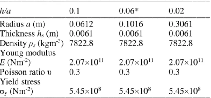
Table 1. Characteristics of the material
________________________________________________ h/a 0.1 0.06* 0.02 ________________________________________________ Radius a (m) 0.0612 0.1016 0.3061 Thickness hs (m) 0.0061 0.0061 0.0061 Density ρs (kgm-3) 7822.8 7822.8 7822.8 Young modulus E (Nm-2) 2.07×10¹¹ 2.07×10¹¹ 2.07×10¹¹ Poisson ratio υ 0.3 0.3 0.3 Yield stress σy (Nm-2) 5.45×10⁸ 5.45×10⁸ 5.45×10⁸ ________________________________________________ * Taken from the paper of Florence (1966)
4.1 Air-blast response
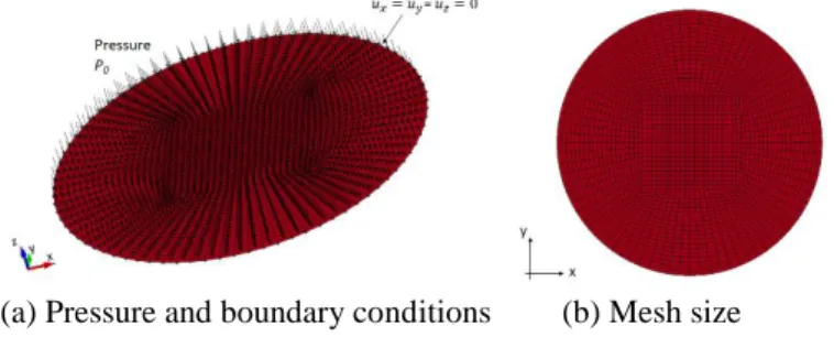
For air-blast loading, the pressure boundary condition is prescribed directly onto the 2D finite element plate. A typical finite element model for ℎ/𝑎 = 0.06 is shown in Figure 2. The mesh adapted for different h/a ratios of the circular plate is between 3 – 7 mm. This mesh size has been ensured to be sufficiently fine enough to capture the correct deformation amplitude as well as the participating mode shapes. The peak pressure used are only between 1 – 10 MPa to make sure that the plate deformations remain small com-pared to the plate thickness and the material response is still within the elastic limit. The decay time of 0.05ms is applied for all pressure loading levels. The plate is modeled using *MAT_PIECEWISE_LINEAR _PLASTICITY LS-DYNA card based on the properties
given in Table 1 without considering the strain rate effect. Shell elements with Belytschko-Tsay formula-tion are used. Five integraformula-tion points are considered throughout the thickness. Simply-supported bound-ary condition is achieved by restraining the displace-ments at the edges but allowing for the rotations.
(a) Pressure and boundary conditions (b) Mesh size Figure 2. Typical finite element model for air-blast simulation
4.2 Underwater-blast response
The FE model for the underwater-blast contains two parts: the fluid part and the structure part. The former is modeled using material ACOUSTIC with acoustic solid element formulation (ELFORM 8) in LS-DYNA. The latter is modeled using *MAT _PIECE-WISE_LINEAR_PLASTICITY with Belytschko-Lin-Tsay shell element formulation. Strain rate and hy-drostatic pressure effects are ignored in the analysis too.
The length of the fluid column is considered 0.25 m. The mesh size of the fluid element is 1 mm in the thickness direction (negative z-direction). The fluid mesh in the x-y plane is used the same as the circular plate mesh in the x-y plane. The mesh size of the cir-cular plate for the underwater-blast is the same as the mesh size used in the air-blast loading model of the plate, i.e., between 3 – 7 mm for the corresponding
h/a ratio. Note that the selection of the mesh size and
the fluid column length have been confirmed by run-ning a number of simulations using only one column of fluid and structural elements. It was found that since only 1D plane shock wave is considered, the as-pect ratio of the fluid element has no effect on the
solutions. Also, the choice of the fluid column length ensures that no returning waves from the boundary influences the plate deformation process. The nodes of the structure and fluid are merged together so that the fluid-structure coupling is automatically treated in LS-DYNA. The lateral surface of the fluid elements is constrained in x and y directions to make sure that 1D wave propagation is properly simulated. The pres-sure loading that ranges from 1 – 10 MPa with 0.081 ms decay time is prescribed as a load boundary at one end of the fluid model and at the other end, the circu-lar plate model is attached by using simply-supported boundary conditions (see Fig. 3). Cavitation is con-sidered in the analysis by defining the pressure cut-off so that when the pressure becomes negative, it will be forced to zero. Numerical damping (BETA = 0.25) is applied on the acoustic fluid element. The conse-quence of this is having a slightly less peak pressure value at the plate. However, analyzing the pressure results and impulse at the nearest element to the plate shows that the results are in accordance with the transferred impulse value provided by Taylor’s FSI formulation at the early-time response. To study the influence of FSI effect, numerical simulations are also performed by using only the impulsive velocity given by Taylor’s FSI model (Eq. 14).
Figure 3. Typical finite element model for underwater-blast sim-ulation
5 RESULTS & DISCUSSION 5.1 Air-blast response
The central deflection-time history for the air-blast loading with h/a ratio of 0.1 and peak pressure 5 MPa is shown in Figure 4. It can be seen that analytical so-lution predicts quite well the maximum deformation with 10% discrepancy. However, it is observed that the FEA solutions contain higher order vibration modes and the final result is the combination of all modal shapes whereas the analytical solution only gives the result of first order mode shape. This leads to the analytical results to have a different peak
response time (about 30% discrepancy) as compared with LS-DYNA. Another limitation of the current model is the assumption on the transverse deformed profile which is supposed to have the same defor-mation mode shape for every time step. This is not true in reality since there is a propagation of a shear wave that starts from the boundary and travels to-wards the plate center and then the deformation con-tinues. The current model simply ignores this wave propagation step for simplicity of the solution, know-ing that the initial velocity field will not have exactly the same mode shape assumed in this paper. This may cause the kinetic energy transmitted to the plate to be slightly different than what has been predicted in the analytical model.
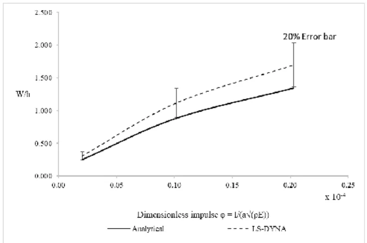
The central deflection-thickness ratio of the plate is compared against different levels of dimensionless impulses 𝜙 in Figures 5 – 7 for different h/a ratios. In general, it can be said that the discrepancy increases as the h/a ratio decreases. For each h/a ratio, the ana-lytical results underestimate about 10–20% less cen-tral-deflection compared to LS-DYNA. However, the response of h/a = 0.02 are in fact no longer small dis-placement solutions and clearly the response is no longer linear due to the occurrence of slight yielding and to the fact that membrane mode deformation be-comes predominant.
Figure 4. Central deflection-time history for air-blast (h/a = 0.1, P0 = 5 MPa,τ = 0.05 ms)
Figure 5. Plots of central deflection-thickness ratio for different impulses of air-blast loading (h/a = 0.1)
Figure 6. Plots of central deflection-thickness ratio for different impulses of air-blast loading (h/a = 0.06)
Figure 7. Plots of central deflection-thickness ratio for different impulses of air-blast loading (h/a = 0.02)
5.2 Underwater-blast response
The central deflection-time history for underwater-blast loading using a peak pressure of 10 MPa is shown in Figure 8. It can be seen that the current an-alytical result predicts well in terms of the peak re-sponse amplitude as well as the peak rere-sponse time. However, the influence of higher order vibration modes and the modal sum results could be clearly seen in the FEA/LS-DYNA results.
Figure 8. Central deflection-time history for underwater-blast (h/a = 0.06, P0 = 10 MPa, τ = 0.081 ms)
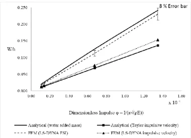
Figure 9. Plots of central deflection-thickness ratio for different impulses of underwater-blast loading (h/a = 0.1)
Figure 10. Plots of central deflection-thickness ratio for different impulses of underwater-blast loading (h/a = 0.06)
Figure 11. Plots of central deflection-thickness ratio for different impulses of underwater-blast loading (h/a = 0.02)
The plots of central deflection-thickness ratio for different levels of dimensionless impulses 𝜙 are shown in Figures 9 – 11, each representing a different
h/a ratio. In order to highlight the significance of
wa-ter-added mass in the second phase of the loading, the analytical results with or without considering the wa-ter-added mass effect, i.e., the constant A1 with or
without the water-added inertia term 2/3 𝐶∗𝜌𝑤𝜋𝑎3.
For better comparison, the finite element results using only the Taylor’s impulsive velocity without explic-itly modelling the fluid model are also included. Note that all of the model compared have the same areal mass by keeping the same thickness and mass density. It can be observed that the current analytical model correlates well with the finite element results with FSI effect, only showing a discrepancy range of 5–8%. It can be found that the results without considering wa-ter-added mass effect could lead to significant under-estimation of the response especially for high h/a ra-tio. The results of finite element model and the analytical one show a similar trend with air-blast model when the water-added mass effects are disre-garded. Here, it should be noticed that the proposed equivalent correction factor C* compensates well the time-evolution of the water-added mass function.
6 CONCLUSION & FUTURE WORKS
In this paper, a simplified analytical model is pro-posed using Lagrangian Energy Approach to derive the equation of motions when the air-backed simply-supported isotropic circular plates are subjected to air-blast and underwater-blast loadings. The calcula-tion steps are divided into two stages. In stage I, the plate is assumed to have negligible amount of defor-mation and then the initial impulsive velocities are derived depending on the type of loading. For air-blast loading, the corresponding impulsive velocity is derived by using the conservation of linear momen-tum whereas for underwater-blast, it is obtained based on Taylor’s 1D FSI model. Then, in stage II, the plate deformation is supposed to commence and the water-added mass inertia increases overtime due to plate de-celeration and collapse of the cavitation zone. The im-pulsive velocity determined from the first stage is used as an initial condition for the second stage. The cavitation near the structure is supposed to occur at the end of the first stage and water inertia forces ap-pear in the second stage. To compensate the time-lapse between the two stages, an equivalent parameter
C* is introduced depending on the plate h/a ratio.
Both air-blast and underwater-blast responses are given for various aspect ratios as well as various im-pulses. The same calculations are performed using non-linear finite element software LS-DYNA. Com-parison of the results from both approaches shows that there is a discrepancy of 10-20% for air-blast and 5-8% for underwater-blast. For an analytical formu-lation, this seems a pretty promising approach.
Of course, there are a few drawbacks too. For ex-ample, the higher order vibration modes are not con-sidered in the present model. In fact, the results shown by FEM is the sum of all modal participation of dif-ferent mode shapes. Another limitation is that the de-formation profile is supposed to remain constant for
all time steps which is not true in reality. There is a propagation of flexural wave front that emanates from the plate boundary and then travels towards the center of the plate. The bending and shear deformations are developed behind its front and thus, this effect must be taken into account in order to accurately model the correct deformed shape for all time histories. Also, for underwater-blast, the equivalent parameter C* is
given as a function of the plate h/a ratio using the co-efficient Ka to compensate for an abrupt transition
from the first to the second stage. However, no rigor-ous justifications have been given regarding the emer-gence of the coefficient Ka nor C*. Moreover, the
ef-fect of hydrostatics pressure, strain rate and geometrical change as well as large deformation ef-fects are ignored in the present analytical approach.
In the future, the approach will be extended to cou-ple with Doubly Asymptotic Approximation model of Geers (1978) for better modelling of pressure loading. The extension of the present approach for different geometries, a square plate for instance, will be carried out. Then, finally, it is the objective of the authors to apply the same approach on submerged marine com-posite plates to investigate their dynamic responses with or without considering the post-damaged behav-ior.
7 ACKNOWLEDGMENT
This research work has been conducted with the fi-nancial support of DGA-DGE. The authors would also like to thank Calcul-Meca and Multiplast com-panies for their technical support.
8 REFERENCES
Brochard, K., Le Sourne, H., and Barras, G. 2018. Extension of the string-on-foundation method to study the shockwave re-sponse of an immersed cylinder. International Journal of
Im-pact Engineering, 117(May 2017):138–152.
Cole, R. H. 1948. Underwater explosions. Princeton University Press, Princeton.
DeRuntz Jr., J. A. (1989). The underwater shock analysis code and its applications. In Proceedings of the 60th Shock and
Vibration Symposium (pp. 89–107).
Deshpande, V., Heaver, A., and Fleck, N. 2006. An underwater shock simulator. In Proceedings of the Royal Society A, num-ber 462, pages 1021–1041, Cambridge, UK.
Felippa, C. A. 1980. A family of early-time approximations for fluid-structure interaction. Journal of Applied Mechanics,
47, 703–708.
Florence, A. L. 1966. Circular plate under a uniformly distrib-uted impulse. International Journal of Solids and Structures,
2(601), 37–47.
Geers, T. L. 1978. Doubly asymptotic approximations for tran-sient motions of submerged structures. The Journal of the
Acoustical Society of America, 64:1500–1508.
Gharababaei, H., Darvizeh, A., & Darvizeh, M. 2010. Analytical and experimental studies for deformation of circular plates subjected to blast loading. Journal of Mechanical Science
and Technology, 24(9), 1855–1864.
Hoo Fatt, M. S. 1992. Deformation and rupture of cylindrical
shels under dynamic loading. Massachusetts Institute of
Technology.
Hopkins, H. G., & Prager, W. (1954). On the dynamics of plastic circular plates. Journal of Applied Mathematics and Physics,
5, 317–330.
Hudson, G.E., 1951. A theory of the dynamic plastic defor-mation of a thin diaphragm. Journal of Applied Physics. Vol. 22, No. 1.
Jones, N., 1989. Structural Impact. Cambridge University Press, Cambridge, UK.
Le Sourne, H., County, N., Besnier, F., Kammerer, C., & Lega-vre, H. (2003). LS-DYNA Applications in Shipbuilding. 4th
European LS-DYNA Users Conference, 1–16.
Liu, Z. and Young, Y. L. 2008. Transient response of submerged plates subject to underwater shock loading: An Analytical Perspective. Journal of Applied Mechanics - Transactions of
the ASME 75.
Mair, H. U. 1999. Benchmarks for submerged structure response to underwater explosions. Shock and Vibration, 6(4):169– 181.
Office of Naval Research 1950. Underwater Explosion
Re-search: a compendium of British and American reports, Vol.
I, II, III. Dept. of the Navy, Washington, D.C.
Porfiri, M. and Gupta, N. 2009. A review of research on impul-sive loading of marine composites. Major Accomplishments
in Composite Materials and Sandwich Structures: An
An-thology of ONR Sponsored Research: 169–194.
Qiu, X., Deshpande, V. S., & Fleck, N. A. 2004. Dynamic re-sponse of a clamped circular sandwich plate subject to shock loading. Journal of Applied Mechanics, 71(September), 637–645. https://doi.org/10.1115/1.1778416.
Rajendran, R., & Narasimhan, K. 2001. Linear elastic shock re-sponse of plane plates subjected to underwater explosion.
In-ternational Journal of Impact Engineering, 493–506.
Richardson, J.M., and Kirkwood, J.G., 1950. Theory of the plas-tic deformation of thin plates by underwater explosions.
Un-derwater Explosion Research, Vol. III, The Damage Pro-cess: 107-121, Office of Naval Research, Dept. of the Navy,
Washington, D.C.
Schiffer, A., Tagarielli, V., Petrinic, N., and Cocks, A. 2012. The response of rigid plates to deepwater blast: analytical models and finite element predictions. Journal of Applied
Mechan-ics, 79.
Symonds, P.S., and Wierzbicki, T. 1979. Membrane mode solu-tions for impulsively loaded circular plates. Journal of
Ap-plied Mechanics, 46(1), 58-64.
Taylor, G. 1941. The pressure and impulse of submarine explo-sion waves on plates. In The Scientific Papers of G. I. Taylor,
Vol. III, pages 287–303. Cambridge University Press,
Cam-bridge, UK.
Taylor, G. I., 1950. The distortion under pressure of a diaphragm which is clamped along its edge and stressed beyond the elas-tic limit. Underwater Explosion Research, Vol. III, The
Damage Process: 107-121, Office of Naval Research, Dept.
of the Navy, Washington, D.C.
Wang, A. 1955. The permanent deflection of a plastic plate un-der blast loading. Journal of Applied Mechanics, 22, 375– 376.