HAL Id: hal-01913423
https://hal.archives-ouvertes.fr/hal-01913423
Submitted on 6 Nov 2018HAL is a multi-disciplinary open access archive for the deposit and dissemination of sci-entific research documents, whether they are pub-lished or not. The documents may come from teaching and research institutions in France or abroad, or from public or private research centers.
L’archive ouverte pluridisciplinaire HAL, est destinée au dépôt et à la diffusion de documents scientifiques de niveau recherche, publiés ou non, émanant des établissements d’enseignement et de recherche français ou étrangers, des laboratoires publics ou privés.
Titanium Holes
Victor Achard, Alain Daidié, Manuel Paredes, Clément Chirol
To cite this version:
Victor Achard, Alain Daidié, Manuel Paredes, Clément Chirol. Optimization of the Cold Expansion Process for Titanium Holes . Advanced Engineering Materials, Wiley-VCH Verlag, 2017, 19 (6), pp.1500626 1-13. �10.1002/adem.201500626�. �hal-01913423�
DOI: 10.1002/adem.1
Optimization of the Cold Expansion Process for Titanium Holes
By Alain Daidie, Manuel Paredes, Clément Chirol and Victor Achard*,
[*] Victor Achard. Corresponding-Author, Prof. Dr. Alain Daidie, Prof. Dr. Manuel Paredes
Université de Toulouse, INSA/ICA (ICA, FRE CNRS 3687), 135 avenue de Rangueil, 31077 Toulouse Cedex 04, France.
E-mail: {victor.achard, alain.daidie, manuel.paredes}@insa-toulouse.fr, [email protected]
Clément Chirol Airbus Operations S.A.S. 316 route de Bayonne 31060 Toulouse Cedex 09
E-mail: [email protected]
Cold expansion of metallic holes is widely used in the aerospace industry as an efficient industrial process for improving the fatigue performance of mechanical assemblies. To increase the efficiency of the process, it is worth considering the possibility of carrying out the expansion twice in succession in the same hole. This paper discusses the consequences of such an operation on a single titanium hole through a numerical and experimental study. More precisely, dedicated finite element modeling of the cold expansion process is developed in order to simulate cases where the expansion is carried out twice: in the same direction and in opposite directions. The residual fields generated are analyzed and the results compared with experimental results. Furthermore, in this study, we propose to assess a new methodology for measuring the intensity of the compressive residual stresses generated at the hole edge. Specifically, we use the incremental hole drilling technique to characterize the expanded holes, with or without a reaming operation of the cold worked hole. Results show that double expansion has a very positive impact on the homogeneity of the compressive fields generated as long as the direction of expansion is properly selected to guarantee the efficiency of the process.
1. Introduction
Aeronautical structures consist of large numbers of riveted or bolted sub-assemblies that require the presence of fastening holes. These sections are often critical in the design and act as major sources of stress concentration where fatigue damage starts.[1] This study focuses on
optimizing the fatigue performance of bolted joints using hole cold expansion. Cold expansion involves the generation of compressive residual stress fields close to the hole edge. The material is thus subjected to compressive and tensile residual stresses that are in overall equilibrium, the compressive stresses generally being balanced by a tensile field away from the hole.[2] To be optimal, radial expansion of the hole should induce circumferential stresses
close to the compressive limit at which the material yields. They thus compensate for the mean value of future tensile fatigue loading and reduce the criticality of these joints. Today, the cold expansion process is used almost exclusively for aluminum holes.
However, optimization of the primary structure of aircraft inevitably leads to the use of titanium alloys. As a result, the number of parts and assemblies made from this material is observed to be increasing exponentially in modern aircraft. As they are very expensive and used in critical areas where loading levels are high, it would be highly desirable to provide processes and tools to improve their fatigue performance. In the aeronautical industry, Ti-6Al-4V alloys are found in the great majority of titanium structural applications and are therefore considered in this study. In the literature, few studies describe the implementation of expansion processes for hard alloys. No precise analysis was made of the response of hard metals subjected to expansion and only studies of specific cases can be found, whereas generic processes designed for the expansion of holes in aluminium alloys were considered. In addition, it is difficult to quantify the fatigue gains obtained in these studies as the various configurations tested involved many parameters influencing fatigue behaviour. However, the previous studies that exist have demonstrated their effectiveness, in particular for titanium
alloys where fourfold increases may be observed in the lifespan of cold expanded holes.
[3,4,5,6,7]
Among the existing processes designed to generate extensive and controllable residual stress fields at the edge of the hole while minimizing damage to the hole surface, split sleeve cold expansion remains the most widely used in industry for aluminum applications.[6,8,9] This
process greatly improves the fatigue performance of the hole. For example, it is commonly noted that the lifespan of a hole that has been cold expanded using the split sleeve process is three to ten times that of an “as drilled” hole in aluminum alloys such as 2024 T351. [10,11]
From a technological point of view, this process can basically be divided into six key steps. First of all, after dimensional checking of the original hole, a pre-lubricated split sleeve is placed on an oversized tapered mandrel, which is connected to the hydraulic actuator. The split sleeve is slid along the maximum diameter of the mandrel and positioned on the minimum diameter so that the tooling can be inserted from one side of the hole. The actuator is subsequently triggered and the mandrel is pulled through the sleeve and the hole, performing the expansion. In the split sleeve process, the sleeve is then removed from its housing. Here, a pre-lubricated sleeve is useful to reduce the axial effort involved in pulling the mandrel and to protect the contact surface. Finally, the hole is reamed to its functional diameter and checked. It is then ready to receive a fastener, for example. The theoretical expansion ratio applied (IE) is defined by relation (1).
= ∅ ∅ ∅ (1)
Where the tooling diameter corresponds to the maximum diameter of the mandrel and sleeve assembly and the initial diameter is the one measured after initial drilling of the specimens. Despite the numerous advantages of this method, e.g. its rapidity of execution, the low cost involved and the high reliability achieved, a study of the residual field generated by expansion reveals significant heterogeneity of the circumferential stress in the thickness of the hole
treated as the one-sidedness of the expansion application induces major axial loads and causes significant side effects. Unfortunately, it also turns out that this circumferential component is responsible for the moderation of stress concentration existing in a loaded drilled plate. More precisely, this heterogeneity is mainly characterized by a decrease in the residual circumferential stresses at the side where the mandrel enters. These poorly expanded areas may reduce the efficiency of the process, the areas exerting the least compression being the most vulnerable. This phenomenon is generally identified and quantified using numerical studies, which are numerous in the literature concerning the split sleeve expansion process.
[12,13] Numerical methods such as finite element modeling appear to be good tools for
predicting the response of the material and particularly the residual fields generated (stress, strain), on condition that the modeling strategies are sound. The modeling choices must be clearly selected in order to simulate highly non-linear behaviors such as high plastic flows and high strain rates. In the case of hard alloys, we found only three numerical studies in the literature. [5,14,8].
This heterogeneity of stresses in the thickness of the hole can be linked theoretically to a reduced fatigue benefit provided by cold expansion. Given the high service loads supported by titanium aerospace components, even a small decrease in the intensity of the compressive stress can lead to significant reductions of lifespan. Considering titanium alloy, the combination of low modulus and high elastic strength is likely to aggravate the phenomenon of reduction of stresses at the mandrel entrance. Thus, in order to achieve even greater benefits, it appears interesting to find ways to improve the homogeneity of these compressive fields while considering the industrial advantages of the split sleeve process. In this study, a simple, low cost methodology is evaluated, which is intended to achieve two successive expansions of the same hole, before its final reaming to the functional diameter. The hope is that the radial expansion of titanium holes will thus be optimized. This kind of methodology has already been studied in cold expansion of aluminum holes, where a study is particularly
noteworthy.[14] These authors were able to show the beneficial effect of double expansion in
opposite directions using conical pins. On the other hand, other studies have shown the benefit of multiple cold expansions on the stress fields generated to be variable.[16,17,18]
In the field of expansion, the characterization of stress fields is a very complex challenge. According to our experience, the stress fields and the areas affected by cold expansion are undetectable by micrograph and microstructural analysis. The stress fields are not “visible” within the material and are the result of a series of balancing/unbalancing effects of the residual stress and strain fields in the material. Furthermore, machining of the parts may involve additional residual fields that can significantly affect those generated by cold expansion. The main objective is to ascertain the distribution and intensity of hoop stresses from the edge of the expanded hole and determine the potential improvement in the fatigue strength of the hole. Validation of predictive models of the residual fields is also very important and can enable fatigue models to be validated for cold expanded holes. Today there is a real need to develop a dedicated method for the study of cold expanded holes. This interest is shared by both the scientific and industrial communities. The main objectives are to limit the amount of expensive fatigue testing (that guarantees and quantifies the effectiveness of a process), to test numerous experimental configurations (new materials, new geometries) and environments (measurement of the relaxation during fatigue, after exposure to temperature or after reaming), and finally to reach a precise characterization of the expanded holes in terms of the stress fields generated. On the other hand, these methodologies can be used to assess the effectiveness of a cold expansion process and think about the best methodologies for extending the process to hard metals, as proposed in this study.
We can distinguish among the measuring methods according to whether they are non-destructive, destructive or semi-destructive (that do not imply the destruction or significant alteration of the structure where the stress is measured). It appears that these methods are interesting for the measurement of the deformation in the material, stress being a
mathematical concept that should be deduced from these measurements. In the elastic domain, the values given by the deformation tensor can be connected with the internal stress tensor via the generalized Hooke’s law. It is important to note that the destructive and semi-destructive methods measure the through-thickness stress/strain values, while the non-destructive methods provide information on the state of the residual fields at the surface or at shallow depth (few µm). Therefore, except for neutron diffraction technology or ultrasonic scanning, they cannot account for the stresses prevailing in the material at depths sufficient to eliminate surface effects that are not representative of the overall behavior of the hole. In addition, in some alloys, X-ray methods are highly dispersive because they are very dependent on the orientation of the grain. On the other hand, optical methods are very useful to describe the distribution of strain fields in the plane of the part to be studied. One study, in particular, showed the capacity, in terms of results and feasibility, of the stereo-correlation hole edge for stamping and expansion. [19,20] Other studies have used Speckle or Moiré interferometry, or
photoelasticimetry.[21,22] One last original methodology proposed by consists of setting up an
expanded grid around the area to measure deformations in the plane of the expanded hole and thus work back to the stress undergone by the periphery of the expanded bore through continuum mechanics.[23]
In other circumstances, destructive methods may be of interest. We first identified the “contour” method. This method aims to achieve residual stresses in one direction. First, the section is cut and the residual stresses are released. The surface profile is measured accurately and the 3D residual profile is finally translated into a two-dimensional stress state through finite element software.[24] In view of the high complexity of the remaining fields after
expansion (in plane and out of plane), a precise reconstruction of the "released" face seems complex. Another technique called the “curvature method” or “deflection method” aims to work back to the residual stress state in a solid via the measurement of the change in its macroscopic deformation after successive removal of material performed on strategic
faces.[25] This method is particularly suitable for studying thin sheet metal, for example after
shot-peening.[26]
Among semi-destructive methods, we identified the “Sachs method” which is a measure of residual stress relaxation around a hole by progressive reaming of the perimeter. The specific application to the case of a cold worked hole includes installation of strain gauges on the outer surface of the treated hole. The hole is gradually reamed by machining techniques and deformation values are recorded. However, the generation of additional residual stress by drilling is problematic with the use of such techniques. This method has been applied to the study of expansion processes and stress measurement on a thin cylindrical wall.[27,28] The
incremental hole technique, however, appears very interesting to determine the surface and subsurface stress fields at surface of a part. This technique is used to analyze the orientation and intensity of residual fields.[29] The method can be used on all types of finished parts
without cutting and without dimensional restriction (if the surface is reasonably plane around the hole). All types of materials and microstructure can be tested, on condition that they satisfy elasticity and isotropy. In addition, instrumentation and measurement is relatively fast. Surface preparation, installation and wiring of the gauge and setting of the software may last about 20 minutes, and drilling and measurement may take about 1h (automatic process). However, this technique does not measure the residual stresses at large depths in the part (typically to a depth value close to the diameter of the measurement hole). Some variations, such as the deep hole drilling technique, can be used to address this problem but are much more expensive and complex.[30]
Each of the methods described above has its limitations and fields of application can be very different. Here, in the study of high stress gradients, the incremental hole drilling technique is chosen. Thus, by combining the numerical characterization with the results provided by this method at specific measuring points, we will propose an innovative method for the study of expanded holes.
The aim of the present work was to identify the influence of multiple successive expansion in a titanium hole and see whether it could improve the homogeneity of the residual stress fields in the hole edge. We first introduce and describe the modeling strategies employed to study this issue. Specifically, we explain the models that were used in association to simulate successive expansions of the same hole, conserving the tooling of the split sleeve process and considering various expansion directions. Then, we analyze the results achieved via axisymmetric FE modeling of a single split sleeve cold expansion in Ti-6Al-4V annealed holes. Taking the intensity and distribution of circumferential stresses into consideration allows the efficiency of the process to be estimated for single and multiple successive expansions. These multiple expansions could be carried out according to two different scenarios: twice in the same direction or twice in opposite directions. The numerical results will be compared with experimental results to assess the representativeness of the model, considering two different hardening laws. Finally, the measurement of the actual stress fields at the hole edge is assessed via the incremental hole drilling technique. The principle of the method employed is presented and various cases of cold expansion of a titanium alloy are treated, i.e. single/successive expansion and the influence of reaming on the intensity and homogenization of the stress fields.
2. Modeling strategy for simulation of multiple cold expansion in a titanium hole
2.1 Description of the Axisymmetric Model
This section describes the numerical model established to simulate split sleeve cold expansion in a titanium hole. The modeling choices generally associated with the expansion processes are the use of a 3D model with an isotropic or kinematic elasto-plastic constitutive material law and a Von Mises yield criterion. This strategy was particularly justified by the localized phenomena occurring on the hole during expansion because of the presence of the split in the
sleeve. However, simulations show that the residual stress field is no longer disturbed by the presence of the split when we move slightly away from its zone of influence along the circumference.[14] In the present problem, axisymmetric modeling appears to be sufficiently
representative of the phenomena operating over the vast majority of expanded sections, at least those that will be the most loaded during subsequent use. In previous work using these models, we obtained results that were very reliable compared with experimental results. So, in this study, we decided to develop other axisymmetric models of the process. The model presented (Fig. 1) was set up using the commercial program ABAQUS 6.12 and results were obtained using the ABAQUS Standard implicit solver. The geometries, loading environments and boundary conditions were finely selected for each main step of the expansion process. Expansion (pulling of the mandrel through the hole) was followed by the removal of the sleeve from the specimen, which was then reamed to the nominal functional diameter by removal of a calibrated set of elements from the hole edge. Finally, a relaxation step was included to reach the final equilibrium of the part. This reaming simulation remains simplified with respect to the complexity of the phenomena involved in reality, where there are problems associated with machining, such as integrity of the surface generated, the displacement of the cutting tool or the heat generated and its influence on stress relaxation. Nevertheless, this strategy provides valuable information about the re-distribution of stress fields due to the removal of the contact zones between the expansion tooling and the part.
The geometry was chosen according to the geometry of the critical section of an elementary Type-T fatigue coupon (Fig. 1), with a hole diameter after reaming of 9.52 mm, a width-to-diameter ratio of 3 and a thickness of 5 mm. Reaction to the axial loads generated during the expansion was obtained by axial locking of the base of the jaw ( = 0) in order to be representative of the actual loading environment. Contact modeling between parts was selected with a penalty friction formulation and considering a hard contact. Friction coefficient between the sleeve and the part is 0.1 in the light of the materials in contact, the
excellent surface integrity of the different parts and the high lubrication during the process. Meshing of the part and the sleeve was performed using 8-node biquadratic axisymmetric quadrilateral elements, including full integration in the high plasticity rates areas. Meshing of the mandrel and the jaw used 4-node bilinear axisymmetric quadrilateral elements. The minimal size of the elements was 8.10-3 mm close to the hole edge. A parametric study
determined the maximum size of the mesh that gave good contact and no interference between the components at the corners (Fig. 1). A first assumption was made concerning the modeling of the sleeve. It was considered as an axisymmetric part whereas, in real conditions, the split allowed slight opening of the sleeve, which may have significantly reduced the hoop stresses within its section.
Regarding the material law used, a standard linear kinematic hardening law was considered (one hardening slope) in order to account for the subsequent traction-compression of the material during expansion, a scenario that may involve kinematic hardening. This law will be compared to a multi-linear isotropic hardening law. All values are derived from characterization data obtained from quasi-static tests on Ti-6Al-4V annealed specimens. The material of the sleeve is martensitic steel with isotropic hardening, while the mandrel and jaws are simulated as elastic linear steel parts.
2.2 Modeling Multiple Successive Cold Expansion
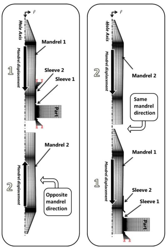
This section studies the influence of successive expansions of a hole. To simulate this process, modeling considered the crossing of several mandrels in the same hole before the final reaming of the hole was performed (Fig. 2). At each step of expansion, a new sleeve was inserted into the hole. Two successive expansion scenarios are thus considered. First of all, the expansion obtained in two opposite directions (OD) is simulated. The idea here is that the opposite direction may restore an effective radial expansion rate at the mandrel entrance (of the first expansion). This scenario is then compared with a double expansion carried out in the same direction (SD), which is easier to achieve industrially. The purpose is to study the
impact of these scenarios on the residual state of the hole, analyzing, for example, the distribution and intensity of tangential compressive fields and residual strain. A first model simulates two successive expansions according to the z and -z directions (Fig. 2, left) while a second simulates two successive expansions in the z direction (Fig. 2, right). Note that, in both scenarios, the boundary conditions are representative of actual experimental conditions. The expanded part is kept axially free so that it can move and creep along the sleeve. We thus hope to capture all effects associated with the direction of travel during tooling displacement.
3. Numerical results - circumferential stress analysis
3.1 Single split sleeve cold expansion
This section reports the results obtained through FE modeling of the split sleeve process performed once within a titanium hole. Results are taken from a simulation considering a 6% initial expansion ratio. Because of its predominance in the onset and propagation of cracks in the hole section, only the circumferential stress will be analyzed in this paper. The simulations show the compressive stress close to the hole section. The results shown (Fig. 3 (a)) compares the circumferential residual fields generated after cold expansion and (Fig. 3 (b)) shows these fields after cold expansion followed by reaming to the functional diameter. Stresses are plotted over three paths corresponding to the entrance face of the mandrel, the midsection of the specimen and the exit face of the mandrel. For the entrance and exit sections, paths were chosen at the first row of elements under the free surface to avoid some singularities existing near the hole surface.
A good way to analyze the effectiveness of the expansion is to observe the intensity of the compressive peak and the extent of the compressive area. We find the well-known phenomenon of reduced compressive stresses at the entrance side of the mandrel, “the weak point” (Fig. 3 (a)). We note also that the compressive fields are more extensive in the mandrel entrance and exit sections than in the midsection (compressive boundary is 4.2 mm instead of
3 mm). (Fig. 3 (b)) shows the strong benefit of reaming and relaxation on the homogeneity of the stresses in the thickness (arrow 2). We note that the reaming induced homogenization of the stress along the section. Stress peak intensities were closer at the edge of the hole, especially at the mandrel entrance position, where the stress became more compressive (about –150 MPa).
In order to improve the efficiency of the process and, more precisely, the intensity of stresses at the mandrel entrance, we now check the influence of performing the double expansion in different directions. The results will then be compared with those obtained after a double expansion performed in the same direction.
3.2 Successive Double Cold Expansion Performed in Opposite Directions (OD)
The results presented in this section were obtained from simulations of successive double expansion carried out in two different directions (z and -z). The expansion ratios were fixed at 6% relative to the initial hole (the same tooling dimension is used). (Fig. 4) shows the distribution of circumferential residual fields at different steps of the process. For convenience, we will always call the same side the "exit" face: it corresponds to the exit face of the mandrel at the first expansion step. Similarly, the entrance face of the first step will still be called the entrance face in the following steps.
We thus find that, following the first expansion, the compressive stresses are reduced at the mandrel entrance, as shown in section 3.1. Thereafter, the second expansion in the opposite direction induces a very interesting balance of the stress fields. This weakness is now seen to affect the mandrel entrance of the second mandrel. This result is remarkable and can be connected with the out of plane displacement (axial direction) of the material surrounding the hole and kinematic hardening effects, inducing a lowering of the compressive yield strength. We note that, after reaming and relaxation, the homogeneity of the stresses is very good and residual circumferential fields are almost symmetrical with respect to the midsection of the hole.
The previous observations were confirmed by the analysis of the stress curves plotted at the entrance, exit and midsection of the part. (Fig. 4 (a, b)) shows how the compressive peak switches between the two outer surfaces of the part after successive expansions (arrows n°1 and n°2). (Fig. 4 (c)) shows that, after reaming, this scenario gives a homogeneous expansion of the hole and no significant differences are observed in curve shapes between the entrance and the exit of the mandrel (only a slight weakness persists at the entrance of the second mandrel). In addition, no change is observed in the value and distribution of the tensile stress generated away from the hole. These results show the effectiveness of this expansion scenario on the process efficiency. In cases where no damage is found in the titanium alloy microstructure after a multiple expansion, it seems that performing a double expansion could contribute to higher fatigue performance and/or the elimination of weak points that allow fatigue cracks to grow.
3.3 Successive Double Cold Expansion Performed in the Same Direction (SD)
We now present the results obtained from simulations of successive expansions carried out in the same direction. Again, initial expansion ratios were fixed at 6% and kinematic hardening was used. (Fig. 5) shows the distribution of circumferential residual fields at different steps of the process. It is observed that expansion efficiency is improved at the mandrel entrance whereas, at the exit side, the stress intensity and distribution appears less important. We note that, after reaming and relaxation, homogeneity of the stresses is improved throughout the thickness.
Analysis of the stress curves confirmed this tendency. More precisely, (Fig. 5 (a, b)) shows that the second expansion involves only a slight increase in stress intensity at the mandrel entrance whereas it involves a marked reduction of the stress intensity at the mandrel exit, of about 200 MPa (arrows n°1 and n°2). On the other hand, (Fig. 5 (c)) shows that reaming and relaxation allowed intensities and shapes of compressive areas to be reached that were close to those observed after a single expansion (Fig.3 (b)). Note that the successive double
expansion led to a slight increase in the size of the compressive area as well as the stress intensities. It can be deduced that this scenario of successive expansion (SD) is less efficient than the previous one (OD) according to the homogeneity of the compressive fields generated in the hole section.
4. Assessment of stress at the edge of a cold expanded hole
4.1 Principle of the measurement method
This section presents the evaluation of an experimental technique adapted for stress measurement at the edge of cold expanded holes. The incremental hole drilling technique consists in measuring the deformations recorded by a gauge after drilling of a volume of material containing residual stresses. The internal stress removed from within the part causes a new mechanical equilibrium around the drilled hole, which results in deformations measured in the gauges located at its periphery. The drilling can be done particularly in the center of a rosette specially designed for these applications and the procedure is standardized.
[31] According to the magnitude and direction of the deformation recorded during drilling, the
geometric parameters of the experiment and the mechanical properties of the materials used (Young's modulus and Poisson's ratio), it is possible to reconstruct the stress field that existed before the drilling of the hole. This method provides a value of “first order” residual stresses, i.e. the macroscopic stresses.
In previous sections, the numerical study of the expansion process resulted in a good theoretical understanding of the circumferential stress fields generated by the split sleeve process. We have seen that the stress fields generated by expansion are first known to be biaxial (radial and circumferential) in the plane of the plate (i.e. orthogonal to the axis of the expanded hole). To measure this stress field, it appears sufficient to use the hole drilling method (HDM) that enables the reconstruction of a biaxial stress field that is homogeneous in the hole thickness. This method is based on the measurement of the biaxial strain field relaxed
after the drilling of a small hole in the study area. Lame’s equations then allow a rapid reconstruction of the initial stress field. However, the stresses generated by the split sleeve process are also known to be heterogeneous in the thickness of the treated hole. We have seen that stress fields generated at the mandrel entrance should be less intense than at the mandrel exit. Thus, in order to capture all the tri-axial variation of the stress, the incremental hole drilling technique (IHDM), a more complicated version of the previous one, is used. Here, the variation of deformation is also captured through drilling increments (in depth), by successively removing a well-defined volume of material (coring). The drilling is carried out according to a fixed number of increments where strain values are recorded and where stresses will be deduced. This method requires the use of a finite element model of the experimental process to identify the laws connecting the value read at the surface of the part (where the gauge is stuck) with the change in residual stress at the bottom of the drilled hole. It allows the well-known coefficients of influence to be determined.[32] Correlation
coefficients are specific for each experimental configuration (hole diameter, plate thickness, rosette dimensions, etc.) and for each increment. All the coefficients are computed using a dedicated numerical modeling of the experimental configuration. When a drilling increment is completed, the drilling tool is released from the hole. The deformations are then recorded over a fixed time. The software deduces the mean and standard deviation values stored in order to interpret them later to calculate the nominal stress value and an uncertainty associated with the stabilization of the deformation. The main assumptions of the method are the use of the mechanics of linear elastic continuum: constant shear between the layers of increments, absence of shear between the layers of material removed and non-consideration of out-of-plane stresses.
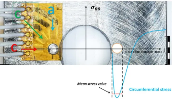
For cold expansion issues, the basic idea is shown (Fig. 6). Thanks to the small diameter of the hole that is drilled for the deformation measurement, we are likely to capture the value of the hoop stress that is then theoretically almost constant at the compressive peak (close to the
compressive yield strength). As seen in section 3.1, the compressive threshold at the hole edge may propagate quite far (≈ 2 mm), at a constant stress intensity in the mandrel entrance, mid and mandrel exit sections. As will be seen in the experimental procedure, the diameter of the measurement hole is smaller than the width of this threshold and allows it to be measured. Beyond these 2 mm, the compressive stress decreases greatly and its variation will be difficult to capture precisely. The objective is to drill a small hole that is almost tangent to the perimeter of the cold expanded hole. The measurement hole is then surrounded by the deformation gauges, which can record the variation in deformation generated during the drilling of the hole. Thus, if the orientation of the measurement gauges is mastered, the method seems quite suitable to determine the maximum value of the circumferential compressive threshold, which is theoretically very constant and extensive at the exit face of the mandrel. On the other hand, the radial stress value is theoretically not constant close to the hole edge, so an averaged value will be measured. The software used is calibrated to calculate the plane stress state (S11, S22 and S12) in the direction 1,2 of the strain gauges (3).
̿ , ) = . ..
. . . (3)
Thus the calculated stresses are not the principal stress but the stresses in the “gauge” coordinate system and the associated shear in the measuring direction. As shown in (Fig. 6), the direction 11 is collinear with the gauge a (0°) and direction 22 is collinear with the gauge c (90°). The center of the coordinate system is the center of the drilling target. The rosette was bonded with the 0° direction tangential to the hole edge in the area of the net-section to allow comparison with our numerical results. The 90° gauge was thus oriented to measure radial strain. With this approach, direct conversion is possible between the polar coordinate system , and the gauge coordinate system 1, 2 . For now, we make a first assessment of the feasibility of the measurement method and a preliminary analysis of the results for the study of the expanded hole. In fact, despite all the theoretical advantages of this method, some
limitations are still present on the quantitative confirmation of the results obtained. In particular, it is necessary to check the possible existence of a correction that has to be performed on the coefficients of influence in the case of a free edge close to the measuring hole as the loss of stiffness caused by the decrease in the volume of material surrounding the hole may influence coefficients, mainly in the radial direction. To limit this potential effect on the value of the circumferential stress, the 0° gauges (direction 1) are oriented in the direction of the desired circumferential stress. Finally, attention must be paid to the possible reserve hardening of the measurement hole, which exhibits a high stress concentration.
4.2 Experimental procedure
In order to perform the drilling and data acquisition, a MELIAD RMSHD40 device was used to control the drilling increments and also to calculate the influence coefficients and perform post-processing of the recorded deformation data. To measure strain, rosettes with three strain directions (0°, 90° and 45°) were used to define the plane stress state. These gauges have a target, 1.8 mm in diameter, in their center to achieve drilling. The largest drilling diameter was used as it provided higher precision on the strain value recorder (diameter of 1.8 mm). Smaller drilling diameters (1 mm) are available for better resolution to capture gradients on the shape of the residual stress fields.
In the present study, we chose HBM K-Ry6 rosettes, which are very small and pre-wired, in order to simplify the instrumentation of the cold worked specimens. The temperature compensation factor was not considered because the gauges used exhibited negligible variations in their characteristics over the range 15-30°C, which included the experimental conditions. The challenge was to achieve the bonding of gauges near the hole, always in the same position, as selected (Fig. 6). Apart from a thorough cleaning, no surface preparation was performed before bonding the gauge. Furthermore, in order to avoid erroneous results, measurements at the entrance and exit face were never made face to face. This avoided the risk of relaxation in the same ligament of the specimens. Once the gauge was bonded, the
instrumented specimen was placed on the table of the controlled drilling device. The specimen was then connected to the acquisition system and the gauge was balanced. The whole was connected to a computer workstation with dedicated software, which, in particular, controlled the drilling device.
The drilling was initiated in carefully chosen cutting conditions in order to generate the desired flat-bottomed and square-cornered hole shape. To not add further residual stresses during cutting and thus affect the results, a new “flat bottom” carbide end mill was used for each measurement point. The tool and machining parameters selected for the incremental drilling operation are discussed Table 1. To reduce cutting forces, the feed rate was very low. Given the very small diameter, the spindle speed was very high in order to maintain a sufficient cutting speed. The biggest technical difficulty was the precise centering of the measuring hole with respect to the target of the rosette. This was done manually on a micrometric table, using magnifiers. The worst experimental defect that occurred was a 0.1 mm discrepancy in coaxiality between the target and the hole. The hole was then divided into a fixed number of depth increments, where the stress was calculated. We defined 19 increments for a drilling depth of 1.05mm.
4.3 IHDM analysis - Stress fields after single and OD cold expansion
We now present the results obtained using this experimental technique. We were able to treat various cold working configurations that were simulated in the numerical section. The measurements were generally performed twice for each configuration in order to check the consistency and repeatability of the results. We first observed the results obtained on a Ti-6Al-4V sheet immediately after machining and tempering in order to find the initial stress state. The gauge was then bonded and oriented with respect to the rolling direction of the sheet. Values of residual stress close to 0 MPa were measured in all directions on the plate (rolling direction and transverse direction) (Fig. 7). However, the two increments located below 50 µm in depth showed very significant compressive peak: less than -600 MPa on
machined and tempered plates. These stresses were also balanced by a less intense but more extensive (200 µm) tensile field. An additional measurement was made at the edge of a “virgin” hole. This measurement also showed negligible stresses as soon as we penetrated slightly below the surface.
Next, we measured the stress in titanium specimens that were cold expanded according to the split sleeve process, with an initial expansion ratio of 6%. These specimens were identical to those considered section 3.4 and corresponded exactly to the conditions simulated in the numerical study. The measurement at the edge of an expanded hole proved very interesting (Fig. 7). At the mandrel exit, we observed a circumferential field that was very intense and relatively constant through the thickness, ranging between -800 and -1100 MPa. At the mandrel entrance, we observed a residual stress close to 0 MPa at the surface, which quickly
became highly compressive in depth, where it reached a value close to -1100 MPa. As the numerical study had indicated that a good way to optimize the expansion process of a
titanium alloy was to carry out a second expansion in the direction opposite to that of the first (OD process), the measurement methodology described above was used to verify the impact of this theoretical "optimization" experimentally. (Fig. 7) shows also the results obtained at the mandrel exit and entrance faces after the two successive expansions. Several points are worth noting. First, a clear increase can be seen in the intensity of the compressive area at the entrance face of the mandrel. Thus the circumferential stress quickly reached -1000 MPa (z = 0.1 mm) while, with a single expansion, these compression levels occurred at greater depth, close to 1 mm. Moreover, the stresses were always highly compressive as depth in the section increased (>1100 MPa). These measurements prove that the OD successive expansion can have a very positive impact on the homogeneity of the stresses in the expanded sections and is likely to solve the problem of the weak point localized at the entry face of the mandrel. On the other hand, a very interesting phenomenon of lowering of the stress level is visible at the output face of the mandrel, the stress intensity being within the range [-750; -500] MPa. This
result, already forecasted by the numerical simulations, can be specifically explained by the significant Bauschinger effect of this alloy. These results indicate that, despite the improvement in the homogeneity of the stresses within the section, there is a risk of compensation of the benefit related to the overall reduction in stress level after kinematic hardening. Only fatigue tests would reveal which parameter has the most influence on fatigue performance.
4.4 IHDM analysis after reaming - Stress fields after single and OD cold expansion
For the standard industrial process of cold expansion, reaming is generally carried out after cold working in order to remove the expansion defects and allow correct installation of fasteners. In the present case, we wanted to check the impact of this reaming on the distribution and intensity of residual stress fields. Additional specimens were therefore expanded using the split sleeve process (6% cold expansion) and reamed on machining centers. The reaming process was orbital (biaxial kinematics of the cutting tool), using a flat-nose end mill. The tool and machining parameters selected for the reaming operation are discussed Table 1. This process reduced heating and cutting forces and was therefore more "neutral" regarding the residual stresses at the hole edge. The holes were reamed to a diameter 9.52 mm and chamfered. Localization of the measure point for IHDM is slightly modified. The incremental hole measurements revealed a notable impact of the reaming process on the stress field in the hole edge (Fig. 8). Thus, it can be seen that, at the exit face of the mandrel, the overall intensity of the circumferential stress was reduced, meaning that a stress redistribution had taken place in the section or relaxation had occurred during the reaming operation. While the stress remained relatively constant over the measured depth, the measured values were within the [-750; -500] MPa range. On the other hand, the results observed at the face where the mandrel entered were very interesting and it could be seen that the weak point observed post expansion was removed by the reaming operation. A much more homogeneous stress was thus found in the depth, the stress intensity being within the range
[-750; -500] MPa. These results were highlighted by the numerical study, which explained the phenomenon by a simple redistribution of stress after reaming. These measurements suggest that the reaming process can be very beneficial for the distribution of stresses and thus the fatigue performance of the hole. Reaming was also performed on specimens that were expanded twice (OD). Again, the compressive circumferential fields were well balanced on the exit face, where the stress level stabilized at -1000 MPa (Fig. 8). This balance was accompanied by a slight reduction in circumferential stress at the entrance face, then the stress came within the range [-1000; -750] MPa. The impact of reaming on the “final” circumferential stress fields at the hole edge can thus be observed. However, the solution of double successive expansion still appears to be beneficial for optimizing the process and extra compression at the hole edge can be generally observed. In fact, it can be concluded from this study that the expansion process in titanium alloys cannot be dissociated from the reaming process, which necessarily takes place immediately after the expansion. Representation of stress measurements in the thickness of the expanded sections helps to realize the impact of the double expansion (Fig. 9). The measurement intervals are here connected using extrapolation assuming linear evolution of the stress within the section z ∈ [1mm; 4mm].
5. Conclusion
This paper discusses the consequences of the successive split sleeve cold expansion of a single hole in titanium through a numerical study. In order to resolve the issue, dedicated finite element modeling of the cold expansion process was developed to simulate cases where the expansion was carried out twice in the same direction and in two opposite directions. The residual fields generated were analyzed and the results compared with experimental feasibility results and stress measurements using an incremental hole drilling technique. From the results obtained, several conclusions can be drawn:
1) Single split sleeve cold expansion process induced compressive circumferential stress fields at the edge of a titanium hole. These fields were significantly heterogeneous
through the thickness of the hole treated. Heterogeneity concerned the extent and intensity of the fields. “Weak points” were mainly in the area of the mandrel entrance.
2) A first model allowed two successive expansions to be simulated according to the z and -z direction (opposite directions). It was observed that, after reaming, the homogeneity of the compressive fields was improved and that weak points were no longer observed over the hole section.
3) A second model simulated two successive expansions in the z direction (same sense). The homogeneity of the compressive fields after reaming was slightly improved. However, weak points remained at the mandrel entrance where the extent and intensities of the fields were still lower than in other sections.
4) A new experimental assessment of the residual stress at the edge of the cold expanded hole has been proposed. The technique allows the circumferential stress to be measured at the mandrel entrance and exit faces. The results show that heterogeneity exists in “real” cold expanded holes and that successive expansion in opposite directions improves the efficiency of expansion. Moreover, the existence of the Bauschinger effect was highlighted experimentally and the influence of the reaming on the redistribution of the stresses in cold expanded sections was assessed.
After finding that it was possible to improve the process efficiency on these alloys, a multiple expansion methodology was proposed, which improved the homogeneity of the stress field in the hole edge. The numerical study presented in this paper validates the effectiveness of this strategy and tends to confirm that the fatigue performance of holes could be improved. The next step will be to validate these conclusions by experimental fatigue tests on elementary fatigue specimens, and also to check its effectiveness on assembled (i.e. bolted) specimens.
In order to judge the quality of the model, the previous results were compared with experimental measurements. First of all, the values obtained from the measured residual expansion ratios (before reaming) were compared as these very specific results showed very little spread. Residual expansion rate was obtained by measuring the cold worked hole (residual hole) using an internal micrometer (out of the affected zone). The residual expansion rate (RE) was calculated for each specimen and defined by relation (2).
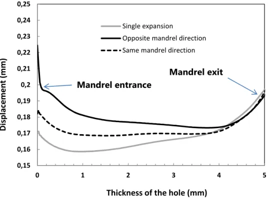
= ∅$ % &'∅ ∅ (2) Experimentally, these residual diameters were measured at the midsection of the coupons. Coupons were made of annealed Ti-6Al-4V. Maximum tolerance on the hole diameter was ± 0.02 mm, which ensured good accuracy of the expansion ratios actually applied. Expansion was performed using split sleeve cold expansion tooling on “5 hole” feasibility specimens, always in the plane of the sheets (longitudinal-longitudinal/transverse orientation). These normalized specimens had a width equal to three times the nominal hole diameter (free-edge distance) and the distance between two holes was equal to five nominal diameters so as to avoid reciprocal influence. These values can be compared with the numerical radial coordinates measured on the hole section before reaming. (Fig. 10) shows the numerical residual profile after a single expansion and after successive expansions. It can be seen that successive expansions tend to increase the radial displacement and thus the residual ratio. Moreover, the classical "inverted barrel" shape of the hole observed after a single expansion is modified. The final profile is also dependent on the direction of expansion. From these profiles, we can extract the values measured at the midsection of the hole (axial coordinate z=2.5mm), deduce the residual diameters and thus compare them with experimental results. A comparison of the numerical and experimental expansion ratios is shown in (Fig. 11 (a)). Comparison was made for a single 6% expansion and for two successive 6% expansions in
opposite directions (OD). Moreover, we decided to compare the results obtained using kinematic hardening and isotropic hardening.
The results (Fig. 11 (b)) show that, for a single and for a double successive expansion (OD), the value of the compressive peak is highly dependent on the law chosen for the material. Thus, if the law used is sensitive to the decrease in yield strength after bidirectional hardening, a decrease of the intensity of the compressive peak can be seen. However, there is no change in the general trends relating to the residual fields generated and, in particular, there is no change in the compressive boundaries in the entrance, exit and median sections. As long as a means can be found to measure the value of the compressive peak precisely, it is possible to refine these elasto-plastic laws to obtain a reliable model for predicting the stress distribution in the expanded section of hard alloys. Concerning the residual ratio measured, whatever the material laws chosen, there is an excellent correlation of these variables. In fact, the model was able to predict the residual expansion with great accuracy. Thus, by using the isotropic and kinematic hardening laws, the residual expansion could be predicted with an accuracy within the experimental dispersion. Moreover, the values obtained were extremely close to the average values of the experimental tests (<1%).
Received: ((will be filled in by the editorial staff)) Revised: ((will be filled in by the editorial staff)) Published online: ((will be filled in by the editorial staff)) _[1] R.E. Peterson, in Stress concentration design factors, Wiley, New York 1953.
_[2] M. Paredes, R. Canivenc, M. Sartor, Proc. of the Institution of Mech.Eng. Part G: J. of Aero. Eng. 2013.
_[3] L. Phillips Joseph, AFML-TR-74-10 1974.
_[4] D.L. Rich, L.F. Impellizzeri, ASTM STP 637 1977.
_[5] W.Z. Yan, X.S. Wang, H.S. Gao, Z.F. Yue, Eng. Fract. Mech. 2012, 88. _[6] A.C. Rufin, J. Eng. Gas Turbines Power 1993, 115.
_[7] G.T. Sha, B.A. Cowles, R.L. Fowler, in Emerging technologies in aerospace structures, design structural dynamics and materials, ASME, New York 1980. _[8] L.F. Reid, European Conference for Aerospace Sciences (EUCASS).
_[9] M.E. Karabin, F. Barlat, R.W. Schultz, Journal of Mat. Pro. Tech. 2007, 189. _[10] X. Zhang, Z. Wang, Int. J. of Fatigue 2003, 25.
_[11] A. T. Ozdemir, R. Hermann, J. of mat. and sci. 1999, 34. _[12] T.N. Charkherlou, J. Vogwell, J. of Eng. Fail. Anal. 2003, 10. _[13] V. Nigrelli, S. Pasta, J. of Mat. Pro. Tech. 2005.
_[14] J. Liu, H. Wu, J. Yang, Z. Yue, Eng. Frac. Mech. 2013.
_[15] M. Elajrami, H. Melouki, F. Boukhoulda, Int. J. of Min., Met. & Mech. Eng. 2013, 1. _[16] M. Su, A. Amrouche, G. Mesmacque, N. Benseddiq, Comp. Mat. Sci. 2008, 41. _[17] J.S. Jang,D.W. Kim, Proc. IMechE. Part B: J. Engineering Manufacture 2008, 222. _[18] M. Bernard, T. Bui-Quoc, M. Burlat, Fat. and Frac. Eng. Mat. and struc. 1995, 18. _[19] M. Lapalme, M. Hoseini, P. Bocher, A. Colle, M. Lévesque, Exp. Mech. 2014, 54. _[20] X. Chen, L. Yang, X. Chen, C. Chirac, C. Du, D. Zhou, SAE International 2011. _[21] G. L. Cloud, Exp. Mech., 1980, 20.
_[22] J. F. Doyle and J. W. Phillips, in Manual on Experimental Stress Analysis, Society for Experimental Mechanics Fifth Edition, 1989.
_[23] P. Beaver, J. Mann, J. Sparrow, in EIS 1 Measurement and Fatigue, Vol. 1, J.M.Tunna, UK 1986.
_[24] S. Ismonov, S. Daniewicz, J. Newman Jr, M. U. M. Hill, J. of Eng. Mat. and Tech.
2009, 131
_[25] J. G. Zhao, A. M. Huntz, Revue Phy. Appl. 1987, 122. _[26] A. Niku-Lari, Cetim, France.
_[27] A. Özdemir, L. Edwards, Fat. & Frac. of Eng. Mat. & Struc. 2008, 20. _[28] M. B. Prime, Eng. Applications of Res. Stress 2011, 8.
_[29] R. Kelsey, Proc. SESA XIV 1956, 1.
_[30] H. Kitano, S. Okano, M. Mochizuki, J. of Phy.: Conference series 2012, 1379. _[31] American society for testing and materials, ASTM standard E 837 1992. _[32] A. Niku-Lari, J. Lu, J.F.Flavenot, J.of Mech. Working Tech. 1985, 11.
Fig. 1. Axisymmetric modeling of split sleeve expansion process and location of the critical section modeled (taken from a fatigue specimen).
Fig. 2. Modeling multiple successive cold expansions through axisymmetric FEM. Two expansions in opposite mandrel directions (OD) (left), and two expansions in the same
Fig. 3. Overview of residual circumferential stress fields and associated curves after Expansion (6%) of the hole (a), followed by reaming (b).
Fig. 4. Scenario OD: overview of residual circumferential stress fields and associated curves after first Expansion (6%) of the hole (a), second expansion (b), followed by reaming (c).
Fig. 5. Scenario SD: overview of residual circumferential stress fields and associated curves after first Expansion (6%) of the hole (a), second expansion (b), followed by reaming (c).
Fig. 6. Location of the gauge at the exit face of a cold expanded Ti-6Al-4V hole
Operation
Incremental drilling (stress measurement)
Reaming of the cold expanded hole
Tool specification 2 flutes carbide end mill cutter 3 flutes carbide (+TiAlN coating) end mill cutter
Diameter (mm) 1.8 8
Feed rate – (mm/rev) 1.5x10^-6 0.06
VC (m/min) 250 20
Lubrication Dry Abundant
Tool displacement Axial Orbital
Table. 1. Tools and machining parameters selected for the incremental drilling and reaming operations.
Fig. 7. Stress field measured by IHDM: milled and stress relieved, 6% and 2 × 6% in opposite directions, 9.52 mm αβ Ti-6Al-4V hole.
-1500 -1300 -1100 -900 -700 -500 -300 -100 100 0 0,2 0,4 0,6 0,8 1
σ
θ θ (M P a ) Depth (mm) Machining + tempering IHDM - Exit face IHDM - Entrance face IHDM - Exit face - X2 IHDM - Entrance face - X2Fig. 8. Stress field measured by IHDM: milled and stress relieved, 6% and 2 × 6% in opposite directions, 9.52 mm αβ Ti-6Al-4V hole after orbital reaming.
-1400 -1200 -1000 -800 -600 -400 -200 0 200 0 0,2 0,4 0,6 0,8 1
σ
θ θ (M P a ) Depth (mm) Machining + tempering IHDM - Exit face - Reaming IHDM - Entrance face - Reaming IHDM - Exit face - X2 - Reaming IHDM - Entrance face - X2 - ReamingFig. 9. Stress analysis at the hole edges after cold expansion (top) and after cold expansion and reaming (bottom). Entrance (z=0) and exit face (z=5) measurement connected using
linear extrapolation.
Fig. 10. Radial deformation of the hole along its thickness after cold expansion.
Fig. 11. Analysis of the residual expansion ratio: correlation between experimental and numerical results for single 6% expansion and double successive 6% expansion (a). Scenario
OD: Circumferential residual fields according to two hardening laws (b)
0,15 0,16 0,17 0,18 0,19 0,2 0,21 0,22 0,23 0,24 0,25 0 1 2 3 4 5 Di sp la ce m e n t (m m )
Thickness of the hole (mm)
Single expansion
Opposite mandrel direction Same mandrel direction
Mandrel exit Mandrel entrance
Alain Daidie, Manuel Paredes, Clément Chirol, Victor Achard* Optimization of the Cold Expansion Process for Titanium Holes